US5850141A - Annular speed sensor with a tone ring having both axial and radial magnetic fields - Google Patents
Annular speed sensor with a tone ring having both axial and radial magnetic fields Download PDFInfo
- Publication number
- US5850141A US5850141A US08/876,053 US87605397A US5850141A US 5850141 A US5850141 A US 5850141A US 87605397 A US87605397 A US 87605397A US 5850141 A US5850141 A US 5850141A
- Authority
- US
- United States
- Prior art keywords
- axial
- radial
- teeth
- field receiving
- tone ring
- Prior art date
- Legal status (The legal status is an assumption and is not a legal conclusion. Google has not performed a legal analysis and makes no representation as to the accuracy of the status listed.)
- Expired - Fee Related
Links
- 230000005291 magnetic effect Effects 0.000 title claims abstract description 62
- 238000004804 winding Methods 0.000 claims description 7
- 238000005096 rolling process Methods 0.000 claims description 6
- 230000004907 flux Effects 0.000 claims description 4
- 230000005294 ferromagnetic effect Effects 0.000 claims description 3
- 239000000463 material Substances 0.000 claims description 2
- 238000007789 sealing Methods 0.000 claims 5
- 239000003302 ferromagnetic material Substances 0.000 claims 2
- 230000001939 inductive effect Effects 0.000 claims 2
- 238000010276 construction Methods 0.000 abstract description 5
- 230000000694 effects Effects 0.000 abstract description 5
- 230000007613 environmental effect Effects 0.000 abstract 1
- 238000004806 packaging method and process Methods 0.000 description 4
- 238000001514 detection method Methods 0.000 description 3
- 230000005355 Hall effect Effects 0.000 description 2
- 230000007423 decrease Effects 0.000 description 2
- 230000005426 magnetic field effect Effects 0.000 description 2
- 238000004519 manufacturing process Methods 0.000 description 2
- 230000001133 acceleration Effects 0.000 description 1
- 239000000956 alloy Substances 0.000 description 1
- 229910045601 alloy Inorganic materials 0.000 description 1
- 230000000712 assembly Effects 0.000 description 1
- 238000000429 assembly Methods 0.000 description 1
- 239000000356 contaminant Substances 0.000 description 1
- 239000000428 dust Substances 0.000 description 1
- 238000012986 modification Methods 0.000 description 1
- 230000004048 modification Effects 0.000 description 1
- 230000005405 multipole Effects 0.000 description 1
- 230000000717 retained effect Effects 0.000 description 1
- 150000003839 salts Chemical class 0.000 description 1
- 230000035945 sensitivity Effects 0.000 description 1
- XLYOFNOQVPJJNP-UHFFFAOYSA-N water Substances O XLYOFNOQVPJJNP-UHFFFAOYSA-N 0.000 description 1
Images


Classifications
-
- F—MECHANICAL ENGINEERING; LIGHTING; HEATING; WEAPONS; BLASTING
- F16—ENGINEERING ELEMENTS AND UNITS; GENERAL MEASURES FOR PRODUCING AND MAINTAINING EFFECTIVE FUNCTIONING OF MACHINES OR INSTALLATIONS; THERMAL INSULATION IN GENERAL
- F16C—SHAFTS; FLEXIBLE SHAFTS; ELEMENTS OR CRANKSHAFT MECHANISMS; ROTARY BODIES OTHER THAN GEARING ELEMENTS; BEARINGS
- F16C41/00—Other accessories, e.g. devices integrated in the bearing not relating to the bearing function as such
- F16C41/007—Encoders, e.g. parts with a plurality of alternating magnetic poles
-
- F—MECHANICAL ENGINEERING; LIGHTING; HEATING; WEAPONS; BLASTING
- F16—ENGINEERING ELEMENTS AND UNITS; GENERAL MEASURES FOR PRODUCING AND MAINTAINING EFFECTIVE FUNCTIONING OF MACHINES OR INSTALLATIONS; THERMAL INSULATION IN GENERAL
- F16C—SHAFTS; FLEXIBLE SHAFTS; ELEMENTS OR CRANKSHAFT MECHANISMS; ROTARY BODIES OTHER THAN GEARING ELEMENTS; BEARINGS
- F16C33/00—Parts of bearings; Special methods for making bearings or parts thereof
- F16C33/72—Sealings
- F16C33/723—Shaft end sealing means, e.g. cup-shaped caps or covers
-
- F—MECHANICAL ENGINEERING; LIGHTING; HEATING; WEAPONS; BLASTING
- F16—ENGINEERING ELEMENTS AND UNITS; GENERAL MEASURES FOR PRODUCING AND MAINTAINING EFFECTIVE FUNCTIONING OF MACHINES OR INSTALLATIONS; THERMAL INSULATION IN GENERAL
- F16C—SHAFTS; FLEXIBLE SHAFTS; ELEMENTS OR CRANKSHAFT MECHANISMS; ROTARY BODIES OTHER THAN GEARING ELEMENTS; BEARINGS
- F16C33/00—Parts of bearings; Special methods for making bearings or parts thereof
- F16C33/72—Sealings
- F16C33/76—Sealings of ball or roller bearings
- F16C33/78—Sealings of ball or roller bearings with a diaphragm, disc, or ring, with or without resilient members
- F16C33/7886—Sealings of ball or roller bearings with a diaphragm, disc, or ring, with or without resilient members mounted outside the gap between the inner and outer races, e.g. sealing rings mounted to an end face or outer surface of a race
-
- G—PHYSICS
- G01—MEASURING; TESTING
- G01P—MEASURING LINEAR OR ANGULAR SPEED, ACCELERATION, DECELERATION, OR SHOCK; INDICATING PRESENCE, ABSENCE, OR DIRECTION, OF MOVEMENT
- G01P3/00—Measuring linear or angular speed; Measuring differences of linear or angular speeds
- G01P3/42—Devices characterised by the use of electric or magnetic means
- G01P3/44—Devices characterised by the use of electric or magnetic means for measuring angular speed
- G01P3/443—Devices characterised by the use of electric or magnetic means for measuring angular speed mounted in bearings
-
- G—PHYSICS
- G01—MEASURING; TESTING
- G01P—MEASURING LINEAR OR ANGULAR SPEED, ACCELERATION, DECELERATION, OR SHOCK; INDICATING PRESENCE, ABSENCE, OR DIRECTION, OF MOVEMENT
- G01P3/00—Measuring linear or angular speed; Measuring differences of linear or angular speeds
- G01P3/42—Devices characterised by the use of electric or magnetic means
- G01P3/44—Devices characterised by the use of electric or magnetic means for measuring angular speed
- G01P3/48—Devices characterised by the use of electric or magnetic means for measuring angular speed by measuring frequency of generated current or voltage
- G01P3/481—Devices characterised by the use of electric or magnetic means for measuring angular speed by measuring frequency of generated current or voltage of pulse signals
- G01P3/487—Devices characterised by the use of electric or magnetic means for measuring angular speed by measuring frequency of generated current or voltage of pulse signals delivered by rotating magnets
-
- F—MECHANICAL ENGINEERING; LIGHTING; HEATING; WEAPONS; BLASTING
- F16—ENGINEERING ELEMENTS AND UNITS; GENERAL MEASURES FOR PRODUCING AND MAINTAINING EFFECTIVE FUNCTIONING OF MACHINES OR INSTALLATIONS; THERMAL INSULATION IN GENERAL
- F16C—SHAFTS; FLEXIBLE SHAFTS; ELEMENTS OR CRANKSHAFT MECHANISMS; ROTARY BODIES OTHER THAN GEARING ELEMENTS; BEARINGS
- F16C19/00—Bearings with rolling contact, for exclusively rotary movement
- F16C19/02—Bearings with rolling contact, for exclusively rotary movement with bearing balls essentially of the same size in one or more circular rows
- F16C19/14—Bearings with rolling contact, for exclusively rotary movement with bearing balls essentially of the same size in one or more circular rows for both radial and axial load
- F16C19/18—Bearings with rolling contact, for exclusively rotary movement with bearing balls essentially of the same size in one or more circular rows for both radial and axial load with two or more rows of balls
- F16C19/181—Bearings with rolling contact, for exclusively rotary movement with bearing balls essentially of the same size in one or more circular rows for both radial and axial load with two or more rows of balls with angular contact
- F16C19/183—Bearings with rolling contact, for exclusively rotary movement with bearing balls essentially of the same size in one or more circular rows for both radial and axial load with two or more rows of balls with angular contact with two rows at opposite angles
- F16C19/184—Bearings with rolling contact, for exclusively rotary movement with bearing balls essentially of the same size in one or more circular rows for both radial and axial load with two or more rows of balls with angular contact with two rows at opposite angles in O-arrangement
- F16C19/186—Bearings with rolling contact, for exclusively rotary movement with bearing balls essentially of the same size in one or more circular rows for both radial and axial load with two or more rows of balls with angular contact with two rows at opposite angles in O-arrangement with three raceways provided integrally on parts other than race rings, e.g. third generation hubs
-
- F—MECHANICAL ENGINEERING; LIGHTING; HEATING; WEAPONS; BLASTING
- F16—ENGINEERING ELEMENTS AND UNITS; GENERAL MEASURES FOR PRODUCING AND MAINTAINING EFFECTIVE FUNCTIONING OF MACHINES OR INSTALLATIONS; THERMAL INSULATION IN GENERAL
- F16C—SHAFTS; FLEXIBLE SHAFTS; ELEMENTS OR CRANKSHAFT MECHANISMS; ROTARY BODIES OTHER THAN GEARING ELEMENTS; BEARINGS
- F16C2326/00—Articles relating to transporting
- F16C2326/01—Parts of vehicles in general
- F16C2326/02—Wheel hubs or castors
Definitions
- the present invention relates to rotational speed sensors. More particularly, the present invention relates to rotational speed sensors enclosed in a vehicle bearing assembly and adapted for use on a motor vehicle for detecting the rotational speed of a ground engaging wheel.
- ABS anti-lock braking systems
- Such systems are provided to automatically prevent wheel lock-up during hard braking maneuvers so that vehicle stability and directional control can be maintained.
- a critical feature of an ABS is a wheel speed sensor which provides an output to an ABS controller related to wheel rotation. Many passenger cars have such a sensor for each of their four wheels. Through such inputs, the braking system controller can determine if a wheel lock-up condition has occurred or is being approached and thus control the braking system.
- Wheel speed sensors are also used to provide inputs for traction control systems which reduce wheel spin during acceleration.
- ABS wheel speed sensors Numerous designs of ABS wheel speed sensors are presently known. Such sensors generally consist of a rotating part (rotor) in close proximity to a stationary part (stator)
- the rotating part or “tone ring”
- the stationary part includes a transducer which can detect the passing of the features of the tone ring as the tone ring rotates. The detection is indicated by an electrical signal which is emitted by the transducer.
- the transducer may be a variable reluctance device, Hall effect device, magneto-restrictive device, or of some other construction.
- the transducer is a device which senses magnetic fields or changing magnetic fields.
- Variable reluctance transducers are referred to as “passive” sensors in that they generate a voltage without being energized by an external source.
- Active sensors such as a Hall effect device are energized by an externally applied voltage and provide an output responsive to the magnetic fields passing through them.
- One problem with present day wheel speed sensor designs based on magnetic field effects is their sensitivity to variations in the air gap between the rotor and stator.
- One type of magnetic field effect sensor includes a magnetized tone ring which rotates with the wheel bearing.
- the magnetic poles or ferromagnetic features of present wheel speed sensor tone rings (rotors) are generally configured to be either axial or radial. Therefore, present day stators are generally configured to read the axial magnetic poles from the top or bottom surface of the tone ring.
- the tone ring rotates with the wheel, the gap between the tone ring and stator tends to vary due to vibrations and other factors. As the gap increases, the amount of magnetic field read, and thus the resulting output from the stator, decreases.
- the air gaps generally vary in a random manner at random times. These variations can affect the accuracy of the wheel speed sensor.
- an improved wheel speed sensor configured to reduce the effects of variations in the air gap between the rotor and stator.
- an improved wheel speed sensor which is easier and less expensive to produce.
- an improved wheel speed sensor having additional surface area for improving the press-fit strength of the sensor/bearing interface or the sensor/seal interface.
- an improved wheel speed sensor which meets minimum packaging space requirements.
- the present invention provides an annular speed sensor which can be implemented as a motor vehicle wheel speed sensor having an efficient magnetic configuration to provide a high level of electrical output even at relatively low wheel speeds.
- the wheel speed sensor is incorporated into bearing components to provide a compact and efficient hub and bearing assembly.
- the construction of the hub and bearing of this invention provides a sealed environment for the speed sensor.
- One object of the present invention is to provide an improved wheel speed sensor configured to reduce the effects of variations in the axial air gap between the rotor and stator.
- Another object of the present invention is to provide an improved wheel speed sensor which is easier and less expensive to produce.
- the present invention provides an improved wheel speed sensor comprising a multipole tone ring, having axial and radial magnetic poles and a stator having axial and radial field receiving features to read the axial and radial magnetic poles as the tone ring rotates.
- the sensor is configured to minimize the effects of variations in the air gap between the rotor and stator to provide an accurate and reliable wheel speed signal even at relatively low wheel speeds.
- the axial air gap may vary, the radial air gap, between the tone ring and the radial receiving features will likely not vary in the same way or at the same time, thus providing a more accurate and reliable signal.
- the radial air gap does vary, some of the radial receiving features will be closer to the tone ring and some will be farther away. Since all of the receiving features contribute to the signal produced, the net effect of the air gap variation is small.
- the receiving features comprise stator teeth.
- the axial fields are read by teeth positioned adjacent to the axial surface of the tone ring and the radial fields are read by teeth facing the inner radial surface of the tone ring.
- the radial fields and radial receiving features make the sensor less sensitive to the axial air gap between the rotor and stator and therefore make the sensor reading more accurate and reliable.
- the design of the radial field receivers of the present invention provides more surface area along the inner or outer diameter of the stator than the axial field receivers presently used.
- the increased surface area improves the press-fit strength of the sensor/bearing interface or the sensor/seal interface, whichever uses that surface, when the sensor is incorporated into a bearing assembly.
- Another advantage of the present invention is that the sets of teeth can be designed with less stringent requirements for their circumferential alignment, as long as the fields on the tone ring are aligned circumferentially to the teeth. This also decreases the cost of producing the sensor of the present invention.
- FIG. 1 is an exploded pictorial view of a hub and bearing assembly in accordance with this invention
- FIG. 2 is a partial cross-sectional view of the hub and bearing assembly of FIG. 1, shown in an assembled fashion;
- FIG. 3 is a partial pictorial view of an embodiment of the annular sensor having staggered stator teeth and particularly showing the axial and radial receiving features;
- FIG. 4 is an enlarged partial view of the tone ring of the present invention, for use with the annular sensor having staggered stator teeth, schematically showing the axial and radial applied magnetic fields;
- FIG. 5 is a partial view of a tone ring, for use with the annular sensor having staggered stator teeth, showing the magnetic polarity of the radial magnetic areas.
- FIG. 6 is a cross-sectional view of an alternative hub and bearing assembly of the present invention.
- FIG. 7 is an enlarged partial view of the sensor of the present invention as indicated in FIG. 6;
- FIG. 8 is a partial pictorial view of an embodiment of the annular sensor having aligned stator teeth and particularly showing the axial and radial receiving features;
- FIG. 9 is an enlarged partial view of the tone ring of the present invention, for use with the annular sensor having aligned stator teeth, schematically showing the axial and radial applied magnetic fields;
- FIG. 10 is a partial view of a tone ring, for use with the annular sensor having aligned stator teeth, showing the magnetic polarity of the radial magnetic areas.
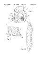
- FIG. 11 is a perspective view of an alternative embodiment of the present invention having the tone ring coaxial with and radially outward of the stator;
- FIG. 12 is a section through the embodiment of FIG. 11 taken along line 12--12;
- FIG. 13 is a perspective view of an alternative embodiment of the present invention having the tone ring coaxial with and radially inward of the stator;
- FIG. 14 is a section through the embodiment of FIG. 13 taken along line 14--14.
- FIGS. 1 and 2 An annular speed sensor implemented in a hub and bearing assembly in accordance with this invention is shown in FIGS. 1 and 2 and is generally designated by reference number 10.
- Hub and bearing assembly 10 as shown in the Figures, is particularly adapted for use on a non-driven axle of a motor vehicle.
- the concepts of the present invention are, however, applicable to hub and bearing assemblies for driven axles and for other non-automotive applications.
- Hub 12 has a radially extending flange which provides a mounting surface for a vehicle wheel (not shown). Hub 12 also defines an inside cylindrical surface 14 and a pair of roller bearing element races including inboard outer race 16 and outboard outer race 18. Hub 12 also has a stepped enlarged bore section 20 which, as will be explained in detail below, provides an area for mounting of a wheel rotation sensor.
- Bearing inner race 22 is positioned inside hub 12, engages a series of ball bearing elements 24 and defines the inboard bearing of the assembly.
- the outboard inner race is not shown in the Figures and would be of conventional construction, defining an inner surface for engagement with an outboard series of ball elements.
- Inner race 22 also has an inside cylindrical passageway 26 which is provided for mounting to a non-rotating spindle 28 of the vehicle. In operation, a vehicle wheel mounted to hub 12 rotates, while inner race 22 is fixed relative to spindle 28.
- a principal feature of hub and bearing assembly 10 in accordance with this invention is the provision of sensor 30 for the detection of wheel rotation. As previously explained, sensor 30 provides an output for control of an ABS or traction control system for a vehicle. Sensor 30 generally comprises a rotor and stator in the form of tone ring 32 and annular transducer 34, respectively. In addition to FIGS. 1 and 2, reference will be made to FIGS. 3, 4, 5, 8, 9, and 10 in a description of sensor 30.
- Tone ring 32 is a permanent magnet in a disk configuration and has a radial face surface 36 and an inner diameter axial face surface 38. Best shown in FIG. 2, tone ring 32 is carried by a tone ring retainer 39 which is press-fit into hub bore 20. In an alternate design, tone ring 32 could be directly fit into hub bore 20.
- FIGS. 4 and 9 show that tone ring 32 defines areas of magnetic polarity arranged along radials with respect to the center of rotation of the hub bearing assembly. The polarity of tone ring 32 alternates along both the radial face surface 36 and the axial face surface 38 in a circumferential direction.
- FIG. 4 schematically shows the applied magnetic fields for tone ring 32 when used with the annular sensor having staggered teeth as shown in FIG. 3 and explained below.
- FIG. 9 schematically shows the applied magnetic fields for tone ring 32 when used with the annular sensor having aligned teeth as shown in FIG. 8 and explained later. While various materials for forming tone rings can be implemented, an alloy of Fe--Cr--Co is used in the present embodiment.
- Annular transducer 34 has a case 44 in the shape of a side-opening shell, having a radial side wall 46 and a pair of cylindrical walls including axial receiving wall 48 and radial receiving wall 50. Walls 48 and 50 are separated to define an annular cavity 52. Both walls 48 and 50 define a plurality of extending teeth 54 and 56, respectively, arranged around their perimeter.
- FIG. 3 shows a configuration which is referred to as having staggered teeth wherein teeth set 54 are radially offset from teeth set 56.
- FIG. 8 which has aligned teeth wherein teeth set 54 and teeth set 56 are radially aligned.
- FIG. 8 does not include bobbin 60 for clarity sake.
- cavity 52 accommodates a coil winding 58 which is wrapped within bobbin 60.
- the number of teeth of each of walls 48 and 50 are equal to the number of regions of tone ring 32 which are magnetized with a particular magnetic polarity.
- transducer teeth 54 and 56 are magnetically coupled to alternating magnetic poles. This induces a reversing magnetic field through transducer case 44.
- arrows along the surface of case 44 and tone ring 32 show the lines of magnetic flux for the illustrated relative orientation between case 44 and tone ring 32.
- the flux field through annular transducer case 44 induces an electromagnetic force (voltage) within coil winding 58.
- Poles 40 and 42 and teeth 54 and 56 respectively, are aligned such that the first set of teeth 54 are magnetically coupled to the axial poles 40, and the second set of teeth 56 are magnetically coupled to the radial poles 42.
- teeth 56 extend past and are separated from the axial face surface 38 of the tone ring 32 by a gap 55.
- the polarity of poles 40 and 42 is configured such that as teeth 54 are magnetically coupled to a magnetic pole of one polarity, teeth 56 are magnetically coupled to a magnetic pole of opposite polarity.
- the polarity of the radial magnetic areas is shown in FIG. 5 for the tone ring 32 which is utilized with a stator having teeth set 54 and teeth set 56 radially offset. As can be appreciated, when the teeth of teeth set 54 are aligned with the north pole of the magnetic areas, the teeth of teeth set 56 are offset and are aligned with the south pole of the next adjacent magnetic area.
- the polarity of the magnetic areas is shown in FIG.
- the tone ring contains both radial fields on the axial surface of the tone ring as well as axial fields on the radial surface, therefore, the teeth 54 and 56 need not be radially staggered with each other.
- the only requirement is that the teeth 54 and 56 be aligned to read opposite magnetic poles.
- the teeth can be either radially aligned or radially staggered. This allows the teeth 54 and 56 to be formed in independent operations thereby making them less expensive to produce.
- Annular transducer 34 is fixed relative to inner race 22, preferably through press-fitting it onto an external cylindrical surface of inner race 22 as shown in FIG. 2.
- the bearing rolling ball elements 24 and sensor 30 are protected by seal 62.
- Seal 62 has a retainer ring 64 which is press-fit onto hub 12 and mounts an elastic lip 66 which contacts transducer case 44. Since transducer 34 is oriented such that the open portion of case 44 is facing ball elements 24, the radial side wall 46 and walls 48 and 50, combine to enclose and protect the bearing elements 24. This configuration also has the advantage that sensor 30 is readily accessible for service or replacement.
- FIGS. 6 and 7 illustrate an alternative hub and bearing assembly 10'.
- a principal feature of hub and bearing assembly 10' in accordance with this invention is a provision of sensor 30' for detection of wheel rotation.
- the hub 12' has a radially extending flange 13' which provides a mounting surface for a vehicle wheel (not shown). The wheel is mounted over and retained by a plurality of lugs 92 which are attached to flange 13'.
- Hub 12' also defines an inside cylindrical surface 14' and a pair of roller bearing element races including inboard race 16' and outboard race 18'.
- Hub 12' also has a stepped enlarged bore section 20' which provides an area for mounting a wheel rotation sensor.
- Bearing inner race 94 is positioned inside hub 12', engages a series of ball bearing elements 24' and defines the inboard bearing of the assembly.
- inner race 94 rotates with the vehicle wheel while outer race 96 remains stationary relative to the inner race 94, race 96 being attached to a spindle (not shown).
- annular stator 98 is secured in a stationary position to outer race 96, while tone ring 100 rotates with inner race 94 thereby rotating with the vehicle wheel.
- FIGS. 11 and 12 illustrate an alternative embodiment wherein a tone ring 110 is coaxial with an annular transducer 112.
- tone ring 110 is a ring like disk spaced about axis 114.
- Annular transducer 112 also spaced about axis 114, is positioned radially inward of tone ring 110 and is positioned such that walls 116 and 118 extend radially outward from an annular wall 120.
- a cavity 122 is formed in annular transducer 112 and accommodates a coil winding 124 which is wrapped within bobbin 126 as previously described in the prior embodiments.
- Tone ring 110 and annular transducer 112 of the present embodiment can be configured to have either staggered or aligned teeth as previously disclosed for the prior embodiments.
- FIGS. 13 and 14 illustrate an alternative embodiment wherein a tone ring 110' is coaxial with an annular transducer 112'.
- tone ring 110' is a ring like disk spaced about axis 114'.
- Annular transducer 112' also spaced about axis 114', is positioned radially outward of tone ring 110' and is positioned such that walls 116' and 118' extend radially inward from an annular wall 120'.
- a cavity 122' is formed in annular transducer 112' and accommodates a coil winding 124' which is wrapped within bobbin 126' as previously described in the prior embodiments.
- Tone ring 110' and annular transducer 112' of the present embodiment can be configured to have either staggered or aligned teeth as previously disclosed for the prior embodiments.
Landscapes
- Engineering & Computer Science (AREA)
- General Engineering & Computer Science (AREA)
- Mechanical Engineering (AREA)
- Physics & Mathematics (AREA)
- General Physics & Mathematics (AREA)
Abstract
Description
Claims (18)
Priority Applications (1)
| Application Number | Priority Date | Filing Date | Title |
|---|---|---|---|
| US08/876,053 US5850141A (en) | 1997-06-13 | 1997-06-13 | Annular speed sensor with a tone ring having both axial and radial magnetic fields |
Applications Claiming Priority (1)
| Application Number | Priority Date | Filing Date | Title |
|---|---|---|---|
| US08/876,053 US5850141A (en) | 1997-06-13 | 1997-06-13 | Annular speed sensor with a tone ring having both axial and radial magnetic fields |
Publications (1)
| Publication Number | Publication Date |
|---|---|
| US5850141A true US5850141A (en) | 1998-12-15 |
Family
ID=25366897
Family Applications (1)
| Application Number | Title | Priority Date | Filing Date |
|---|---|---|---|
| US08/876,053 Expired - Fee Related US5850141A (en) | 1997-06-13 | 1997-06-13 | Annular speed sensor with a tone ring having both axial and radial magnetic fields |
Country Status (1)
| Country | Link |
|---|---|
| US (1) | US5850141A (en) |
Cited By (27)
| Publication number | Priority date | Publication date | Assignee | Title |
|---|---|---|---|---|
| US6073713A (en) * | 1998-03-25 | 2000-06-13 | Ford Global Technologies, Inc. | Crankshaft position sensing with combined starter alternator |
| US6498474B1 (en) * | 2001-06-27 | 2002-12-24 | Kelsey-Hayes Company | Rotational velocity and direction sensing system |
| US6549001B1 (en) * | 2001-11-02 | 2003-04-15 | Skf Usa Inc. | Unitized tone ring assembly |
| US20030085697A1 (en) * | 2001-11-02 | 2003-05-08 | David Dobbs | Unitized tone ring assembly |
| WO2003040647A1 (en) * | 2001-09-25 | 2003-05-15 | A.J. Rose Manufacturing Co. | Tone wheel |
| USD476932S1 (en) | 2002-08-27 | 2003-07-08 | A. J. Rose Manufacturing Co. | Tone wheel |
| USD476931S1 (en) | 2002-07-10 | 2003-07-08 | A. J. Rose Manufacturing Co. | Tone wheel |
| US20030137210A1 (en) * | 2001-08-17 | 2003-07-24 | Southall Otway Archer | Integrated commutator and slip-ring with sense magnet |
| EP1241067A3 (en) * | 2001-03-13 | 2003-09-17 | Ntn Corporation | Wheel support bearing assembly |
| US20030193261A1 (en) * | 2001-08-17 | 2003-10-16 | Jennifer Ambrose | Integrated commutator with sense magnet |
| US6642709B2 (en) | 2001-10-17 | 2003-11-04 | A.J. Rose Manufacturing Co. | Signal wheel for generating rotational position signal |
| US20040061493A1 (en) * | 2001-09-25 | 2004-04-01 | Keith Fishburn | Tone wheel |
| US20050212353A1 (en) * | 2004-03-25 | 2005-09-29 | Tolani Nirmal M | Corrosion and heat resistant coating for anti-lock brake rotor exciter ring |
| US20060257061A1 (en) * | 2005-05-13 | 2006-11-16 | Shohei Nakamura | Rolling bearing |
| US20080191691A1 (en) * | 2007-02-13 | 2008-08-14 | Baudendistel Thomas A | Magnetic encoder assembly |
| WO2011000365A1 (en) * | 2009-07-03 | 2011-01-06 | Schaeffler Technologies Gmbh & Co. Kg | Bearing having a power generation unit |
| US20110181102A1 (en) * | 2010-01-25 | 2011-07-28 | Gm Global Technology Operations, Inc. | Flexible wheel speed sensor external to capped wheel bearing |
| US20110193552A1 (en) * | 2010-02-11 | 2011-08-11 | Sri International | Displacement Measurement System and Method using Magnetic Encodings |
| USD651544S1 (en) * | 2009-02-26 | 2012-01-03 | Yusung Ft | Tone wheel for automobiles |
| USD651949S1 (en) * | 2009-02-26 | 2012-01-10 | Yusung Ft | Tone wheel for automobiles |
| USD651950S1 (en) * | 2009-02-26 | 2012-01-10 | Yusung Ft | Tone wheel for automobiles |
| US20150345563A1 (en) * | 2012-12-05 | 2015-12-03 | Aktiebolaget Skf | Bearing power generating configuration |
| USD819530S1 (en) * | 2016-12-16 | 2018-06-05 | A.J. Rose Manufacturing Co. | Tone wheel |
| USD820748S1 (en) * | 2016-12-16 | 2018-06-19 | A.J. Rose Manufacturing Co. | Tone wheel |
| US20190101565A1 (en) * | 2017-10-03 | 2019-04-04 | Ford Global Technologies, Llc | Wheel-speed tone ring apparatus |
| US10837510B2 (en) | 2018-04-10 | 2020-11-17 | Bendix Spicer Foundation Brake Llc | Thermally isolated composite exciter ring |
| US11041875B2 (en) * | 2018-11-22 | 2021-06-22 | Aktiebolaget Skf | Wheel hub assembly with device for amplifying a magnetic signal |
Citations (13)
| Publication number | Priority date | Publication date | Assignee | Title |
|---|---|---|---|---|
| US3500091A (en) * | 1968-04-18 | 1970-03-10 | Kelsey Hayes Co | Electrical rotational speed sensing device |
| US3742243A (en) * | 1971-09-27 | 1973-06-26 | Veeder Industries Inc | Pulse generator |
| GB1504791A (en) * | 1975-02-13 | 1978-03-22 | Polymotor Italiana Spa | Rotational speed transducer |
| US4259637A (en) * | 1977-07-22 | 1981-03-31 | Ransome Hoffmann Pollard Limited | Mechanical assemblies employing sensing means for sensing motion or position |
| GB1604862A (en) * | 1978-05-26 | 1981-12-16 | Ransome Hoffmann Pollard | Bearing assemblies incorporating sensing devices |
| US4646088A (en) * | 1982-07-05 | 1987-02-24 | Inoue-Japax Research Incorporated | Magnetic encoder system |
| US4656377A (en) * | 1984-01-30 | 1987-04-07 | Victor Company Of Japan, Ltd. | Tachogenerator having a magnetoresistance stator coil |
| GB2204646A (en) * | 1987-05-08 | 1988-11-16 | Riv Officine Di Villar Perosa | An improved bearing for supporting a rotating member and a process for its manufacture |
| GB2207470A (en) * | 1987-07-24 | 1989-02-01 | Riv Officine Di Villar Perosa | A sealing assembly for interposition between two members in relative rotation operable to permit detection of the speed of relative rotation between them, and a bearing for supporting a vehicle wheel, provided therewith |
| US4948277A (en) * | 1989-01-20 | 1990-08-14 | The Torrington Company | Rotating seal with integrated magnetic encoder for a bearing with information sensors |
| US4968156A (en) * | 1989-11-27 | 1990-11-06 | The Torrington Company | Bearing with a magnetic field sensor |
| US5004358A (en) * | 1989-12-15 | 1991-04-02 | Riv-Skf Officine Di Villar Perosa S.P.A. | Device enabling the revolutionary speed to be measured between two parts in relative rotation such as the supports of a vehicle wheel |
| US5200697A (en) * | 1991-11-27 | 1993-04-06 | Ntn Corporation | Hub and bearing assembly with integrated rotation sensor including a tone ring and annular transducer |
-
1997
- 1997-06-13 US US08/876,053 patent/US5850141A/en not_active Expired - Fee Related
Patent Citations (14)
| Publication number | Priority date | Publication date | Assignee | Title |
|---|---|---|---|---|
| US3500091A (en) * | 1968-04-18 | 1970-03-10 | Kelsey Hayes Co | Electrical rotational speed sensing device |
| US3742243A (en) * | 1971-09-27 | 1973-06-26 | Veeder Industries Inc | Pulse generator |
| GB1504791A (en) * | 1975-02-13 | 1978-03-22 | Polymotor Italiana Spa | Rotational speed transducer |
| US4259637A (en) * | 1977-07-22 | 1981-03-31 | Ransome Hoffmann Pollard Limited | Mechanical assemblies employing sensing means for sensing motion or position |
| GB1604862A (en) * | 1978-05-26 | 1981-12-16 | Ransome Hoffmann Pollard | Bearing assemblies incorporating sensing devices |
| US4646088A (en) * | 1982-07-05 | 1987-02-24 | Inoue-Japax Research Incorporated | Magnetic encoder system |
| US4656377A (en) * | 1984-01-30 | 1987-04-07 | Victor Company Of Japan, Ltd. | Tachogenerator having a magnetoresistance stator coil |
| GB2204646A (en) * | 1987-05-08 | 1988-11-16 | Riv Officine Di Villar Perosa | An improved bearing for supporting a rotating member and a process for its manufacture |
| GB2207470A (en) * | 1987-07-24 | 1989-02-01 | Riv Officine Di Villar Perosa | A sealing assembly for interposition between two members in relative rotation operable to permit detection of the speed of relative rotation between them, and a bearing for supporting a vehicle wheel, provided therewith |
| US4948277A (en) * | 1989-01-20 | 1990-08-14 | The Torrington Company | Rotating seal with integrated magnetic encoder for a bearing with information sensors |
| US4968156A (en) * | 1989-11-27 | 1990-11-06 | The Torrington Company | Bearing with a magnetic field sensor |
| US5004358A (en) * | 1989-12-15 | 1991-04-02 | Riv-Skf Officine Di Villar Perosa S.P.A. | Device enabling the revolutionary speed to be measured between two parts in relative rotation such as the supports of a vehicle wheel |
| US5200697A (en) * | 1991-11-27 | 1993-04-06 | Ntn Corporation | Hub and bearing assembly with integrated rotation sensor including a tone ring and annular transducer |
| US5200697B1 (en) * | 1991-11-27 | 1996-06-18 | Ntn Toyo Bearing Co Ltd | Hub and bearing assembly with integrated rotation sensor including a tone ring and annular transducer |
Cited By (40)
| Publication number | Priority date | Publication date | Assignee | Title |
|---|---|---|---|---|
| US6073713A (en) * | 1998-03-25 | 2000-06-13 | Ford Global Technologies, Inc. | Crankshaft position sensing with combined starter alternator |
| CN100404334C (en) * | 2001-03-13 | 2008-07-23 | Ntn株式会社 | wheel support bearing assembly |
| US6879149B2 (en) | 2001-03-13 | 2005-04-12 | Ntn Corporation | Wheel support bearing assembly |
| EP1241067A3 (en) * | 2001-03-13 | 2003-09-17 | Ntn Corporation | Wheel support bearing assembly |
| US6498474B1 (en) * | 2001-06-27 | 2002-12-24 | Kelsey-Hayes Company | Rotational velocity and direction sensing system |
| US20030137210A1 (en) * | 2001-08-17 | 2003-07-24 | Southall Otway Archer | Integrated commutator and slip-ring with sense magnet |
| US6984916B2 (en) * | 2001-08-17 | 2006-01-10 | Energy Conversion Systems Holdings, Llc | Integrated commutator with sense magnet |
| US20030193261A1 (en) * | 2001-08-17 | 2003-10-16 | Jennifer Ambrose | Integrated commutator with sense magnet |
| WO2003040647A1 (en) * | 2001-09-25 | 2003-05-15 | A.J. Rose Manufacturing Co. | Tone wheel |
| US20040061493A1 (en) * | 2001-09-25 | 2004-04-01 | Keith Fishburn | Tone wheel |
| US6642709B2 (en) | 2001-10-17 | 2003-11-04 | A.J. Rose Manufacturing Co. | Signal wheel for generating rotational position signal |
| US20030085697A1 (en) * | 2001-11-02 | 2003-05-08 | David Dobbs | Unitized tone ring assembly |
| US6664780B2 (en) * | 2001-11-02 | 2003-12-16 | Skf Usa Inc. | Unitized tone ring assembly |
| WO2003040730A1 (en) * | 2001-11-02 | 2003-05-15 | Skf Usa Inc. | Unitized tone ring assembly |
| US6549001B1 (en) * | 2001-11-02 | 2003-04-15 | Skf Usa Inc. | Unitized tone ring assembly |
| USD476931S1 (en) | 2002-07-10 | 2003-07-08 | A. J. Rose Manufacturing Co. | Tone wheel |
| USD476932S1 (en) | 2002-08-27 | 2003-07-08 | A. J. Rose Manufacturing Co. | Tone wheel |
| US20050212353A1 (en) * | 2004-03-25 | 2005-09-29 | Tolani Nirmal M | Corrosion and heat resistant coating for anti-lock brake rotor exciter ring |
| US20060257061A1 (en) * | 2005-05-13 | 2006-11-16 | Shohei Nakamura | Rolling bearing |
| US20080191691A1 (en) * | 2007-02-13 | 2008-08-14 | Baudendistel Thomas A | Magnetic encoder assembly |
| USD651544S1 (en) * | 2009-02-26 | 2012-01-03 | Yusung Ft | Tone wheel for automobiles |
| USD651950S1 (en) * | 2009-02-26 | 2012-01-10 | Yusung Ft | Tone wheel for automobiles |
| USD651949S1 (en) * | 2009-02-26 | 2012-01-10 | Yusung Ft | Tone wheel for automobiles |
| WO2011000365A1 (en) * | 2009-07-03 | 2011-01-06 | Schaeffler Technologies Gmbh & Co. Kg | Bearing having a power generation unit |
| CN102741575A (en) * | 2009-07-03 | 2012-10-17 | 谢夫勒科技股份两合公司 | Bearing having a power generation unit |
| CN102741575B (en) * | 2009-07-03 | 2015-10-14 | 谢夫勒科技股份两合公司 | There is the bearing of energy occurrence unit |
| US8890383B2 (en) | 2009-07-03 | 2014-11-18 | Schaeffler Technologies AG & Co. KG | Bearing having a power generation unit |
| CN102189893B (en) * | 2010-01-25 | 2015-11-25 | 通用汽车环球科技运作有限责任公司 | Be positioned at the flexible vehicle wheel tachogen of Wheel bearing outside with cover |
| US8698489B2 (en) * | 2010-01-25 | 2014-04-15 | GM Global Technology Operations LLC | Flexible wheel speed sensor external to capped wheel bearing |
| US20110181102A1 (en) * | 2010-01-25 | 2011-07-28 | Gm Global Technology Operations, Inc. | Flexible wheel speed sensor external to capped wheel bearing |
| CN102189893A (en) * | 2010-01-25 | 2011-09-21 | 通用汽车环球科技运作有限责任公司 | Flexible wheel speed sensor external to capped wheel bearing |
| US8970208B2 (en) * | 2010-02-11 | 2015-03-03 | Sri International | Displacement measurement system and method using magnetic encodings |
| US20110193552A1 (en) * | 2010-02-11 | 2011-08-11 | Sri International | Displacement Measurement System and Method using Magnetic Encodings |
| US20150345563A1 (en) * | 2012-12-05 | 2015-12-03 | Aktiebolaget Skf | Bearing power generating configuration |
| USD819530S1 (en) * | 2016-12-16 | 2018-06-05 | A.J. Rose Manufacturing Co. | Tone wheel |
| USD820748S1 (en) * | 2016-12-16 | 2018-06-19 | A.J. Rose Manufacturing Co. | Tone wheel |
| US20190101565A1 (en) * | 2017-10-03 | 2019-04-04 | Ford Global Technologies, Llc | Wheel-speed tone ring apparatus |
| US10613111B2 (en) * | 2017-10-03 | 2020-04-07 | Ford Global Technologies, Llc | Wheel-speed tone ring apparatus |
| US10837510B2 (en) | 2018-04-10 | 2020-11-17 | Bendix Spicer Foundation Brake Llc | Thermally isolated composite exciter ring |
| US11041875B2 (en) * | 2018-11-22 | 2021-06-22 | Aktiebolaget Skf | Wheel hub assembly with device for amplifying a magnetic signal |
Similar Documents
| Publication | Publication Date | Title |
|---|---|---|
| US5850141A (en) | Annular speed sensor with a tone ring having both axial and radial magnetic fields | |
| US5381090A (en) | Hub and bearing assembly with integrated rotation sensor and temperature measurement feature | |
| US5184069A (en) | Rotational speed sensor utilizing magnetic ink tone ring | |
| JP2571874Y2 (en) | Rotation speed detection sensor device and rolling bearing equipped with the same | |
| US5382098A (en) | Sealing device including an encoding element for a bearing, and bearing equipped with such a device | |
| US6997615B2 (en) | Rolling bearing apparatus | |
| JPH11257998A5 (en) | ||
| KR100533404B1 (en) | Rotary support for wheel with encoder | |
| US5332964A (en) | Rolling bearing unit with permanent magnet, coil and back yoke for sensing rotational speed of automotive wheel | |
| CA1333964C (en) | Unitary rotational speed sensor | |
| US5938346A (en) | Rolling bearing unit with rotating speed sensor | |
| US5527114A (en) | Tapered roller bearing with rotational speed detection unit | |
| EP0557931A1 (en) | Device for measuring rotational speed | |
| JPH08114615A (en) | Rolling bearing unit with rotation speed detector | |
| JP4247011B2 (en) | Press-fit exciter assembly | |
| US5851074A (en) | Rolling bearing unit with rotating speed detector | |
| KR20050085616A (en) | Roller bearing with encoder and its manufacturing method | |
| KR19990036309A (en) | Speed measuring mechanism with partially magnetized rotary rotor | |
| JP2004076752A (en) | Rolling bearing device | |
| US5777466A (en) | Annular speed sensor for a bearing assembly with a set of teeth being bent toward other set of teeth | |
| JP2011179536A (en) | Bearing unit for supporting sensor-provided wheel | |
| JPH1048230A (en) | Bearing assembly | |
| JP3491393B2 (en) | Rolling bearing unit with rotation speed detector | |
| JP3939022B2 (en) | Annular speed sensor | |
| JP4392588B2 (en) | Sealing device |
Legal Events
| Date | Code | Title | Description |
|---|---|---|---|
| AS | Assignment |
Owner name: NTN TECHNICAL CENTER (U.S.A.) INC., MICHIGAN Free format text: ASSIGNMENT OF ASSIGNORS INTEREST;ASSIGNOR:ADLER, JONATHAN M.;REEL/FRAME:008631/0871 Effective date: 19970610 |
|
| AS | Assignment |
Owner name: NTN CORPORATION, JAPAN Free format text: ASSIGNMENT OF ASSIGNORS INTEREST;ASSIGNOR:NTN TECHNICAL CENTER (U.S.A.), INC.;REEL/FRAME:008754/0037 Effective date: 19970917 |
|
| FEPP | Fee payment procedure |
Free format text: PAYOR NUMBER ASSIGNED (ORIGINAL EVENT CODE: ASPN); ENTITY STATUS OF PATENT OWNER: LARGE ENTITY |
|
| FPAY | Fee payment |
Year of fee payment: 4 |
|
| FPAY | Fee payment |
Year of fee payment: 8 |
|
| REMI | Maintenance fee reminder mailed | ||
| LAPS | Lapse for failure to pay maintenance fees | ||
| STCH | Information on status: patent discontinuation |
Free format text: PATENT EXPIRED DUE TO NONPAYMENT OF MAINTENANCE FEES UNDER 37 CFR 1.362 |
|
| FP | Lapsed due to failure to pay maintenance fee |
Effective date: 20101215 |