US584828A - Indow-pane-securing device - Google Patents
Indow-pane-securing device Download PDFInfo
- Publication number
- US584828A US584828A US584828DA US584828A US 584828 A US584828 A US 584828A US 584828D A US584828D A US 584828DA US 584828 A US584828 A US 584828A
- Authority
- US
- United States
- Prior art keywords
- glass
- pane
- brackets
- sash
- strips
- Prior art date
- Legal status (The legal status is an assumption and is not a legal conclusion. Google has not performed a legal analysis and makes no representation as to the accuracy of the status listed.)
- Expired - Lifetime
Links
- 239000011521 glass Substances 0.000 description 22
- 239000011324 bead Substances 0.000 description 13
- 238000010276 construction Methods 0.000 description 2
- 241001074085 Scophthalmus aquosus Species 0.000 description 1
- 239000005357 flat glass Substances 0.000 description 1
- 238000004519 manufacturing process Methods 0.000 description 1
- 239000000463 material Substances 0.000 description 1
- XLYOFNOQVPJJNP-UHFFFAOYSA-N water Substances O XLYOFNOQVPJJNP-UHFFFAOYSA-N 0.000 description 1
Images
Classifications
-
- E—FIXED CONSTRUCTIONS
- E06—DOORS, WINDOWS, SHUTTERS, OR ROLLER BLINDS IN GENERAL; LADDERS
- E06B—FIXED OR MOVABLE CLOSURES FOR OPENINGS IN BUILDINGS, VEHICLES, FENCES OR LIKE ENCLOSURES IN GENERAL, e.g. DOORS, WINDOWS, BLINDS, GATES
- E06B1/00—Border constructions of openings in walls, floors, or ceilings; Frames to be rigidly mounted in such openings
- E06B1/04—Frames for doors, windows, or the like to be fixed in openings
- E06B1/36—Frames uniquely adapted for windows
- E06B1/38—Frames uniquely adapted for windows for shop, show, or like large windows
Definitions
- My invention relates to window-pane-securing devices, and my object is to produce devices of this character whereby a pane of glass may be clamped and secured quickly and easily in position by a novice or ineXperienced person in the trade or art to which the invention appertains.
- a further object of the invention is to produce devices ot' this character which obviato the use of putty entirely, and of screws, if desired.
- a further object is to produce devices of this character which are simple, strong, durable, and inexpensive of manufacture.
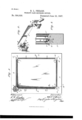
- Figure l represents an inner face View, partly in section, of a window-sash embodying my improvements.
- Fig. 2 represents, on an enlarged seale, a perspective View of devices embodying ⁇ my invention.
- Fig. 3 represents, on an enlarged scale, a cross-section taken on the line III III of Fig. 2.
- l designates the bottom, 2 the top, and 3 the side bars, of a window-sash.
- bracket 6 designates cornerbrackets provided with k arms 7, projecting at right angles to each other, and with the stems or tangs S.
- One of these brackets is fitted in each corner of the sash and forces the pane of glass at such points tightly up against the bead or iiange 5 and holds it in such position by reason of the tact that the stems or tangs 8 of the brackets iit snugly in the holes i of the sash.
- Each arm of said brackets is provided with a cylindrical hole 9 and a narrow or contracted mouth 10 for the same.
- Il designates clamping-strips, which are adapted to connect the corner-brackets and clamp the pane of glass squarely against the flange or bead 5 for its entire length.
- Each strip ll in cross-section corresponds to the form of the arms 7 of the brackets, which are preferably of ornamental configuration.
- top and bottom strips l1 in length are equal to the distance between the horizontal arms of the brackets, while the side strips ll are equal to the distance between the vertical arms of the said brackets, as shown clearly in Fig. l.
- Each strip is provided at its ends with trunnions or pins l2 of elongated form, so that they may be slipped through the mouths l0 of the opposing arms of the brack ets and into the cylindrical cavities 9which in diameter slightly exceed the greatest diameter of said elongated pins in order that the latter may turn therein without lateral play or movement, that the outer edges of said strips when swung from the position shown in dotted lines, Fig.
- brackets iitting in the corners vices may be employed advantageously in connection With glass doors for book-cases and for removably securing in frames sheets of material not necessarily transparent.
Landscapes
- Engineering & Computer Science (AREA)
- Civil Engineering (AREA)
- Structural Engineering (AREA)
- Securing Of Glass Panes Or The Like (AREA)
Description
(No Model.)V
R. L. PHEARS. WINDOW PANE SBGURING DEVICE. No. 584,828.
atented'June z2, 189V.
ilnrTnn STaTns FaTnnT Tries.
ROBERT Il. PHIJARS, OF KANSAS CITY, MISSOURI.
iNINDOVV-PANE-SECURING DEVICE.
Y SPECIFUATION forming part of Letters Patent No. 584,828, dated June 22, 1897. Application filed February 23,1897. Serial No. 624,594. (No model.)
'h all whom it may concern/f Be it known that I, ROBERT L. PHEARS, of Kansas Oity, Jackson county, Missouri, have invented certain new and useful Improvements in WindowlPane-Securing Devices, of which the following is a full, clear, and exact description, reference being had to the accompanyin drawings, forming a part thereof.
My invention relates to window-pane-securing devices, and my object is to produce devices of this character whereby a pane of glass may be clamped and secured quickly and easily in position by a novice or ineXperienced person in the trade or art to which the invention appertains.
A further object of the invention is to produce devices ot' this character which obviato the use of putty entirely, and of screws, if desired.
A further object is to produce devices of this character which are simple, strong, durable, and inexpensive of manufacture.
To these ends the invention consists in certain novel and peculiar features of construction and combinations of parts,as will be hereinafter described and claimed.
In order that the invention may be fully understood, I will proceed to describe it with reference to the accompanying drawings, in whichj Figure l represents an inner face View, partly in section, of a window-sash embodying my improvements. Fig. 2 represents, on an enlarged seale,a perspective View of devices embodying` my invention. Fig. 3 represents, on an enlarged scale, a cross-section taken on the line III III of Fig. 2.
In the said drawings, l designates the bottom, 2 the top, and 3 the side bars, of a window-sash.
4 designates holes which are drilled into said sashat its four corners, said holes ex tending at angles of forty-five degrees.
5 designates an annular flange or bead of the windowsash, against which the pane of glass rests.
6 designates cornerbrackets provided with k arms 7, projecting at right angles to each other, and with the stems or tangs S. One of these brackets is fitted in each corner of the sash and forces the pane of glass at such points tightly up against the bead or iiange 5 and holds it in such position by reason of the tact that the stems or tangs 8 of the brackets iit snugly in the holes i of the sash. Each arm of said brackets is provided with a cylindrical hole 9 and a narrow or contracted mouth 10 for the same.
Il designates clamping-strips, which are adapted to connect the corner-brackets and clamp the pane of glass squarely against the flange or bead 5 for its entire length. Each strip ll in cross-section corresponds to the form of the arms 7 of the brackets, which are preferably of ornamental configuration.
rThe top and bottom strips l1 in length are equal to the distance between the horizontal arms of the brackets, while the side strips ll are equal to the distance between the vertical arms of the said brackets, as shown clearly in Fig. l. Each strip is provided at its ends with trunnions or pins l2 of elongated form, so that they may be slipped through the mouths l0 of the opposing arms of the brack ets and into the cylindrical cavities 9which in diameter slightly exceed the greatest diameter of said elongated pins in order that the latter may turn therein without lateral play or movement, that the outer edges of said strips when swung from the position shown in dotted lines, Fig. 3, to that` shown in full lines, same iigure, shall bear firmly and squarely against the glass and clamp the latter tightly against the bead or flange of the sash. In order to accomplish this, the strips are disposed parallel with the glass, as indicated in Fig. 2 and in dotted lines in Fig. l, and then pushed in the proper direct-ion until said elongated trunnions or pins l2 have wholly entered the cylindrical cavities of the opposing arms of the brackets. The outer faces of the strips are now disposed at right angles to the bead or flange 5, as indica-ted also in Fig. 3, and the necessarily-rounded corners 13 of said strip are opposed to the glass. The strip is then grasped and, supposing it to be the bottom strip, swung downwardly land away from the glass, as indicated by the arrow in Fig. 3. As this operation takes place tle rounded corner of said strip commences to push the glass toward the bead or flange 5, and owing to the fact that the curve of said shoulder is eccentric of the axis of said pin and the cavity 9 this pressure on IOO the glass is increased as the rotatable operation of the strip continues until by the time the outer face of the strip bears against the glass the latter, as hereinbefore stated, is clamped tightly and iirmly secured against said bead or flange 5. Thejoint thus made is so close that it is air and Water tight and the necessity for using putty is entirely obviated.
For small windows, such as car-Windows and the like, Where the strips 1l are comparatively short, it Will be undesirable and unnecessary to employ screws for securing said strips to the sash at intermediate points, but for large Windows and large panes it may be desirable to secure said strips at intermediate points, as indicated by the screws I4 in Fig. l.
Should it be necessary at any time to replace a broken glass, it is obvious that an unskilled person, by inserting` a screw-driver under the edges of said strips, may swing them back to positions parallel With the glass, lift them from position, extract the corner brackets or two or more of them, and then remove the glass and replace it with a perfect one. The brackets are then replaced and the strips resecured in position, as before described.
It is to be understood, of course, that While direct reference is made in this description to securing Window-glasses in position, it is my intention to apply these devices in various other connections For instance, these dei With a bead or iiange, against which a pane of glass rests, of brackets iitting in the corners vices may be employed advantageously in connection With glass doors for book-cases and for removably securing in frames sheets of material not necessarily transparent.
From the above description it Will be apparent that I have produced devices for securing Window-panes in position which embody the features of advantage enumera-ted in the statement of invention, and it is to be understood that I may vary the form, proportion, and detail construction of the parts in some degree Without departing from the spirit and scope of my invention.
Having thus described the invention, what I claim as new, and desire to secure by Letters Patent, is-
` glass rests, of brackets fitting in the corners yclamp the glass firmly against the bead or g flange, substantially as described.
and clamping the glass rmly against said bead or iiange, for the purpose set forth.
2. The combination With a sash provided with a bead or flange, against which a pane of of the sash and provided with pins project- 6o ing into holes in the sash, and clamping-strips connecting and carried by said brackets and clamping the glass firmly against said bead or flange, for the purpose set forth.
3. The combination With a sash provided with a iiange or bead against which a pane of glass rests, of brackets secured in the corners of the sash, and provided With cylindrical i glass rests, of brackets secured in the corners of said sash and provided with cylindrical openings having contracted mouths, and
; clamping-strips connecting said brackets and provided With elongated trunnions Which fit snugly and rotatably in said openings7 and 5. The colnbination With a sash provided of the sash and provided with cylindrical openings having contracted mouths, and clamping-strips having rounded corners and provided with elongated trunnions arranged eccentrically of said corners, and iitting rotatably and snugly in the openings of said 9o 1 brackets, substantially as described.
In testimony whereof I atiix my signature in the presence of two Witnesses.
ROBERT L. PIIEARS.
Witnesses:
G. Y. THORPE, M. R. REMLEY.
Publications (1)
| Publication Number | Publication Date |
|---|---|
| US584828A true US584828A (en) | 1897-06-22 |
Family
ID=2653498
Family Applications (1)
| Application Number | Title | Priority Date | Filing Date |
|---|---|---|---|
| US584828D Expired - Lifetime US584828A (en) | Indow-pane-securing device |
Country Status (1)
| Country | Link |
|---|---|
| US (1) | US584828A (en) |
-
0
- US US584828D patent/US584828A/en not_active Expired - Lifetime
Similar Documents
| Publication | Publication Date | Title |
|---|---|---|
| US2113753A (en) | Window attachment | |
| US133359A (en) | Improvement in hanging sliding doors | |
| US94331A (en) | Improved double window | |
| US642902A (en) | Sash-center. | |
| US1268554A (en) | Casement-window. | |
| US602361A (en) | Window | |
| US124050A (en) | Improvement in combined blind-openers and slat-regulators | |
| US185100A (en) | Improvement in window-blinds | |
| US203820A (en) | Improvement in window-sashes | |
| US869466A (en) | Window construction. | |
| US565774A (en) | jesse | |
| US189384A (en) | Improvement in window-sashes | |
| US380747A (en) | Window-screen | |
| US1032143A (en) | Window-sash. | |
| US108131A (en) | Improvement in sash-cord fasteners | |
| US792375A (en) | Glass-framing attachment for window-sashes. | |
| US491310A (en) | Window | |
| US1202103A (en) | Combination came and stop-bead. | |
| US958992A (en) | Window-sash. | |
| US96507A (en) | Improved window | |
| US1147361A (en) | Pivoted door. | |
| US599251A (en) | Sash-hinge | |
| US125755A (en) | Improvement in ventilators for windows | |
| US1168491A (en) | Window screen and sash locker. | |
| US975719A (en) | Window-sash. |