US5845802A - Grease cartridge carrier - Google Patents
Grease cartridge carrier Download PDFInfo
- Publication number
- US5845802A US5845802A US08/874,534 US87453497A US5845802A US 5845802 A US5845802 A US 5845802A US 87453497 A US87453497 A US 87453497A US 5845802 A US5845802 A US 5845802A
- Authority
- US
- United States
- Prior art keywords
- cap
- carrier
- side wall
- cylindrical
- slot
- Prior art date
- Legal status (The legal status is an assumption and is not a legal conclusion. Google has not performed a legal analysis and makes no representation as to the accuracy of the status listed.)
- Expired - Fee Related
Links
Images


Classifications
-
- F—MECHANICAL ENGINEERING; LIGHTING; HEATING; WEAPONS; BLASTING
- F16—ENGINEERING ELEMENTS AND UNITS; GENERAL MEASURES FOR PRODUCING AND MAINTAINING EFFECTIVE FUNCTIONING OF MACHINES OR INSTALLATIONS; THERMAL INSULATION IN GENERAL
- F16N—LUBRICATING
- F16N3/00—Devices for supplying lubricant by manual action
- F16N3/10—Devices for supplying lubricant by manual action delivering grease
- F16N3/12—Grease guns
-
- B—PERFORMING OPERATIONS; TRANSPORTING
- B65—CONVEYING; PACKING; STORING; HANDLING THIN OR FILAMENTARY MATERIAL
- B65D—CONTAINERS FOR STORAGE OR TRANSPORT OF ARTICLES OR MATERIALS, e.g. BAGS, BARRELS, BOTTLES, BOXES, CANS, CARTONS, CRATES, DRUMS, JARS, TANKS, HOPPERS, FORWARDING CONTAINERS; ACCESSORIES, CLOSURES, OR FITTINGS THEREFOR; PACKAGING ELEMENTS; PACKAGES
- B65D41/00—Caps, e.g. crown caps or crown seals, i.e. members having parts arranged for engagement with the external periphery of a neck or wall defining a pouring opening or discharge aperture; Protective cap-like covers for closure members, e.g. decorative covers of metal foil or paper
- B65D41/02—Caps or cap-like covers without lines of weakness, tearing strips, tags, or like opening or removal devices
- B65D41/04—Threaded or like caps or cap-like covers secured by rotation
- B65D41/06—Threaded or like caps or cap-like covers secured by rotation with bayonet cams, i.e. removed by first pushing axially to disengage the cams and then rotating
Definitions
- the invention is in the field of packaging containers accommodating cartridges storing grease, oil and other flowable products.
- Grease and lubricants are stored in cylindrical cartridges used with grease guns which dispense grease to selected locations.
- the cartridges are marketed as individual products and in groups.
- B. J. Gregory in U.S. Pat. No. Des. 308,025 shows a design of a grease cartridge package having a box with an open front. Four grease cartridges are contained within the box. The removal of one grease cartridge from the box allows the remaining cartridges to fall out of the box into dirt, dust and other contaminants.
- Tractor trailer vehicles have fifth wheel attachments coupling the tractor to the trailer.
- the facing surfaces of the fifth wheel attachments must be lubricated to reduce wear and friction.
- Grease guns carried in the tractor are used to spread grease on the facing surfaces of the fifth wheel attachments.
- D. D. Spiers in U.S. Pat. No. 4,913,263 discloses the use of grease guns for lubricating fifth wheel attachments coupling tractors to trailers and an envelope of grease placed between the plates of the fifth wheel attachment. The walls of the envelope rupture between the plates allowing the grease to spread between the plates.
- Additional grease cartridges or envelopes of grease are stored in the tractor of in a tool box.
- the cartridges being cylindrical can rock and roll in storage compartments. Caps on the cartridges can dislodge causing grease to spill and contaminate the grease with dust, dirt and other foreign materials.
- the walls of the cartridges can also be cut thereby allowing grease to escape into the storage compartment.
- the preferred embodiment of the carrier has body having a cylindrical chamber for accommodating a conventional grease cartridge.
- a cap locked onto the body retains the grease cartridge in the chamber.
- the body has a plurality of elongated generally flat and rectangular outer surfaces.
- the outer surfaces have an octagonal pattern with each surface having substantially the same area.
- the cap has a side wall with outside surfaces that are coextensive with the outer surfaces of the body. The cap is releasably attached to the body with cooperating pins and angle slots on adjacent portions of the body and cap.
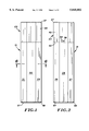
- FIG. 1 is a front elevational view of the grease cartridge carrier of the invention., the rear elevational view is a mirror image of FIG. 1;
- FIG. 2 is a side elevational view of the right side thereof
- FIG. 3 is a side elevational view of the left side thereof
- FIG. 4 is a sectional view taken along line 4--4 of FIG. 3;
- FIG. 5 is a top plan view thereof
- FIG. 6 is a sectional view taken along line 6--6 of FIG. 1;
- FIG. 7 is a sectional view taken along line 7--7 of FIG. 4;
- FIG. 8 is an enlarged side view of the releasable lock securing the cap to the body of the grease cartridge carrier;
- FIG. 9 is a sectional view taken along line 9--9 of FIG. 8;
- FIG. 10 is a side elevational view of a grease cartridge
- FIG. 11 is a longitudinal sectional view similar to FIG. 4 of the carrier accommodating a grease cartridge.
- the grease cartridge carrier 15, shown in FIGS. 1 to 4, is a durable and lightweight container for storing a conventional grease cartridge 16.
- cartridge 16 has a cylindrical, plastic side wall 17 joined to a bottom member 18.
- a cup-shaped cap 19 closes the top of wall 17.
- Cartridge 16 has a cylindrical chamber filled with a semi-solid lubricant 22, known as red grease.
- Example of a grease cartridge for a grease fun is disclosed by A. Clawson in U.S. Pat. No. 1,674,542 and J. B. Freestone in U.S. Pat. No. 2,506,204.
- Cartridge 16 is used with a grease gun to lubricate truck and trailer parts and machines that require lubrication.
- cartridges are stored in tool chests and storage areas of a truck.
- the cylindrical shape of cartridge 16 permits it to rock and roll in storage areas.
- Cap 19 can be dislodged causing grease to escape into the storage area.
- Carrier 15 encloses cartridge 16 to prevent damage tot he cartridge and retain cap 19 of side wall 17 so as to eliminate contamination of the grease and escape of grease from the cartridge.
- carrier 15 has a body 22 and cap 23 surrounding a closed internal chamber 24 for accommodating grease cartridge 16.
- Body 22 has a plurality of elongated generally flat and rectangular outer surfaces 26, 27, 28, 29, 30, 31, 32 and 33.
- Surfaces 26-33 have substantially the same areas and are arranged in an octagonal pattern as shown in FIG. 6.
- the outer surfaces of body can have other non-cylindrical shapes including three, four, five and six sides.
- Surfaces 26-33 when positioned on a support minimize rolling and movement of the body relative to the support.
- Surfaces 26-33 are on the outside of a side wall 34 of the carrier.
- Wall 34 has an inside cylindrical surface 36 around chamber 24.
- Side wall 34 is joined to a bottom wall 37 closing the lower end of the chamber 24.
- Bevel edges 38 are at the lower ends of surfaces 26-33 and outer periphery of bottom wall 37.
- upper end of side wall 34 has a rim or cylindrical flange 39 with an outer cylindrical surface 41 and a circular top edge 42.
- Flange 39 has a width about one half of the width of side wall 34.
- An annular shoulder 43 on side wall 34 surrounds flange 39.
- Side wall 34, bottom wall 37 and flange 39 are a one-piece structure of rigid material, such as plastic, metal or composite materials.
- Cap 23 has a side wall 44 with eight outside surfaces 45, a flat top wall 46 and a beveled edge 47 surrounding top wall 46 at the upper ends of outside surfaces 45.
- Surface 45 each have a rectangular shape with a width the same as the surfaces 26-33 on body 34.
- the inside of side wall 44 has a cylindrical inside surface 48 corresponding to surface 36 of body 34.
- the bottom of side wall 44 has a downwardly directed lip 49 with an inside cylindrical surface 51, an upper edge 52 and lower edge 53, shown in FIG. 9.
- Lip 49 has a width of about one half the width of side wall 44 and telescopes over flange 39.
- Cap 23 is locked on body 22 with a pair of pins 54 and 56 secured to flange 39 projected inwardly into slot 57 and 58 inside wall lip 49 of cap 23.
- each slot 57 and 58 has a upward longitudinal inlet open to lower edge 53 and a downwardly inclined circumferential blind section 59.
- a detent 61 on wall 44 projects into slot section 59 to lock cap 23 on body 22.
- the flat outside faces of cap 23 are in registration with the surfaces 26 to 33 of body 22. The aligned flat surfaces of body 22 and cap 23 minimizes rolling of carrier 15 in a storage space.
- grease cartridge 16 is inserted into chamber 24 with the cap end extended through the open end of body 22.
- Cap 23 is placed over the end 19 of cartridge 16.
- the inlets of the slots 57 and 58 are aligned with pins 54 and 56 to allow cap 23 to be telescoped over annular flange 39 of body 22.
- Cap 23 is then turned in a clockwise direction to move pins 54 and 56 into slot sections 59 past detentes 61.
- the detentes 61 hold pins 54 and 56 in the blind ends of slots sections 59.
- the downwardly inclined top edges of the slot sections 59 engage pins 54 and 56 to force cap 23 tight against shoulder 42 so as to prevent dust, dirt and particulate matter from flowing into chamber 24.
- Cap 23 is removed from body 22 by turning cap 23 counterclockwise relative to body 22 to align pins 54 and 56 with slat sections 58. Cap 23 is then pulled from body 22. Grease cartridge 16 can be withdrawn from chamber 24 by gripping the upper end of the cartridge that extends out of body 22.
Landscapes
- Engineering & Computer Science (AREA)
- General Engineering & Computer Science (AREA)
- Mechanical Engineering (AREA)
- Packages (AREA)
Abstract
Description
Claims (28)
Priority Applications (1)
| Application Number | Priority Date | Filing Date | Title |
|---|---|---|---|
| US08/874,534 US5845802A (en) | 1997-06-13 | 1997-06-13 | Grease cartridge carrier |
Applications Claiming Priority (1)
| Application Number | Priority Date | Filing Date | Title |
|---|---|---|---|
| US08/874,534 US5845802A (en) | 1997-06-13 | 1997-06-13 | Grease cartridge carrier |
Publications (1)
| Publication Number | Publication Date |
|---|---|
| US5845802A true US5845802A (en) | 1998-12-08 |
Family
ID=25364023
Family Applications (1)
| Application Number | Title | Priority Date | Filing Date |
|---|---|---|---|
| US08/874,534 Expired - Fee Related US5845802A (en) | 1997-06-13 | 1997-06-13 | Grease cartridge carrier |
Country Status (1)
| Country | Link |
|---|---|
| US (1) | US5845802A (en) |
Cited By (5)
| Publication number | Priority date | Publication date | Assignee | Title |
|---|---|---|---|---|
| US20050011894A1 (en) * | 2003-07-14 | 2005-01-20 | Guenter Eberle | Closure device for a centrifuge tube |
| US6874599B1 (en) * | 2002-12-11 | 2005-04-05 | Fifth wheel lubrication system | |
| WO2007132283A1 (en) * | 2006-05-16 | 2007-11-22 | Kenneth Martin | Lubricant cartridge storage device |
| US20080283431A1 (en) * | 2007-05-14 | 2008-11-20 | Joss Michael S | Grease cartridge management system |
| WO2019099325A1 (en) * | 2017-11-14 | 2019-05-23 | Kush Bottles, Inc. | Child-resistant container |
Citations (20)
| Publication number | Priority date | Publication date | Assignee | Title |
|---|---|---|---|---|
| US1674542A (en) * | 1927-01-06 | 1928-06-19 | Clawson Archie | Grease cartridge for grease guns |
| US1832669A (en) * | 1930-09-11 | 1931-11-17 | Adolph A Thomas | Self-sealing cap for containers |
| US2506204A (en) * | 1946-10-11 | 1950-05-02 | Freestone Joseph Blaine | Grease dispenser |
| US3071282A (en) * | 1960-04-20 | 1963-01-01 | Harold Horton Jr | Insulated container |
| US3312336A (en) * | 1964-01-13 | 1967-04-04 | Whitman Publishing Company | Coin tube |
| US3501063A (en) * | 1968-04-05 | 1970-03-17 | Superior Mfg Co | Plunger assembly for multiloading hand grease guns |
| US4006837A (en) * | 1974-10-30 | 1977-02-08 | Wheeling Closure Corporation | Container closure |
| US4185756A (en) * | 1977-11-28 | 1980-01-29 | American Flange & Manufacturing Co. | Dispensing package and method |
| US4257526A (en) * | 1978-08-21 | 1981-03-24 | Coors Container Company | Bottle closure and finish |
| US4387821A (en) * | 1979-12-20 | 1983-06-14 | A.M.S. (Ateliers De Moulage Specialise) | Stopping device for bottle |
| US4482073A (en) * | 1982-11-18 | 1984-11-13 | M.B.F. Plastiques | System for retaining a cap with respect to the neck of a recipient |
| FR2567104A1 (en) * | 1983-09-27 | 1986-01-10 | Geiger Reinold | Stopper device for flask |
| US4856652A (en) * | 1988-04-04 | 1989-08-15 | Chrysler Motors Corporation | Self-contained oil source and drain package |
| US4913263A (en) * | 1988-10-31 | 1990-04-03 | Spiers Dennis D | Grease packet for fifth wheels |
| USD308025S (en) | 1988-05-13 | 1990-05-22 | Witco Corporation | Grease cartridge package |
| US4955480A (en) * | 1989-07-21 | 1990-09-11 | Sexton Wilson C | Portable insulated carrier |
| DE4001609A1 (en) * | 1990-01-20 | 1991-07-25 | Wilhelm Hogh | Pressurised container for tennis balls - has piston attached to container lid to achieve required pressure |
| US5072850A (en) * | 1991-04-25 | 1991-12-17 | Gagnon Robert M | Receptacle for foodstuffs and the like |
| US5160021A (en) * | 1991-07-30 | 1992-11-03 | Barry Sibley | Leak-proof cylindrical container for the transport of diagnostic specimens or dangerous substances |
| US5466020A (en) * | 1994-12-30 | 1995-11-14 | Valleylab Inc. | Bayonet connector for surgical handpiece |
-
1997
- 1997-06-13 US US08/874,534 patent/US5845802A/en not_active Expired - Fee Related
Patent Citations (20)
| Publication number | Priority date | Publication date | Assignee | Title |
|---|---|---|---|---|
| US1674542A (en) * | 1927-01-06 | 1928-06-19 | Clawson Archie | Grease cartridge for grease guns |
| US1832669A (en) * | 1930-09-11 | 1931-11-17 | Adolph A Thomas | Self-sealing cap for containers |
| US2506204A (en) * | 1946-10-11 | 1950-05-02 | Freestone Joseph Blaine | Grease dispenser |
| US3071282A (en) * | 1960-04-20 | 1963-01-01 | Harold Horton Jr | Insulated container |
| US3312336A (en) * | 1964-01-13 | 1967-04-04 | Whitman Publishing Company | Coin tube |
| US3501063A (en) * | 1968-04-05 | 1970-03-17 | Superior Mfg Co | Plunger assembly for multiloading hand grease guns |
| US4006837A (en) * | 1974-10-30 | 1977-02-08 | Wheeling Closure Corporation | Container closure |
| US4185756A (en) * | 1977-11-28 | 1980-01-29 | American Flange & Manufacturing Co. | Dispensing package and method |
| US4257526A (en) * | 1978-08-21 | 1981-03-24 | Coors Container Company | Bottle closure and finish |
| US4387821A (en) * | 1979-12-20 | 1983-06-14 | A.M.S. (Ateliers De Moulage Specialise) | Stopping device for bottle |
| US4482073A (en) * | 1982-11-18 | 1984-11-13 | M.B.F. Plastiques | System for retaining a cap with respect to the neck of a recipient |
| FR2567104A1 (en) * | 1983-09-27 | 1986-01-10 | Geiger Reinold | Stopper device for flask |
| US4856652A (en) * | 1988-04-04 | 1989-08-15 | Chrysler Motors Corporation | Self-contained oil source and drain package |
| USD308025S (en) | 1988-05-13 | 1990-05-22 | Witco Corporation | Grease cartridge package |
| US4913263A (en) * | 1988-10-31 | 1990-04-03 | Spiers Dennis D | Grease packet for fifth wheels |
| US4955480A (en) * | 1989-07-21 | 1990-09-11 | Sexton Wilson C | Portable insulated carrier |
| DE4001609A1 (en) * | 1990-01-20 | 1991-07-25 | Wilhelm Hogh | Pressurised container for tennis balls - has piston attached to container lid to achieve required pressure |
| US5072850A (en) * | 1991-04-25 | 1991-12-17 | Gagnon Robert M | Receptacle for foodstuffs and the like |
| US5160021A (en) * | 1991-07-30 | 1992-11-03 | Barry Sibley | Leak-proof cylindrical container for the transport of diagnostic specimens or dangerous substances |
| US5466020A (en) * | 1994-12-30 | 1995-11-14 | Valleylab Inc. | Bayonet connector for surgical handpiece |
Cited By (5)
| Publication number | Priority date | Publication date | Assignee | Title |
|---|---|---|---|---|
| US6874599B1 (en) * | 2002-12-11 | 2005-04-05 | Fifth wheel lubrication system | |
| US20050011894A1 (en) * | 2003-07-14 | 2005-01-20 | Guenter Eberle | Closure device for a centrifuge tube |
| WO2007132283A1 (en) * | 2006-05-16 | 2007-11-22 | Kenneth Martin | Lubricant cartridge storage device |
| US20080283431A1 (en) * | 2007-05-14 | 2008-11-20 | Joss Michael S | Grease cartridge management system |
| WO2019099325A1 (en) * | 2017-11-14 | 2019-05-23 | Kush Bottles, Inc. | Child-resistant container |
Similar Documents
| Publication | Publication Date | Title |
|---|---|---|
| US4789017A (en) | Funnel with storage system | |
| US5499561A (en) | Oil filter wrench and packaging therefor | |
| US6536687B1 (en) | Mixing cup adapting assembly | |
| US5381940A (en) | Tray combinations | |
| DE3782054T2 (en) | PRESSURIZABLE TRANSPORT CONTAINER FOR CHEMICAL PRODUCTS. | |
| US5845802A (en) | Grease cartridge carrier | |
| US20250085093A1 (en) | Interlocking stacking ammunition containers | |
| US5330227A (en) | Storable truck bed weights for improved traction and handling | |
| AU2011359027A1 (en) | Transport and presentation box | |
| EP0972616A2 (en) | Repair kit and its portable container | |
| US5941432A (en) | Storage container for emergency fuel | |
| US5330055A (en) | Package assembly for separately packaging, displaying, and dispensing a plurality of articles | |
| US6880589B2 (en) | Container for collecting and transporting drained oil | |
| US2996213A (en) | Containers | |
| US6041959A (en) | Chemical waste collection and disposal apparatus | |
| US3602397A (en) | Filling and emptying means for a flexible sac for holding a product to be dispensed | |
| US20110155600A1 (en) | Beverage can and bottle container | |
| BE1007118A6 (en) | Device for packaging and transporting containers | |
| US20200361688A1 (en) | Liquid storage containers and systems | |
| ES2303234T3 (en) | PACKING ASSEMBLY, IN PARTICULAR A RETURNABLE TYPE PACKING ASSEMBLY. | |
| US1343374A (en) | Ammunition-receptacle | |
| EP1424288B1 (en) | Device for packing, storage, transportation and supply of pulverulent products | |
| EP1563873A2 (en) | Modular fire-fighting unit for vehicles | |
| AU2004261309B2 (en) | Accessory for a grease gun | |
| USD1009708S1 (en) | Towing system |
Legal Events
| Date | Code | Title | Description |
|---|---|---|---|
| AS | Assignment |
Owner name: PLASTIC SPECIALTIES, L.L.C., MINNESOTA Free format text: ASSIGNMENT OF ASSIGNORS INTEREST;ASSIGNORS:BRUNS, STEVEN A.;BRUNS, MARK W.;REEL/FRAME:009581/0961 Effective date: 19981105 |
|
| REMI | Maintenance fee reminder mailed | ||
| LAPS | Lapse for failure to pay maintenance fees | ||
| STCH | Information on status: patent discontinuation |
Free format text: PATENT EXPIRED DUE TO NONPAYMENT OF MAINTENANCE FEES UNDER 37 CFR 1.362 |
|
| FP | Lapsed due to failure to pay maintenance fee |
Effective date: 20021208 |
|
| AS | Assignment |
Owner name: PRIDE SOLUTIONS, LLC, MINNESOTA Free format text: ASSIGNMENT OF ASSIGNORS INTEREST;ASSIGNORS:BRUNS, STEVEN A.;BRUNS, MARK W.;REEL/FRAME:014556/0519 Effective date: 20021101 |