US5845452A - Roof anchor for safety equipment - Google Patents
Roof anchor for safety equipment Download PDFInfo
- Publication number
- US5845452A US5845452A US08/921,120 US92112097A US5845452A US 5845452 A US5845452 A US 5845452A US 92112097 A US92112097 A US 92112097A US 5845452 A US5845452 A US 5845452A
- Authority
- US
- United States
- Prior art keywords
- anchor
- roof
- coupling member
- leg portions
- approved
- Prior art date
- Legal status (The legal status is an assumption and is not a legal conclusion. Google has not performed a legal analysis and makes no representation as to the accuracy of the status listed.)
- Expired - Fee Related
Links
- 230000008878 coupling Effects 0.000 claims abstract description 55
- 238000010168 coupling process Methods 0.000 claims abstract description 55
- 238000005859 coupling reaction Methods 0.000 claims abstract description 55
- 230000015572 biosynthetic process Effects 0.000 claims abstract description 8
- 238000005755 formation reaction Methods 0.000 claims description 7
- 238000010276 construction Methods 0.000 abstract description 7
- 238000009436 residential construction Methods 0.000 abstract description 2
- 230000002093 peripheral effect Effects 0.000 description 5
- 229910000831 Steel Inorganic materials 0.000 description 4
- 239000010959 steel Substances 0.000 description 4
- 238000004080 punching Methods 0.000 description 2
- 238000003466 welding Methods 0.000 description 2
- 229910000840 Capped steel Inorganic materials 0.000 description 1
- 229910001335 Galvanized steel Inorganic materials 0.000 description 1
- HCHKCACWOHOZIP-UHFFFAOYSA-N Zinc Chemical compound [Zn] HCHKCACWOHOZIP-UHFFFAOYSA-N 0.000 description 1
- 230000007797 corrosion Effects 0.000 description 1
- 238000005260 corrosion Methods 0.000 description 1
- 230000000694 effects Effects 0.000 description 1
- 239000008397 galvanized steel Substances 0.000 description 1
- 231100001261 hazardous Toxicity 0.000 description 1
- 238000012423 maintenance Methods 0.000 description 1
- 239000002184 metal Substances 0.000 description 1
- 229910052751 metal Inorganic materials 0.000 description 1
- 239000000843 powder Substances 0.000 description 1
- 230000001105 regulatory effect Effects 0.000 description 1
- 229910052725 zinc Inorganic materials 0.000 description 1
- 239000011701 zinc Substances 0.000 description 1
Images


Classifications
-
- E—FIXED CONSTRUCTIONS
- E04—BUILDING
- E04D—ROOF COVERINGS; SKY-LIGHTS; GUTTERS; ROOF-WORKING TOOLS
- E04D15/00—Apparatus or tools for roof working
-
- E—FIXED CONSTRUCTIONS
- E04—BUILDING
- E04G—SCAFFOLDING; FORMS; SHUTTERING; BUILDING IMPLEMENTS OR AIDS, OR THEIR USE; HANDLING BUILDING MATERIALS ON THE SITE; REPAIRING, BREAKING-UP OR OTHER WORK ON EXISTING BUILDINGS
- E04G21/00—Preparing, conveying, or working-up building materials or building elements in situ; Other devices or measures for constructional work
- E04G21/32—Safety or protective measures for persons during the construction of buildings
- E04G21/3261—Safety-nets; Safety mattresses; Arrangements on buildings for connecting safety-lines
- E04G21/3276—Arrangements on buildings for connecting safety-lines
Definitions
- This invention relates to the art of safety apparatus, and more particularly to a new and improved roof anchor for safety equipment.
- the present invention provides an anchor for securing a safety line to a roof having a pair of sloping portions defining an angle therebetween.
- the anchor preferably is in the form of a two person permanent roof anchor for use by the residential construction industry as an anchor point from which construction or contractor personnel may attach an approved life line to which an approved personal fall arrest safety device may be attached.
- the anchor comprises anchor bracket means having a pair of leg portions disposed at an angle in relation to the angle between the sloping portions of a roof so that the leg portions lie along the roof portions, and means for attaching the leg portions to the roof portions.
- the anchor further comprises at least one coupling member and means for hingedly connecting the coupling member to the anchor bracket means on one of the leg portions, the coupling member having means thereon for connection to one end of a safety line, the other end of which is connected to approved safety equipment in the form of an approved personal fall arrest safety device for use by a person working on a roof.
- a pair of coupling members are provided, each hingedly connected in a unidirectional manner to a corresponding one of the anchor bracket leg portions, the coupling members in turn being adapted for connection via two safety lines to a pair of fall arrest safety devices.
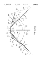
- FIG. 1 is an elevational view of a roof anchor according to the present invention as it would appear in use;
- FIG. 2 is a plan view of the roof anchor of FIG. 1;
- FIG. 3 is a fragmentary plan view showing one of the leg portions of the anchor bracket of the roof anchor of FIG. 1;
- FIG. 4 is a plan view of one of the hinge brackets in the roof anchor of FIG. 1;
- FIG. 5 is an end elevational view of the hinge bracket of FIG. 4;
- FIG. 6 is a side elevational view of the hinge bracket of FIG. 4;
- FIG. 7 is a plan view of one of the coupling members in the roof anchor of FIG. 1;
- FIG. 8 is an end elevational view of the coupling member of FIG. 7.
- FIG. 9 is a side elevational view of the coupling member of FIG. 7.
- an anchor 10 for securing at least one safety line to a roof represented diagrammatically at 12.
- Each safety line is secured to a personal fall arrest safety device (not shown) such as an approved safety belt, harness or the like worn by persons working on a roof.
- Roof 12 includes a pair of sloping portions 14, 16 extending from an uppermost part 18 in a conventional manner. The roof sloping portions define an angle therebetween designated 20 in FIG. 1.
- the anchor 10 comprises anchor bracket means generally designated 24 having a pair of leg portions 26 and 28 extending from a central portion 30. As shown in FIG. 1, leg portions 26 and 28 are disposed each at an angle to central portion 30 in relation to the angle 20 of sloping roof portions 14 and 16 so that leg portions 26 and 28 lie along roof portions 14 and 16, respectively. In the roof anchor 10 illustrated in FIG. 1, leg portion 26 defines an angle 34 with respect to a line 36 disposed perpendicular to central portion 30, and leg portion 28 defines an angle 38 with respect to line 36.
- Anchor bracket means 24 is formed from a plate-like part die cut or punched from a sheet of metal such as steel and bent or otherwise formed to have the shape illustrated in FIG. 1 wherein leg portions 26 and 28 extend at angles from central portion 30.
- Each of the leg portions for example leg portion 28 shown also in FIG. 3, is elongated rectangular in shape having a pair of side edges 44 and 46 which meet an end 48.
- Leg portion 28 is provided with apertures therein to receive fasteners for securing anchor bracket means 24 through the sheathing of a roof and into a supporting joist or rafter.
- a first set of apertures 50 is provided in leg portion 28 near end 48 and a second set of apertures 52 is provided near the junction with bracket central portion 30.
- Leg portion 28 also is provided with a pair of elongated, longitudinally extending slots 54 disposed parallel to edges 44, 46 located near the junction with central portion 30 and for a purpose which will be described.
- Bracket portion 26 is identical to portion 28 having side edges 60 and 62 meeting an end 64, first and second sets of apertures 66 and 68, respectively, and a pair of longitudinally extending slots 70.
- bracket means 24 is punched or die cut from G90/C1008 galvanized steel having a thickness of about 2 mm. so that each leg portion 26 and 28 has a length of about 266.9 mm., central portion 30 has a length of about 63.5 mm. and the common width of leg portions 26, 28 and central portion 30 is about 91.2 mm.
- the anchor 10 further comprises at least one coupling member for connection to one end of an approved safety line appropriately attached to an approved fall arrest safety device and means for hingedly connecting the coupling member to the anchor bracket means 24.
- anchor 10 includes a pair of coupling members 80 and 82 connected by hinge brackets 84 and 86, respectively, to leg portions 26 and 28, respectively, of anchor 10.
- a pair of approved personal fall arrest safety devices represented diagrammatically at 90 and 92 in FIG. 1, are secured to anchor 10, in particular by lines represented diagrammatically at 94 and 96 fastened to coupling members 80 and 82, respectively.
- FIGS. 4-6 show in detail one of the hinge brackets 84, it being understood that bracket 86 is identical to bracket 84.
- Bracket 84 includes a body portion 100 in the form a plate which is generally rectangular in shape having a pair of side edges 102 and 104 joined by a pair of end edges 106 and 108.
- Bracket 84 also includes a pair of hinge defining formations in the form of a pair of flanges 110 and 112 extending from sides 102 and 104 of plate 100 in the same direction and disposed substantially perpendicular to plate 100 and substantially parallel to each other.
- Flanges 110 and 112 are provided with aligned apertures 114 and 116, respectively, extending therethrough for a purpose which will be described.
- Flanges 110 and 112 are of a length, width and thickness so as to extend through slots 70 in leg portion 26 when bracket 84 is installed on leg portion 26 as shown in FIG. 1.
- Bracket 84 is installed on leg portion 26 with body portion 100 contacting the surface of leg portion 26 which faces toward the roof on which anchor 10 is installed and with the hinge defining formations 110 and 112 extending through slots 70 and outwardly from the opposite surface of leg portion 26.
- plate 100 is welded to leg portion 26.
- Bracket 86 on leg portion 28 is identical to bracket 84 having plate-like body 130, hinge defining portions or flanges 132 and 134 extending from body 130 and aligned apertures 136 and 138 in flanges 132 and 134, respectively.
- bracket 84 is punched or die cut from H.S.C.A. steel provided with a clear zinc finish and having a thickness of about 4.0 mm., the flanges 110, 112 being bent or formed to the dispositions shown in FIGS. 4-6 after the cutting or punching operation and after apertures 114, 116 and 120 are drilled therein.
- Plate 100 has a width of about 65.34 mm.
- Bracket 86 is formed in a manner identical to that of bracket 84 and has the same illustrative dimensions.
- FIGS. 7-9 show in detail one of the coupling members 80, it being understood that member 82 is identical to member 80.
- Coupling member 80 includes a plate-like body portion 140, means 142 on one end for connection to one end of an approved safety line, for example line 94 shown in FIG. 1, and means on the opposite end for providing a hinge connection to leg portion 26.
- Body portion 140 is generally rectangular in shape having a pair of side edges 148 and 150 which meet the peripheral edge 152 of a substantially circular end portion 154 provided with an opening 156. Opening 156 enables one end of a safety line, for example line 94 shown in FIG. 1, to be fastened to coupling member 80.
- flanges 164 and 166 are substantially semicircular peripheral edges 168 and 170, respectively, and are provided with openings 172 and 174, respectively, therethrough for a purpose to be described.
- the end of body portion 140 adjacent flanges 164 and 166 is provided with a laterally extending flange 180 for a purpose to be described.
- Flange 180 is disposed substantially perpendicular to the plane of body portion 140 and extends in the same direction as flanges 164 and 166 relative to the plane of body portion 140.
- Coupling member 82 is identical to coupling member 80 having plate-like body portion 190, opening 192 near one and to facilitate fastening to one end of an approved safety line, for example line 96 shown in FIG. 1, flanges with semi-circular edges at the opposite end of body portion 190, one flange 194 and edge 196 being shown in FIG. 1, and a lateral flange 198.
- an approved safety line for example line 96 shown in FIG. 1
- coupling member 80 is punched or die cut from H.S.C.A. steel having a thickness of about 3.5 mm., the flanges 164, 166 and 180 being bent or formed to the dispositions shown in FIGS.
- Coupling member 80 has an overall length of about 127.90 mm measured along the longitudinal axis of member 80 between edge 152 of end portion 154 and the outer surface of flange 180.
- the width of body portion 140 between side edges 148 and 150 is about 38.1 mm.
- Edge 152 is defined by a circle of radius of about 28.6 mm measured from the center of opening 156.
- Flanges 164 and 166 are spaced apart a distance about 57.15 mm measured between the inner surfaces thereof, and each flange 164, 166 has a length of about 25.5 mm and width of about 17.65 mm measured from the inner surface of body portion 140 to the outermost points on the flange peripheral edges 168 and 170. Each flange opening 172 and 174 has a diameter of about 9.5 mm. Flange 180 has a length of about 38.1 mm and a width of about 11.6 mm measured from the inner surface of body portion 140 to the edge of flange 180.
- Coupling member 82 is formed in a manner identical to that of member 80 and has the same illustrative dimensions.
- bracket 84 is installed on leg portion 26 of anchor bracket 24 with body portion 100 contacting the surface of leg portion 26 which faces toward the roof on which anchor 10 is installed and with flanges 110 and 112 extending through slots 70 in leg portion 26. Bracket 84 is fixed to leg portion 26 by fasteners or welding or both as previously described.
- bracket 86 is installed on leg portion 28 of anchor bracket 24 with body portion 130 contacting the surface of leg portion 28 which faces toward the roof on which anchor 10 is installed and with flanges 132 and 134 extending through slots 54 in leg portion 28. Bracket 86 likewise is fixed to leg portion 28 by fasteners or welding or both.
- Coupling number 80 is located so that flanges 164 and 166 are located in the space between flanges 110 and 112 and that the peripheral edges 168 and 170 thereof face toward leg portion 26.
- the apertures 172 and 174 of flanges 164 and 166, respectively, are aligned with the apertures 114 and 116 of flanges 110 and 112, respectively, and a hinge pin 210 is inserted in the aligned apertures and fixed against substantial longitudinal movement in a suitable manner so that it remains in place.
- coupling member 80 is pivotally connected to leg portion 26 for limited pivotal movement about the axis of pin 210.
- each hinge pin 210 and 212 is a rivet capped steel hinge pin having a shank diameter of about 9.15 mm and shank length of about 76.20 mm.
- coupling members 80 and 82 facilitate connection of approved safety lines to members 80 and 82 when anchor 10 is secured to a roof.
- the end of each member for example member 80 shown in FIG. 1, can be lifted or moved away a short distance from anchor bracket leg portion 26 to provide unrestricted access to opening 156 for connection or securement of the end of line 92 to member 80.
- FIG. 1 shows lateral flange 198 of coupling member 82 engaging the surface of leg portion 28 which prevents any further pivotal movement of coupling member 82 in a counter-clockwise direction as viewed in FIG. 1. This prevents the coupling member from being pivoted or swung back to a position where the end would be difficult or impossible to safely reach which could cause potential hazard or danger in a person reaching or stretching in an attempt to swing or move the coupling member back to the normal position.
- Anchor 10 of the present invention once assembled, can be secured to most residential roofs having a peak style construction.
- Anchor 10 is designed to be installed directly over the roof sheathing and secured to a rafter (anchor point) by means of sixteen 2.5 inch screws or ring-shank roofers' nails and is capable of supporting 5,000 pounds as recommended by OSHA and ANSI.
- anchor 10 Once permanently fastened to the roof, anchor 10 may be left in place for use by the home owner and/or contractors using approved safety equipment.
- the anchor 10 of the present invention is not intended for use as a hoist anchor point.
- Anchor 10 requires no caulking when properly installed.
- the safety stop uni-directional anchor rings or coupling members 80 and 82 allow for the safe connection of two approved individual personal fall arrest systems, one on each side of the roof peak.
- Anchor 10 is of heavy duty all steel construction, and the exposed coupling members are powder coated to inhibit corrosion.
- Anchor 10 is designed to meet the requirements of both OSHA (1910.66) and ANSI (Z359.1) standards when used with an approved personal fall arrest system.
Abstract
An anchor for securing a safety line to a roof having a pair of sloping portions defining an angle therebetween. The anchor is in the form of a two person permanent roof anchor for use by the residential construction industry as an anchor point from which construction or contractor personnel may attach an approved life line to which an approved personal fall arrest safety device may be attached. The anchor comprises an anchor bracket having a pair of leg portions disposed at an angle in relation to the angle between the sloping portions of a roof so that the leg portions lie along the roof portions, and fasteners for attaching the leg portions to the roof portions. The anchor further comprises at least one coupling member and a component for hingedly connecting the coupling member to the anchor bracket on one of the leg portions, the coupling member having a formation thereon for connection to one end of a safety line, the other end of which is connected to safety equipment in the form of an approved personal fall arrest safety device for use by a person working on a roof. A pair of coupling members can be provided, each hingedly connected in a unidirectional manner to a corresponding one of the anchor bracket leg portions, the coupling members in turn being adapted for connection via two approved safety lines to a pair of approved fall arrest safety devices.
Description
This invention relates to the art of safety apparatus, and more particularly to a new and improved roof anchor for safety equipment.
Safety systems and devices have been proposed for maintaining the safety of workers positioned on a roof, in particular for preventing roofers, construction workers and others from accidentally falling off roofs during construction, maintenance and other activities. Pitched roofs which have significant pitched portions or severe pitch angles can pose hazardous risks to such workers. The potential danger associated with the pitched roof working environment has become widely recognized, and there has been increased regulatory attention on maintaining safety for workers on pitched roof structures.
It would, therefore, be highly desirable to provide a new and improved anchor which is securable to most roofs having a peak style construction, which is permanently and directly installed on the roof sheathing, which can support weights recommended by OSHA and ANSI standards, and to which at least one and preferably two lifelines can be attached to hold approved personal fall ar rest safety devices.
The present invention provides an anchor for securing a safety line to a roof having a pair of sloping portions defining an angle therebetween. The anchor preferably is in the form of a two person permanent roof anchor for use by the residential construction industry as an anchor point from which construction or contractor personnel may attach an approved life line to which an approved personal fall arrest safety device may be attached. The anchor comprises anchor bracket means having a pair of leg portions disposed at an angle in relation to the angle between the sloping portions of a roof so that the leg portions lie along the roof portions, and means for attaching the leg portions to the roof portions. The anchor further comprises at least one coupling member and means for hingedly connecting the coupling member to the anchor bracket means on one of the leg portions, the coupling member having means thereon for connection to one end of a safety line, the other end of which is connected to approved safety equipment in the form of an approved personal fall arrest safety device for use by a person working on a roof. Preferably a pair of coupling members are provided, each hingedly connected in a unidirectional manner to a corresponding one of the anchor bracket leg portions, the coupling members in turn being adapted for connection via two safety lines to a pair of fall arrest safety devices.
The foregoing and additional advantages and characterizing features of the present invention will become clearly apparent upon a reading of the ensuing detailed description together with the included drawing wherein:
FIG. 1 is an elevational view of a roof anchor according to the present invention as it would appear in use;
FIG. 2 is a plan view of the roof anchor of FIG. 1;
FIG. 3 is a fragmentary plan view showing one of the leg portions of the anchor bracket of the roof anchor of FIG. 1;
FIG. 4 is a plan view of one of the hinge brackets in the roof anchor of FIG. 1;
FIG. 5 is an end elevational view of the hinge bracket of FIG. 4;
FIG. 6 is a side elevational view of the hinge bracket of FIG. 4;
FIG. 7 is a plan view of one of the coupling members in the roof anchor of FIG. 1;
FIG. 8 is an end elevational view of the coupling member of FIG. 7; and
FIG. 9 is a side elevational view of the coupling member of FIG. 7.
Referring to FIG. 1, there is shown an anchor 10 according to the present invention for securing at least one safety line to a roof represented diagrammatically at 12. Each safety line, in turn, is secured to a personal fall arrest safety device (not shown) such as an approved safety belt, harness or the like worn by persons working on a roof. Roof 12 includes a pair of sloping portions 14, 16 extending from an uppermost part 18 in a conventional manner. The roof sloping portions define an angle therebetween designated 20 in FIG. 1.
The anchor 10 according to the present invention comprises anchor bracket means generally designated 24 having a pair of leg portions 26 and 28 extending from a central portion 30. As shown in FIG. 1, leg portions 26 and 28 are disposed each at an angle to central portion 30 in relation to the angle 20 of sloping roof portions 14 and 16 so that leg portions 26 and 28 lie along roof portions 14 and 16, respectively. In the roof anchor 10 illustrated in FIG. 1, leg portion 26 defines an angle 34 with respect to a line 36 disposed perpendicular to central portion 30, and leg portion 28 defines an angle 38 with respect to line 36.
Anchor bracket means 24 is formed from a plate-like part die cut or punched from a sheet of metal such as steel and bent or otherwise formed to have the shape illustrated in FIG. 1 wherein leg portions 26 and 28 extend at angles from central portion 30. Each of the leg portions, for example leg portion 28 shown also in FIG. 3, is elongated rectangular in shape having a pair of side edges 44 and 46 which meet an end 48. Leg portion 28 is provided with apertures therein to receive fasteners for securing anchor bracket means 24 through the sheathing of a roof and into a supporting joist or rafter. In particular, a first set of apertures 50 is provided in leg portion 28 near end 48 and a second set of apertures 52 is provided near the junction with bracket central portion 30. Leg portion 28 also is provided with a pair of elongated, longitudinally extending slots 54 disposed parallel to edges 44, 46 located near the junction with central portion 30 and for a purpose which will be described.
The anchor 10 according to the present invention further comprises at least one coupling member for connection to one end of an approved safety line appropriately attached to an approved fall arrest safety device and means for hingedly connecting the coupling member to the anchor bracket means 24. Preferably, anchor 10 includes a pair of coupling members 80 and 82 connected by hinge brackets 84 and 86, respectively, to leg portions 26 and 28, respectively, of anchor 10. A pair of approved personal fall arrest safety devices, represented diagrammatically at 90 and 92 in FIG. 1, are secured to anchor 10, in particular by lines represented diagrammatically at 94 and 96 fastened to coupling members 80 and 82, respectively.
FIGS. 4-6 show in detail one of the hinge brackets 84, it being understood that bracket 86 is identical to bracket 84. Bracket 84 includes a body portion 100 in the form a plate which is generally rectangular in shape having a pair of side edges 102 and 104 joined by a pair of end edges 106 and 108. Bracket 84 also includes a pair of hinge defining formations in the form of a pair of flanges 110 and 112 extending from sides 102 and 104 of plate 100 in the same direction and disposed substantially perpendicular to plate 100 and substantially parallel to each other. Flanges 110 and 112 are provided with aligned apertures 114 and 116, respectively, extending therethrough for a purpose which will be described. Flanges 110 and 112 are of a length, width and thickness so as to extend through slots 70 in leg portion 26 when bracket 84 is installed on leg portion 26 as shown in FIG. 1. Bracket 84 is installed on leg portion 26 with body portion 100 contacting the surface of leg portion 26 which faces toward the roof on which anchor 10 is installed and with the hinge defining formations 110 and 112 extending through slots 70 and outwardly from the opposite surface of leg portion 26. Aligned apertures 120 and 122 in plate 100 and leg portion 26, respectively, receive fasteners (not shown) for securing bracket 84 to leg portion 26. In addition, plate 100 is welded to leg portion 26.
FIGS. 7-9 show in detail one of the coupling members 80, it being understood that member 82 is identical to member 80. Coupling member 80 includes a plate-like body portion 140, means 142 on one end for connection to one end of an approved safety line, for example line 94 shown in FIG. 1, and means on the opposite end for providing a hinge connection to leg portion 26. Body portion 140 is generally rectangular in shape having a pair of side edges 148 and 150 which meet the peripheral edge 152 of a substantially circular end portion 154 provided with an opening 156. Opening 156 enables one end of a safety line, for example line 94 shown in FIG. 1, to be fastened to coupling member 80. Near the end of coupling member 80 opposite end portion 154 the side edges 148 and 150 meet laterally extending portions 160 and 162, respectively, of body 140. Lateral portions 160 and 162 terminate in flanges 164 and 166, respectively, disposed substantially perpendicular to the plane of body portion 140 and extending substantially parallel to each other in the same direction from portions 160 and 162. Flanges 164 and 166 have substantially semicircular peripheral edges 168 and 170, respectively, and are provided with openings 172 and 174, respectively, therethrough for a purpose to be described. The end of body portion 140 adjacent flanges 164 and 166 is provided with a laterally extending flange 180 for a purpose to be described. Flange 180 is disposed substantially perpendicular to the plane of body portion 140 and extends in the same direction as flanges 164 and 166 relative to the plane of body portion 140.
Coupling member 82 is identical to coupling member 80 having plate-like body portion 190, opening 192 near one and to facilitate fastening to one end of an approved safety line, for example line 96 shown in FIG. 1, flanges with semi-circular edges at the opposite end of body portion 190, one flange 194 and edge 196 being shown in FIG. 1, and a lateral flange 198. By way of example, in an illustrative roof anchor, coupling member 80 is punched or die cut from H.S.C.A. steel having a thickness of about 3.5 mm., the flanges 164, 166 and 180 being bent or formed to the dispositions shown in FIGS. 7-9 after the cutting or punching operation and after openings 156, 172 and 174 are provided therein. Coupling member 80 has an overall length of about 127.90 mm measured along the longitudinal axis of member 80 between edge 152 of end portion 154 and the outer surface of flange 180. The width of body portion 140 between side edges 148 and 150 is about 38.1 mm. Edge 152 is defined by a circle of radius of about 28.6 mm measured from the center of opening 156. Flanges 164 and 166 are spaced apart a distance about 57.15 mm measured between the inner surfaces thereof, and each flange 164, 166 has a length of about 25.5 mm and width of about 17.65 mm measured from the inner surface of body portion 140 to the outermost points on the flange peripheral edges 168 and 170. Each flange opening 172 and 174 has a diameter of about 9.5 mm. Flange 180 has a length of about 38.1 mm and a width of about 11.6 mm measured from the inner surface of body portion 140 to the edge of flange 180. Coupling member 82 is formed in a manner identical to that of member 80 and has the same illustrative dimensions.
In the assembly of anchor 10, bracket 84 is installed on leg portion 26 of anchor bracket 24 with body portion 100 contacting the surface of leg portion 26 which faces toward the roof on which anchor 10 is installed and with flanges 110 and 112 extending through slots 70 in leg portion 26. Bracket 84 is fixed to leg portion 26 by fasteners or welding or both as previously described. Similarly, bracket 86 is installed on leg portion 28 of anchor bracket 24 with body portion 130 contacting the surface of leg portion 28 which faces toward the roof on which anchor 10 is installed and with flanges 132 and 134 extending through slots 54 in leg portion 28. Bracket 86 likewise is fixed to leg portion 28 by fasteners or welding or both.
Coupling number 80 is located so that flanges 164 and 166 are located in the space between flanges 110 and 112 and that the peripheral edges 168 and 170 thereof face toward leg portion 26. The apertures 172 and 174 of flanges 164 and 166, respectively, are aligned with the apertures 114 and 116 of flanges 110 and 112, respectively, and a hinge pin 210 is inserted in the aligned apertures and fixed against substantial longitudinal movement in a suitable manner so that it remains in place. As a result, coupling member 80 is pivotally connected to leg portion 26 for limited pivotal movement about the axis of pin 210.
Similarly, coupling member 82 is located so that the flanges such as flange 194 are located in the space between flanges 132 and 134 of bracket 86 and so that the flange peripheral edges such as edge 196 face toward leg portion 28. The apertures of the flanges of coupling member 82 are aligned with the apertures 136 and 138 of bracket flanges 132 and 134, respectively, and a hinge pin 212 is inserted in the aligned apertures and fixed against substantial longitudinal movement in a suitable manner so that it remains in place. As a result, coupling member 82 is pivotally connected to leg portion 28 for limited pivotal movement about the axis of pin 212. By way of example, in an illustrative roof anchor, each hinge pin 210 and 212 is a rivet capped steel hinge pin having a shank diameter of about 9.15 mm and shank length of about 76.20 mm.
The pivotal movement of coupling members 80 and 82 facilitate connection of approved safety lines to members 80 and 82 when anchor 10 is secured to a roof. In particular, the end of each member, for example member 80 shown in FIG. 1, can be lifted or moved away a short distance from anchor bracket leg portion 26 to provide unrestricted access to opening 156 for connection or securement of the end of line 92 to member 80. The end or lateral flanges 180 and 198 of coupling member 80 and 82, respectively, serve to limit the degree of pivotal movement of each coupling member in a direction away from the respective leg portion of anchor bracket 24 for safety purposes. For example, FIG. 1 shows lateral flange 198 of coupling member 82 engaging the surface of leg portion 28 which prevents any further pivotal movement of coupling member 82 in a counter-clockwise direction as viewed in FIG. 1. This prevents the coupling member from being pivoted or swung back to a position where the end would be difficult or impossible to safely reach which could cause potential hazard or danger in a person reaching or stretching in an attempt to swing or move the coupling member back to the normal position.
The anchor 10 of the present invention, once assembled, can be secured to most residential roofs having a peak style construction. Anchor 10 is designed to be installed directly over the roof sheathing and secured to a rafter (anchor point) by means of sixteen 2.5 inch screws or ring-shank roofers' nails and is capable of supporting 5,000 pounds as recommended by OSHA and ANSI. Once permanently fastened to the roof, anchor 10 may be left in place for use by the home owner and/or contractors using approved safety equipment. The anchor 10 of the present invention, however, is not intended for use as a hoist anchor point.
It therefore is apparent that the present invention accomplishes its intended objects. While an embodiment of the present invention has been described in detail, that has been done for purposes of illustration, not limitation.
Claims (7)
1. An anchor for securing a safety line to a roof having a pair of sloping portions defining an angle therebetween, said anchor comprising:
a) anchor bracket means having a pair of leg portions extending from a central portion, said leg portions being disposed at an angle to said central portion in relation to the angle between the sloping portions of a roof so that said leg portions lie along the sloping portions of a roof;
b) attachment means on said leg portions for securing said anchor bracket means to a roof;
c) a coupling member having means thereon for connection to one end of an approved safety line which provides an attachment point for an approved personal fall arrest safety device; and
d) means for hingedly connecting said coupling member to said anchor bracket means on one of said leg portions thereof.
2. The anchor according to claim 1, wherein said means for hingedly connecting comprises a hinge bracket fixed to said one leg portion of said anchor bracket means and a hinge pin connected to said hinge bracket and to said coupling member.
3. The anchor according to claim 1, further including:
a) another coupling member having means thereon for connection to one end of another approved safety line which provides an attachment point for an approved personal fall arrest safety device; and
b) means for hingedly connecting said another coupling member to said anchor bracket means on the other of said leg portions thereof.
4. The anchor according to claim 3, further including stop means operatively associated with each of said coupling members for limiting the degree of hinging movement of each of said coupling members relative to said anchor bracket means.
5. An anchor for securing an approved safety line to a roof having a pair of sloping portions defining an angle therebetween, said anchor comprising:
a) anchor bracket means having a pair of leg portions extending from a central portion, said leg portions being disposed at an angle to said central portion in relation to the angle between the sloping portions of a roof so that said leg portions lie along the sloping portions of a roof, each of said leg portions being in the form of a plate;
b) attachment means on said leg portions for securing said anchor bracket means to a roof;
c) at least one coupling member in the form of a plate having means thereon for connection to one end of an approved safety line which provides an attachment point for an approved personal fall arrest safety device;
d) means for hingedly connecting said coupling member to said anchor bracket means on one of said leg portion thereof, said means for hingedly connecting being in the form of a plate having first hinge defining formations thereon;
e) said one leg portion having openings therethrough for receiving said hinge defining formations;
f) second hinge defining formations on said coupling member co-operating with said first hinge defining formations on said hinge member; and
g) hinge pin means operatively associated with said first and second hinge defining formations for hingedly connecting said coupling member to said anchor bracket means.
6. The anchor according to claim 5, further including:
a) another coupling member having means thereon for connection to one end of another approved safety line which provides an attachment point for an approved personal fall arrest safety device; and
b) means for hingedly connecting said another coupling member to said anchor bracket means on the other of the leg portions thereof.
7. The anchor according to claim 6, further including stop means operatively associated with each of said coupling members for limiting the degree of hinging movement of each of said coupling members relative to said anchor bracket means.
Priority Applications (1)
| Application Number | Priority Date | Filing Date | Title |
|---|---|---|---|
| US08/921,120 US5845452A (en) | 1997-08-29 | 1997-08-29 | Roof anchor for safety equipment |
Applications Claiming Priority (1)
| Application Number | Priority Date | Filing Date | Title |
|---|---|---|---|
| US08/921,120 US5845452A (en) | 1997-08-29 | 1997-08-29 | Roof anchor for safety equipment |
Publications (1)
| Publication Number | Publication Date |
|---|---|
| US5845452A true US5845452A (en) | 1998-12-08 |
Family
ID=25444942
Family Applications (1)
| Application Number | Title | Priority Date | Filing Date |
|---|---|---|---|
| US08/921,120 Expired - Fee Related US5845452A (en) | 1997-08-29 | 1997-08-29 | Roof anchor for safety equipment |
Country Status (1)
| Country | Link |
|---|---|
| US (1) | US5845452A (en) |
Cited By (22)
| Publication number | Priority date | Publication date | Assignee | Title |
|---|---|---|---|---|
| USD419699S (en) * | 1998-10-20 | 2000-01-25 | Stodola George S | Pitched roof anchor |
| US6019330A (en) * | 1997-11-20 | 2000-02-01 | Affrunti; John | Roof guard device for lifting objects on to a roof |
| US6241205B1 (en) * | 1997-11-20 | 2001-06-05 | John Affrunti | Roof guard device for lifting objects on to a roof |
| US6668509B1 (en) * | 2002-07-11 | 2003-12-30 | Dale Joseph Krebs | Reusable roof anchor for safety lines |
| US6779316B2 (en) | 2001-01-31 | 2004-08-24 | Kenneth Carroll | Safety anchor |
| US6926118B1 (en) | 2003-07-31 | 2005-08-09 | The United States Of America As Represented By The Secretary Of The Navy | Anchor for personal fall arrest equipment |
| US20050189171A1 (en) * | 2004-02-26 | 2005-09-01 | Con Bos | Safety system and method of use for high workers |
| US20080302934A1 (en) * | 2007-03-06 | 2008-12-11 | Robin Nelson | Roofing bracket for supporting a platform |
| US20120031700A1 (en) * | 2010-08-06 | 2012-02-09 | Nichols Jr Steven Christopher | Devices, systems and methods relating to fall protection anchorage for over head and roofing installation featuring evacuation from service |
| US20120067667A1 (en) * | 2010-09-16 | 2012-03-22 | Philippe Marcoux | Safety device and method of using same |
| US20130219812A1 (en) * | 2012-02-24 | 2013-08-29 | Georgia Tech Research Corporation | Solar panel roof-ridge mounting systems and methods |
| US20150041251A1 (en) * | 2013-08-06 | 2015-02-12 | Zep Solar Llc | Foothold System on Sloped Roof |
| USD788951S1 (en) | 2016-03-16 | 2017-06-06 | Werner Co. | Roof anchor |
| USD788950S1 (en) | 2016-03-16 | 2017-06-06 | Werner Co. | Roof anchor |
| USD789563S1 (en) | 2016-03-16 | 2017-06-13 | Werner Co. | Roof anchor |
| USD789564S1 (en) | 2016-03-16 | 2017-06-13 | Werner Co. | Roof anchor |
| USD789565S1 (en) | 2016-03-16 | 2017-06-13 | Werner Co. | Roof anchor |
| US20180085611A1 (en) * | 2016-09-26 | 2018-03-29 | The Boeing Company | Fall protection apparatus and method |
| US10718125B2 (en) | 2016-03-16 | 2020-07-21 | Werner Co. | Monolithic roof anchor |
| US11203881B2 (en) * | 2019-10-16 | 2021-12-21 | Taaaza Llc | Roof attachment systems and methods |
| US11306490B1 (en) * | 2020-03-31 | 2022-04-19 | Johnny Blow | Roofing safety system |
| WO2023239416A1 (en) * | 2022-06-10 | 2023-12-14 | On Top Safety Equipment, Llc | Anchor bracket for a safety line |
Citations (6)
| Publication number | Priority date | Publication date | Assignee | Title |
|---|---|---|---|---|
| US232556A (en) * | 1880-09-21 | Scaffold | ||
| US403636A (en) * | 1889-05-21 | Scaffolding | ||
| US2628796A (en) * | 1950-05-24 | 1953-02-17 | Matthew F Krizman | Antenna mounting base |
| US5143170A (en) * | 1991-10-28 | 1992-09-01 | Don Hunt | Safety device for roof work |
| US5282597A (en) * | 1992-08-04 | 1994-02-01 | Michael A. Babcock | Safety line anchoring device |
| US5361558A (en) * | 1992-12-11 | 1994-11-08 | Stacy Thornton | Roof mountable safety line anchor |
-
1997
- 1997-08-29 US US08/921,120 patent/US5845452A/en not_active Expired - Fee Related
Patent Citations (6)
| Publication number | Priority date | Publication date | Assignee | Title |
|---|---|---|---|---|
| US232556A (en) * | 1880-09-21 | Scaffold | ||
| US403636A (en) * | 1889-05-21 | Scaffolding | ||
| US2628796A (en) * | 1950-05-24 | 1953-02-17 | Matthew F Krizman | Antenna mounting base |
| US5143170A (en) * | 1991-10-28 | 1992-09-01 | Don Hunt | Safety device for roof work |
| US5282597A (en) * | 1992-08-04 | 1994-02-01 | Michael A. Babcock | Safety line anchoring device |
| US5361558A (en) * | 1992-12-11 | 1994-11-08 | Stacy Thornton | Roof mountable safety line anchor |
Cited By (25)
| Publication number | Priority date | Publication date | Assignee | Title |
|---|---|---|---|---|
| US6019330A (en) * | 1997-11-20 | 2000-02-01 | Affrunti; John | Roof guard device for lifting objects on to a roof |
| US6241205B1 (en) * | 1997-11-20 | 2001-06-05 | John Affrunti | Roof guard device for lifting objects on to a roof |
| USD419699S (en) * | 1998-10-20 | 2000-01-25 | Stodola George S | Pitched roof anchor |
| US6779316B2 (en) | 2001-01-31 | 2004-08-24 | Kenneth Carroll | Safety anchor |
| US6668509B1 (en) * | 2002-07-11 | 2003-12-30 | Dale Joseph Krebs | Reusable roof anchor for safety lines |
| US6926118B1 (en) | 2003-07-31 | 2005-08-09 | The United States Of America As Represented By The Secretary Of The Navy | Anchor for personal fall arrest equipment |
| US20050189171A1 (en) * | 2004-02-26 | 2005-09-01 | Con Bos | Safety system and method of use for high workers |
| US20080302934A1 (en) * | 2007-03-06 | 2008-12-11 | Robin Nelson | Roofing bracket for supporting a platform |
| US20120031700A1 (en) * | 2010-08-06 | 2012-02-09 | Nichols Jr Steven Christopher | Devices, systems and methods relating to fall protection anchorage for over head and roofing installation featuring evacuation from service |
| US8746402B2 (en) * | 2010-08-06 | 2014-06-10 | Steven Christopher Nichols, Jr. | Devices, systems and methods relating to fall protection anchorage for over head and roofing installation featuring evacuation from service |
| US20120067667A1 (en) * | 2010-09-16 | 2012-03-22 | Philippe Marcoux | Safety device and method of using same |
| US20130219812A1 (en) * | 2012-02-24 | 2013-08-29 | Georgia Tech Research Corporation | Solar panel roof-ridge mounting systems and methods |
| US20150041251A1 (en) * | 2013-08-06 | 2015-02-12 | Zep Solar Llc | Foothold System on Sloped Roof |
| US9109371B2 (en) * | 2013-08-06 | 2015-08-18 | Solarcity Corporation | Foothold system on sloped roof |
| USD788951S1 (en) | 2016-03-16 | 2017-06-06 | Werner Co. | Roof anchor |
| USD788950S1 (en) | 2016-03-16 | 2017-06-06 | Werner Co. | Roof anchor |
| USD789563S1 (en) | 2016-03-16 | 2017-06-13 | Werner Co. | Roof anchor |
| USD789564S1 (en) | 2016-03-16 | 2017-06-13 | Werner Co. | Roof anchor |
| USD789565S1 (en) | 2016-03-16 | 2017-06-13 | Werner Co. | Roof anchor |
| US10718125B2 (en) | 2016-03-16 | 2020-07-21 | Werner Co. | Monolithic roof anchor |
| US20180085611A1 (en) * | 2016-09-26 | 2018-03-29 | The Boeing Company | Fall protection apparatus and method |
| US10926115B2 (en) * | 2016-09-26 | 2021-02-23 | The Boeing Company | Fall protection apparatus and method |
| US11203881B2 (en) * | 2019-10-16 | 2021-12-21 | Taaaza Llc | Roof attachment systems and methods |
| US11306490B1 (en) * | 2020-03-31 | 2022-04-19 | Johnny Blow | Roofing safety system |
| WO2023239416A1 (en) * | 2022-06-10 | 2023-12-14 | On Top Safety Equipment, Llc | Anchor bracket for a safety line |
Similar Documents
| Publication | Publication Date | Title |
|---|---|---|
| US5845452A (en) | Roof anchor for safety equipment | |
| US5687535A (en) | Detachable roof anchor | |
| US5282597A (en) | Safety line anchoring device | |
| US7665248B2 (en) | Roof anchor | |
| US5287944A (en) | Roof mounted anchor used singly or with another, and with other equipment in a fall restraint and/or fall arrest system | |
| US6668509B1 (en) | Reusable roof anchor for safety lines | |
| US5248021A (en) | Fall arrest lifeline roof anchor | |
| US5036949A (en) | Motion-stopping safety system for workers | |
| US8028477B2 (en) | Truss gusset plate and anchor safety system | |
| US5727646A (en) | Retractable fall restraint device | |
| US6616128B2 (en) | Firefighter's wedge and deployment assembly therefor | |
| CA2643004C (en) | Truss gusset plate and roof anchor safety system | |
| US10415261B2 (en) | Outrigger support | |
| US9327147B2 (en) | Roof anchor | |
| US7832153B2 (en) | Truss gusset plate and anchor safety system | |
| US20140224579A1 (en) | Fall protection system | |
| US20210178203A1 (en) | Mid-truss anchor clamp | |
| US20120312633A1 (en) | Roof Strap Anchor Safety System | |
| US20140251724A1 (en) | Fall-arrest anchors and systems and methods relating thereto | |
| US20200188710A1 (en) | Fall protection anchor | |
| US9878187B2 (en) | Joist anchor | |
| US6260661B1 (en) | Safety line mounting methods and apparatus | |
| US9227094B2 (en) | Height safety anchor | |
| US20100200330A1 (en) | Truss gusset plate and anchor safety system | |
| US20220235567A1 (en) | System, method and apparatus for fall protection of workers at a construction site |
Legal Events
| Date | Code | Title | Description |
|---|---|---|---|
| AS | Assignment |
Owner name: 1083015 ONTARIO LIMITED O/A MASTER TECHNOLOGIES, C Free format text: ASSIGNMENT OF ASSIGNORS INTEREST;ASSIGNOR:PANTANO, MARCEL PETER;REEL/FRAME:008701/0966 Effective date: 19970813 |
|
| REMI | Maintenance fee reminder mailed | ||
| LAPS | Lapse for failure to pay maintenance fees | ||
| STCH | Information on status: patent discontinuation |
Free format text: PATENT EXPIRED DUE TO NONPAYMENT OF MAINTENANCE FEES UNDER 37 CFR 1.362 |
|
| FP | Lapsed due to failure to pay maintenance fee |
Effective date: 20021208 |