US5837151A - Methods for separating soil from soil laden water in dishwashers - Google Patents
Methods for separating soil from soil laden water in dishwashers Download PDFInfo
- Publication number
- US5837151A US5837151A US08/848,615 US84861597A US5837151A US 5837151 A US5837151 A US 5837151A US 84861597 A US84861597 A US 84861597A US 5837151 A US5837151 A US 5837151A
- Authority
- US
- United States
- Prior art keywords
- water
- soil
- centrifuge
- column
- spinning
- Prior art date
- Legal status (The legal status is an assumption and is not a legal conclusion. Google has not performed a legal analysis and makes no representation as to the accuracy of the status listed.)
- Expired - Fee Related
Links
Images


Classifications
-
- C—CHEMISTRY; METALLURGY
- C07—ORGANIC CHEMISTRY
- C07D—HETEROCYCLIC COMPOUNDS
- C07D317/00—Heterocyclic compounds containing five-membered rings having two oxygen atoms as the only ring hetero atoms
- C07D317/08—Heterocyclic compounds containing five-membered rings having two oxygen atoms as the only ring hetero atoms having the hetero atoms in positions 1 and 3
- C07D317/10—Heterocyclic compounds containing five-membered rings having two oxygen atoms as the only ring hetero atoms having the hetero atoms in positions 1 and 3 not condensed with other rings
- C07D317/32—Heterocyclic compounds containing five-membered rings having two oxygen atoms as the only ring hetero atoms having the hetero atoms in positions 1 and 3 not condensed with other rings with hetero atoms or with carbon atoms having three bonds to hetero atoms with at the most one bond to halogen, e.g. ester or nitrile radicals, directly attached to ring carbon atoms
- C07D317/34—Oxygen atoms
- C07D317/36—Alkylene carbonates; Substituted alkylene carbonates
-
- A—HUMAN NECESSITIES
- A47—FURNITURE; DOMESTIC ARTICLES OR APPLIANCES; COFFEE MILLS; SPICE MILLS; SUCTION CLEANERS IN GENERAL
- A47L—DOMESTIC WASHING OR CLEANING; SUCTION CLEANERS IN GENERAL
- A47L15/00—Washing or rinsing machines for crockery or tableware
- A47L15/42—Details
- A47L15/4202—Water filter means or strainers
- A47L15/4206—Tubular filters
-
- A—HUMAN NECESSITIES
- A47—FURNITURE; DOMESTIC ARTICLES OR APPLIANCES; COFFEE MILLS; SPICE MILLS; SUCTION CLEANERS IN GENERAL
- A47L—DOMESTIC WASHING OR CLEANING; SUCTION CLEANERS IN GENERAL
- A47L15/00—Washing or rinsing machines for crockery or tableware
- A47L15/42—Details
- A47L15/4214—Water supply, recirculation or discharge arrangements; Devices therefor
- A47L15/4219—Water recirculation
-
- A—HUMAN NECESSITIES
- A47—FURNITURE; DOMESTIC ARTICLES OR APPLIANCES; COFFEE MILLS; SPICE MILLS; SUCTION CLEANERS IN GENERAL
- A47L—DOMESTIC WASHING OR CLEANING; SUCTION CLEANERS IN GENERAL
- A47L15/00—Washing or rinsing machines for crockery or tableware
- A47L15/42—Details
- A47L15/4214—Water supply, recirculation or discharge arrangements; Devices therefor
- A47L15/4225—Arrangements or adaption of recirculation or discharge pumps
- A47L15/4227—Arrangements or adaption of recirculation or discharge pumps with macerator arrangements for chopping entrained food particles
-
- B—PERFORMING OPERATIONS; TRANSPORTING
- B01—PHYSICAL OR CHEMICAL PROCESSES OR APPARATUS IN GENERAL
- B01D—SEPARATION
- B01D21/00—Separation of suspended solid particles from liquids by sedimentation
- B01D21/0006—Settling tanks provided with means for cleaning and maintenance
-
- B—PERFORMING OPERATIONS; TRANSPORTING
- B01—PHYSICAL OR CHEMICAL PROCESSES OR APPARATUS IN GENERAL
- B01D—SEPARATION
- B01D21/00—Separation of suspended solid particles from liquids by sedimentation
- B01D21/0012—Settling tanks making use of filters, e.g. by floating layers of particulate material
-
- B—PERFORMING OPERATIONS; TRANSPORTING
- B01—PHYSICAL OR CHEMICAL PROCESSES OR APPARATUS IN GENERAL
- B01D—SEPARATION
- B01D21/00—Separation of suspended solid particles from liquids by sedimentation
- B01D21/24—Feed or discharge mechanisms for settling tanks
- B01D21/245—Discharge mechanisms for the sediments
-
- B—PERFORMING OPERATIONS; TRANSPORTING
- B01—PHYSICAL OR CHEMICAL PROCESSES OR APPARATUS IN GENERAL
- B01D—SEPARATION
- B01D21/00—Separation of suspended solid particles from liquids by sedimentation
- B01D21/26—Separation of sediment aided by centrifugal force or centripetal force
-
- B—PERFORMING OPERATIONS; TRANSPORTING
- B01—PHYSICAL OR CHEMICAL PROCESSES OR APPARATUS IN GENERAL
- B01D—SEPARATION
- B01D21/00—Separation of suspended solid particles from liquids by sedimentation
- B01D21/26—Separation of sediment aided by centrifugal force or centripetal force
- B01D21/262—Separation of sediment aided by centrifugal force or centripetal force by using a centrifuge
-
- B—PERFORMING OPERATIONS; TRANSPORTING
- B01—PHYSICAL OR CHEMICAL PROCESSES OR APPARATUS IN GENERAL
- B01J—CHEMICAL OR PHYSICAL PROCESSES, e.g. CATALYSIS OR COLLOID CHEMISTRY; THEIR RELEVANT APPARATUS
- B01J31/00—Catalysts comprising hydrides, coordination complexes or organic compounds
- B01J31/02—Catalysts comprising hydrides, coordination complexes or organic compounds containing organic compounds or metal hydrides
- B01J31/0234—Nitrogen-, phosphorus-, arsenic- or antimony-containing compounds
- B01J31/0235—Nitrogen containing compounds
- B01J31/0239—Quaternary ammonium compounds
-
- B—PERFORMING OPERATIONS; TRANSPORTING
- B01—PHYSICAL OR CHEMICAL PROCESSES OR APPARATUS IN GENERAL
- B01J—CHEMICAL OR PHYSICAL PROCESSES, e.g. CATALYSIS OR COLLOID CHEMISTRY; THEIR RELEVANT APPARATUS
- B01J31/00—Catalysts comprising hydrides, coordination complexes or organic compounds
- B01J31/02—Catalysts comprising hydrides, coordination complexes or organic compounds containing organic compounds or metal hydrides
- B01J31/0234—Nitrogen-, phosphorus-, arsenic- or antimony-containing compounds
- B01J31/0255—Phosphorus containing compounds
- B01J31/0267—Phosphines or phosphonium compounds, i.e. phosphorus bonded to at least one carbon atom, including e.g. sp2-hybridised phosphorus compounds such as phosphabenzene, the other atoms bonded to phosphorus being either carbon or hydrogen
- B01J31/0268—Phosphonium compounds, i.e. phosphine with an additional hydrogen or carbon atom bonded to phosphorous so as to result in a formal positive charge on phosphorous
-
- B—PERFORMING OPERATIONS; TRANSPORTING
- B01—PHYSICAL OR CHEMICAL PROCESSES OR APPARATUS IN GENERAL
- B01J—CHEMICAL OR PHYSICAL PROCESSES, e.g. CATALYSIS OR COLLOID CHEMISTRY; THEIR RELEVANT APPARATUS
- B01J31/00—Catalysts comprising hydrides, coordination complexes or organic compounds
- B01J31/02—Catalysts comprising hydrides, coordination complexes or organic compounds containing organic compounds or metal hydrides
- B01J31/12—Catalysts comprising hydrides, coordination complexes or organic compounds containing organic compounds or metal hydrides containing organo-metallic compounds or metal hydrides
- B01J31/122—Metal aryl or alkyl compounds
-
- B—PERFORMING OPERATIONS; TRANSPORTING
- B01—PHYSICAL OR CHEMICAL PROCESSES OR APPARATUS IN GENERAL
- B01J—CHEMICAL OR PHYSICAL PROCESSES, e.g. CATALYSIS OR COLLOID CHEMISTRY; THEIR RELEVANT APPARATUS
- B01J31/00—Catalysts comprising hydrides, coordination complexes or organic compounds
- B01J31/26—Catalysts comprising hydrides, coordination complexes or organic compounds containing in addition, inorganic metal compounds not provided for in groups B01J31/02 - B01J31/24
-
- C—CHEMISTRY; METALLURGY
- C07—ORGANIC CHEMISTRY
- C07D—HETEROCYCLIC COMPOUNDS
- C07D307/00—Heterocyclic compounds containing five-membered rings having one oxygen atom as the only ring hetero atom
- C07D307/02—Heterocyclic compounds containing five-membered rings having one oxygen atom as the only ring hetero atom not condensed with other rings
- C07D307/26—Heterocyclic compounds containing five-membered rings having one oxygen atom as the only ring hetero atom not condensed with other rings having one double bond between ring members or between a ring member and a non-ring member
- C07D307/28—Heterocyclic compounds containing five-membered rings having one oxygen atom as the only ring hetero atom not condensed with other rings having one double bond between ring members or between a ring member and a non-ring member with only hydrogen atoms, hydrocarbon or substituted hydrocarbon radicals, directly attached to ring carbon atoms
-
- B—PERFORMING OPERATIONS; TRANSPORTING
- B01—PHYSICAL OR CHEMICAL PROCESSES OR APPARATUS IN GENERAL
- B01D—SEPARATION
- B01D2221/00—Applications of separation devices
- B01D2221/02—Small separation devices for domestic application, e.g. for canteens, industrial kitchen, washing machines
-
- B—PERFORMING OPERATIONS; TRANSPORTING
- B01—PHYSICAL OR CHEMICAL PROCESSES OR APPARATUS IN GENERAL
- B01J—CHEMICAL OR PHYSICAL PROCESSES, e.g. CATALYSIS OR COLLOID CHEMISTRY; THEIR RELEVANT APPARATUS
- B01J2231/00—Catalytic reactions performed with catalysts classified in B01J31/00
- B01J2231/50—Redistribution or isomerisation reactions of C-C, C=C or C-C triple bonds
- B01J2231/52—Isomerisation reactions
Definitions
- the invention relates to dishwashers, in particular to food soil separation and disposal mechanisms.
- an accumulator annular wall is provided around an annular pump chamber wall. Water is permitted to flow over the pump chamber wall into an annular slot area defined between the walls. An orifice through the accumulator wall allows water and soil to exit this annular slot area into an accumulator or settling area. A screen covering that area allows water to exit upwardly into the dishwasher area while soil is retained in the sump area to be disposed at timed intervals.
- centrifugal separator which separates and contains soil particles without the need for a settling tank or fine filtering screens.
- the system also provides soil "sizing" (grinding or size reduction) and a drain system.
- a pump housing provides a coarse particle screen, flow gathering and redirection channels and additional soil separation means.
- the centrifugal separator functions on the principle that a spinning column of water with different diameters at each end will pump water axially. Such a spinning column will also be acted upon by centrifugal forces. As soiled water is pumped through the separator, the centrifugal forces separate food soils based on their densities. Heavier than water soils collect on the outer wall and lighter than water soils collect in the center. By properly controlling the exit, "clean" water can be allowed to escape leaving the soils trapped.
- the spinning column of water is stopped. Some of the "heavy" food soils are allowed to fall out of the column at this time.
- the water will be pumped out of the dishwasher. Due to the shape of the centrifuge, a significant amount of water and possible food soils are still contained and suspended in the separator after the unit has been pumped dry.
- the pump is again spun in the drain direction to complete the system draining.
- disposing of water and food soils may be achieved by either stopping or agitating the separator while allowing a second, smaller pump to draw the soil and water from the unit.
- Stopping and starting the system presents a disadvantage in that the system attempts to pump at a high rate during start up. With a large exit opening, this high rate can empty much of the soil that was trapped and dispose it on the dish load or plug spray arm nozzles. To correct this problem, a ring of holes on the centrifuge exit are used in place of an open hole or band. By controlling the number and size of the holes, both the flow rate and soil particle size can be regulated during start-up and normal operation.
- a centrifugal impeller Attached to the separator is a centrifugal impeller. Because the separator is designed to pump at a relatively low flow rate, a centrifugal impeller serves to provide the main pumping action for the dishwasher. The impeller draws its water through a coarse mesh screen which prevents large food soils from plugging the water delivery system. This coarse mesh may be configured in many different ways to allow either automatic or manual cleaning.
- the impeller can also aid soil separation by adding a soil concentration wall similar to that used in U.S. Pat. 5,165,433. This wall allows soil concentrations to be increased and fed to the separator for containment and eventual disposal.
- Both the water from the impeller and the separator converge at the outer upper edge of the separator.
- the spinning water is gathered and redirected by a diffuser to supply the water feed system to the water delivery arms within the dish compartment.
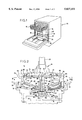
- FIG. 1 is a perspective view of a dishwasher using the soil separating system of the present invention
- FIG. 2 is a longitudinal sectional view of the soil separator mechanism of FIG. 1;
- FIG. 3 is a sectional view taken generally along line III--III of FIG. 2;
- FIG. 4 is a longitudinal sectional view of an alternate embodiment of the separator of FIG. 2;
- FIG. 5 is a perspective view of the sizing mechanism shown in FIG. 4.
- FIG. 6 is an exploded perspective view of the mechanism of FIG. 5.
- FIG. 1 illustrates a dishwasher 10 having a dish compartment 14 and holding racks 16 for holding dishes, as is known.
- a rotary water delivery mechanism 18 including water wash arms 20.
- the delivery mechanism 18 is mounted on top of a soil separator 24 via a water conduit 26 which feeds water to the delivery mechanism 18 (shown in FIG. 2).
- An upper wash arm can also be provided and flow connected to the separator 24 (not shown).
- FIG. 2 shows the soil separator 24 in more detail.
- the separator 24 is mounted on a floor 30 of the dish compartment 14.
- Soil laden water W proceeds through an annular gap 32 into the separator 24.
- a coarse screen 36 is provided in annular form around a center line of the separator 24. Water may proceed through the coarse screen 36 of a first flow rate and also proceed radially inwardly past the screen 36 to a central opening 38 to be drawn into the centrifuge 40 at a second flow rate. Soil laden water W passing through the screen 36 is pumped by centrifugal impeller 42 upwardly as shown.
- the impeller 42 is mounted to an inclined annular wall 46 partially defining the centrifuge 40.
- Inclined annular wall 46 continues to an annular vertical wall 50 which is closed by a disk shaped top wall 52.
- the disk shaped top wall 52 provides a central hub 54 which is connected by a shaft 56 and screw or bolt 57 to a motor shaft 58 driven by a motor 60.
- a seal 62 is provided to prevent water within the separator 24 from dripping down onto, for example, the motor or paneling beneath the dishwasher compartment 14.
- a sizing rotor 64 and/or chopping blade 101 is provided attached to the shaft 56 for rotation therewith.
- the sizing rotor 64 provides cutting or grating elements 65 which as rotated, grind food particles against stationary vanes 66.
- the chopping blade 101 provides high velocity impacts on soil to reduce particle size. Reduced size particles from either device proceed out of the drain 92, if operated in a "drain” mode, or allowed to remain in areas 100 and 102 if operated in a "wash” mode, until the system is drained.
- a water distribution diffuser 70 is provided above the hole 68.
- a passage 72 defined by the top wall 52 and diffuser 70 allows the water to join with the water moved upwardly by the centrifugal impeller 42 and proceed into a plenum 74 flow connected to the pipe 26 for distribution to the water distribution mechanism 18 for spraying the dishes.
- the mechanism 18 in all other respects is similar to known dishwasher wash arms. Additionally, if a top mounted upper washer arm is used, a conduit can be employed to flow connect the plenum 74 to a hose leading to the upper wash arm (not shown).
- annular soil concentration wall 78 can be provided surrounding the vertical annular wall 50. Water moved by the centrifugal impeller 42 and influenced by the spinning vertical annular wall 50 allows entrained soil to pass through an annular gap 80 into an annular sump 82 defined between the wall 78 and an outer wall 86 of the mechanism 24. A sump drain line 90 is provided leading from the sump 82 down to the area of the opening 38. Soil accumulated in the sump 82 can be therefore transported down to the separator entrance 38 for collection and confinement.
- the centrifugal impeller 42 pumps water through an annular vertical channel 43 upward to supply the pipe 26 with wash water.
- the centrifuge 40 is shown with radially aligned paddles 98 extending from the hub 54 for imparting rotational force to the column of water held within centrifuge 40.
- the holes 68 are shown which allow the central portion of the water within the centrifuge 40 to leave the centrifuge to pass through the pipe 26 to the recirculated into the dish compartment 14.
- the size and radial location of the holes 68 can be controlled to further screen soil particles.
- the centrifuge 40 functions on the principle that a spinning column of water with different diameters at each end will pump water.
- the centrifuge 40 has a smaller diameter at its entrance 38, and a slightly larger diameter defining the location of holes 68.
- the connector shaft 56 spins which spins the hub 54.
- the hub 54 spins the centrifuge walls 52, 50, 46 and the paddles 98 to spin water held within the centrifuge 40. Centrifugal forces separate food soils based on their densities within the centrifuge 40. Heavier than water soils collect on the outer wall of the centrifuge and lighter than water soils collect in the center.
- the centrifuge 40 is stopped. Some of the heavy food soils may fall out of the centrifuge 40 at this time.
- the drain system By activating the drain system and either allowing the centrifuge 40 to remain stationary, agitate by repeated direction changes, or rotate continuously in either direction, the water and soil will be pumped out of the dishwasher. Whether or not the centrifuge 40 is rotating or in which direction is dependent on the configuration of the soil sizing mechanisms and the type of food soils expected to be handled. In the case of a rotating centrifuge, some food particles and water will remain within the centrifuge after the unit has been pumped dry. At this point in operation, the centrifuge 40 is again stopped and the remaining water and soil should flow downwardly out of the centrifuge down to the sizing and drain area 100. The drain system is again activated to complete the system draining.
- the centrifuge 40 is designed to pump water out of the holes 68 at a relatively low flow rate.
- the centrifugal impeller 42 on the other hand serves to provide a main pumping action for the dishwasher.
- the impeller 42 draws water across the screen 36 for coarse screening.
- FIG. 4 describes an alternate embodiment separator 124 having a different soil sizing and drain area 130 including an alternate soil sizing rotor 164.
- This rotor 164 is shown in detail in FIGS. 5 and 6.
- the rotor 164 includes a propeller 166 which when spun in a draining direction encourages flow through the rotor 164 and when spun in a reverse direction (wash direction) prevents flow through the rotor 164.
- a perforated cylinder 168 is fastened to the propeller 166.
- the cylinder 168 allows water to pass through to drain during a drain cycle.
- the cylinder will also chop and size food particles.
- a spring finger element 170 passes an inside of the cylinder 168 to assist in forcing food particles against the cylinder inside surface to effectively grate or grind the particles.
- the finger elements 170 can be designed to deflect or rotate to prevent stalling the motor if a large hard particle wedges between the finger and the cylinder 168.
Landscapes
- Chemical & Material Sciences (AREA)
- Organic Chemistry (AREA)
- Chemical Kinetics & Catalysis (AREA)
- Engineering & Computer Science (AREA)
- Materials Engineering (AREA)
- Water Supply & Treatment (AREA)
- Inorganic Chemistry (AREA)
- Centrifugal Separators (AREA)
- Catalysts (AREA)
- Organic Low-Molecular-Weight Compounds And Preparation Thereof (AREA)
Abstract
A centrifugal soil separator for a dishwasher having a rotating centrifuge connected for rotation with a centrifugal impeller, the centrifugal impeller providing a majority of recirculating wash water for the dishwasher while the centrifuge accepts a second portion of flow and spins that portion of flow for soil separation and to achieve a pumping action to move that quantity of water to the wash water delivery system with the quantity of water moved by the centrifugal impeller. By a coordinated stopping, reversing and starting action of the centrifuge, soil collected therein can be disposed to a soil sizing and drain apparatus for flushing and draining the centrifuge.
Description
This is a division of application Ser. No. 08/713,488, filed Sep. 13, 1996, now allowed, U.S. Pat. No. 5,770,058, and claims the benefit of U.S. Provisional Application No.: 60/005,365 filed Oct. 17, 1995.
The invention relates to dishwashers, in particular to food soil separation and disposal mechanisms.
Many commercially available dishwashers utilize centrifugal forces generated by the dishwasher pump to provide for soil separation, and further rely on settling chambers or filters to contain the soils. U.S. Pat. No. 5,165,433 for example discloses such a system.
In that patent, an accumulator annular wall is provided around an annular pump chamber wall. Water is permitted to flow over the pump chamber wall into an annular slot area defined between the walls. An orifice through the accumulator wall allows water and soil to exit this annular slot area into an accumulator or settling area. A screen covering that area allows water to exit upwardly into the dishwasher area while soil is retained in the sump area to be disposed at timed intervals.
Such systems have the drawbacks of keeping filters free flowing or preventing disturbances in settling areas. To solve those problems, typically extra water is required in the form of back flush nozzles or large volume settling tanks. It is advantageous however to reduce water consumption and thereby conserve energy.
It is an object of the present invention to reduce energy and water consumption or storage in a dishwasher soil separation and disposal system. It is an object of the present invention to provide a soil separation system which does not require fine filtering elements or large settling tanks. It is an object of the present invention to provide a soil separation and disposal system which prevents accumulation of particles on dishes during a wash cycle. It is an object to provide a system which does not require water flow to back flush filters or screens.
The objects of the invention are achieved in that a centrifugal separator is provided which separates and contains soil particles without the need for a settling tank or fine filtering screens. The system also provides soil "sizing" (grinding or size reduction) and a drain system. A pump housing provides a coarse particle screen, flow gathering and redirection channels and additional soil separation means.
The centrifugal separator functions on the principle that a spinning column of water with different diameters at each end will pump water axially. Such a spinning column will also be acted upon by centrifugal forces. As soiled water is pumped through the separator, the centrifugal forces separate food soils based on their densities. Heavier than water soils collect on the outer wall and lighter than water soils collect in the center. By properly controlling the exit, "clean" water can be allowed to escape leaving the soils trapped.
To dispose trapped soils, the spinning column of water is stopped. Some of the "heavy" food soils are allowed to fall out of the column at this time. By reversing the spinning direction and activating the drain system, the water will be pumped out of the dishwasher. Due to the shape of the centrifuge, a significant amount of water and possible food soils are still contained and suspended in the separator after the unit has been pumped dry. By again stopping the motor, the remaining water and soils will fall out of the system below the inlet of the separator. At this point, the pump is again spun in the drain direction to complete the system draining.
Alternatively, disposing of water and food soils may be achieved by either stopping or agitating the separator while allowing a second, smaller pump to draw the soil and water from the unit.
Stopping and starting the system presents a disadvantage in that the system attempts to pump at a high rate during start up. With a large exit opening, this high rate can empty much of the soil that was trapped and dispose it on the dish load or plug spray arm nozzles. To correct this problem, a ring of holes on the centrifuge exit are used in place of an open hole or band. By controlling the number and size of the holes, both the flow rate and soil particle size can be regulated during start-up and normal operation.
Attached to the separator is a centrifugal impeller. Because the separator is designed to pump at a relatively low flow rate, a centrifugal impeller serves to provide the main pumping action for the dishwasher. The impeller draws its water through a coarse mesh screen which prevents large food soils from plugging the water delivery system. This coarse mesh may be configured in many different ways to allow either automatic or manual cleaning.
The impeller can also aid soil separation by adding a soil concentration wall similar to that used in U.S. Pat. 5,165,433. This wall allows soil concentrations to be increased and fed to the separator for containment and eventual disposal.
Both the water from the impeller and the separator converge at the outer upper edge of the separator. Here, the spinning water is gathered and redirected by a diffuser to supply the water feed system to the water delivery arms within the dish compartment.
FIG. 1 is a perspective view of a dishwasher using the soil separating system of the present invention;
FIG. 2 is a longitudinal sectional view of the soil separator mechanism of FIG. 1;
FIG. 3 is a sectional view taken generally along line III--III of FIG. 2;
FIG. 4 is a longitudinal sectional view of an alternate embodiment of the separator of FIG. 2;
FIG. 5 is a perspective view of the sizing mechanism shown in FIG. 4; and
FIG. 6 is an exploded perspective view of the mechanism of FIG. 5.
FIG. 1 illustrates a dishwasher 10 having a dish compartment 14 and holding racks 16 for holding dishes, as is known. At a bottom of the dish compartment 14 is a rotary water delivery mechanism 18 including water wash arms 20. The delivery mechanism 18 is mounted on top of a soil separator 24 via a water conduit 26 which feeds water to the delivery mechanism 18 (shown in FIG. 2). An upper wash arm can also be provided and flow connected to the separator 24 (not shown).
FIG. 2 shows the soil separator 24 in more detail. The separator 24 is mounted on a floor 30 of the dish compartment 14. Soil laden water W proceeds through an annular gap 32 into the separator 24. A coarse screen 36 is provided in annular form around a center line of the separator 24. Water may proceed through the coarse screen 36 of a first flow rate and also proceed radially inwardly past the screen 36 to a central opening 38 to be drawn into the centrifuge 40 at a second flow rate. Soil laden water W passing through the screen 36 is pumped by centrifugal impeller 42 upwardly as shown.
The impeller 42 is mounted to an inclined annular wall 46 partially defining the centrifuge 40. Inclined annular wall 46 continues to an annular vertical wall 50 which is closed by a disk shaped top wall 52. The disk shaped top wall 52 provides a central hub 54 which is connected by a shaft 56 and screw or bolt 57 to a motor shaft 58 driven by a motor 60. A seal 62 is provided to prevent water within the separator 24 from dripping down onto, for example, the motor or paneling beneath the dishwasher compartment 14. A sizing rotor 64 and/or chopping blade 101 is provided attached to the shaft 56 for rotation therewith. The sizing rotor 64 provides cutting or grating elements 65 which as rotated, grind food particles against stationary vanes 66. The chopping blade 101 provides high velocity impacts on soil to reduce particle size. Reduced size particles from either device proceed out of the drain 92, if operated in a "drain" mode, or allowed to remain in areas 100 and 102 if operated in a "wash" mode, until the system is drained.
Through the disk shaped top wall 52 are arranged a plurality of holes 68 shown coined downwardly which allow water spun within the centrifuge 40 to pass upwardly out of the centrifuge 40. A water distribution diffuser 70 is provided above the hole 68. A passage 72 defined by the top wall 52 and diffuser 70 allows the water to join with the water moved upwardly by the centrifugal impeller 42 and proceed into a plenum 74 flow connected to the pipe 26 for distribution to the water distribution mechanism 18 for spraying the dishes.
The mechanism 18 in all other respects is similar to known dishwasher wash arms. Additionally, if a top mounted upper washer arm is used, a conduit can be employed to flow connect the plenum 74 to a hose leading to the upper wash arm (not shown).
Also, an annular soil concentration wall 78 can be provided surrounding the vertical annular wall 50. Water moved by the centrifugal impeller 42 and influenced by the spinning vertical annular wall 50 allows entrained soil to pass through an annular gap 80 into an annular sump 82 defined between the wall 78 and an outer wall 86 of the mechanism 24. A sump drain line 90 is provided leading from the sump 82 down to the area of the opening 38. Soil accumulated in the sump 82 can be therefore transported down to the separator entrance 38 for collection and confinement.
The centrifugal impeller 42 pumps water through an annular vertical channel 43 upward to supply the pipe 26 with wash water.
As shown in FIG. 3, the centrifuge 40 is shown with radially aligned paddles 98 extending from the hub 54 for imparting rotational force to the column of water held within centrifuge 40. The holes 68 are shown which allow the central portion of the water within the centrifuge 40 to leave the centrifuge to pass through the pipe 26 to the recirculated into the dish compartment 14. The size and radial location of the holes 68 can be controlled to further screen soil particles.
In operation, the centrifuge 40 functions on the principle that a spinning column of water with different diameters at each end will pump water. The centrifuge 40 has a smaller diameter at its entrance 38, and a slightly larger diameter defining the location of holes 68. Thus when the motor shaft 58 spins, the connector shaft 56 spins which spins the hub 54. The hub 54 spins the centrifuge walls 52, 50, 46 and the paddles 98 to spin water held within the centrifuge 40. Centrifugal forces separate food soils based on their densities within the centrifuge 40. Heavier than water soils collect on the outer wall of the centrifuge and lighter than water soils collect in the center. By locating the holes 68 at a preselected radial distance from a center line CL of the centrifuge at least equal to radial location of inlet wall 38 to the same centerline CL, relatively clean water can be dispensed out of the holes 68.
To dispose the trapped soils, periodically, the centrifuge 40 is stopped. Some of the heavy food soils may fall out of the centrifuge 40 at this time. By activating the drain system and either allowing the centrifuge 40 to remain stationary, agitate by repeated direction changes, or rotate continuously in either direction, the water and soil will be pumped out of the dishwasher. Whether or not the centrifuge 40 is rotating or in which direction is dependent on the configuration of the soil sizing mechanisms and the type of food soils expected to be handled. In the case of a rotating centrifuge, some food particles and water will remain within the centrifuge after the unit has been pumped dry. At this point in operation, the centrifuge 40 is again stopped and the remaining water and soil should flow downwardly out of the centrifuge down to the sizing and drain area 100. The drain system is again activated to complete the system draining.
The centrifuge 40 is designed to pump water out of the holes 68 at a relatively low flow rate. The centrifugal impeller 42 on the other hand serves to provide a main pumping action for the dishwasher. The impeller 42 draws water across the screen 36 for coarse screening.
FIG. 4 describes an alternate embodiment separator 124 having a different soil sizing and drain area 130 including an alternate soil sizing rotor 164. This rotor 164 is shown in detail in FIGS. 5 and 6.
The rotor 164 includes a propeller 166 which when spun in a draining direction encourages flow through the rotor 164 and when spun in a reverse direction (wash direction) prevents flow through the rotor 164. A perforated cylinder 168 is fastened to the propeller 166. The cylinder 168 allows water to pass through to drain during a drain cycle. The cylinder will also chop and size food particles. A spring finger element 170 passes an inside of the cylinder 168 to assist in forcing food particles against the cylinder inside surface to effectively grate or grind the particles. The finger elements 170 can be designed to deflect or rotate to prevent stalling the motor if a large hard particle wedges between the finger and the cylinder 168.
Although the present invention has been described with reference to a specific embodiment, those of skill in the art will recognize that changes may be made thereto without departing from the scope and spirit of the invention as set forth in the appended claims.
Claims (12)
1. A method for separating soil from soil laden water for a recirculating wash water dishwasher; comprising the steps of:
providing a soil separator including a centrifuge;
receiving wash water from a dish compartment of said dishwasher into said soil separator;
in said soil separator receiving a first flow of said wash water into said centrifuge;
spinning said centrifuge with a motor to maintain a spinning column of water having a vertically upwardly increasing diameter;
pumping water through said centrifuge by said spinning of said centrifuge to an exit located at a top region of said centrifuge;
reapplying water exiting said centrifuge to said dish compartment; and
draining at least some of the soil from the soil separator.
2. The method according to claim 1 comprising the further steps of:
receiving a second flow of said wash water and passing said second flow through a coarse screening, and
pumping said second flow to combine with said first flow delivered by said centrifuge and passing both said first and second flows to said dish compartment.
3. The method according to claim 2 further comprising the step of flowing at least some of the second flow of the wash water into said soil separator after the step of passing said second flow through the course screening.
4. The method according to claim 1 comprising the further step of periodically stopping said centrifuge to allow soil and water to flow by gravity downwardly to be drained from the separator; and
restarting the centrifuge in a reverse direction from a first direction in said spinning said centrifuge step to assist in draining of said centrifuge of soil water.
5. The method according to claim 4 comprising the further steps of after restarting said centrifuge in the reverse direction, stopping said centrifuge to allow soil and water to flow by gravity downwardly to be drained; and
restarting the centrifuge again in the reverse direction to drain said water from said centrifuge.
6. The method according to claim 4 comprising the further step of, while draining, sizing said soil to be drain with a rotating sizing mechanism.
7. The method according to claim 1 wherein the step of spinning said centrifuge further comprises the step of separating soil heavier than water and soil lighter than water in said wash water into separate areas in the spinning column of water.
8. The method according to claim 1 wherein the step of pumping water through said centrifuge further comprises the step of pumping water from generally a mid-area of the spinning column of water between radially innermost and outermost areas of the spinning column of water.
9. The method according to claim 1 wherein the step of draining at least some of the soil from the soil separator comprises a step selected from the group consisting of stopping the spinning of the centrifuge, repeatedly changing a direction of spin of the centrifuge, continuing to spin the centrifuge, reversing a direction of spin of the centrifuge, and combinations thereof.
10. A method of washing soiled dishes in a dishwasher comprising the steps of:
applying water to the soiled dishes;
removing at least some soil from the dishes with the water to form soiled water;
rotating the soiled water in a column having different diameters at opposite ends of the column;
moving at least some of the soil in the rotating column of soiled water to form column areas having a relatively high concentration of soil and a relatively low concentration of soil;
screening soil from a portion of the soiled water to form screened soiled water; and
combining the screened soiled water with the water from the column area having a relatively low concentration of soil to form soil reduced water; and
wherein the step of applying water to the soiled dishes comprises the step of applying the soil reduced water to the dishes.
11. A method of recirculating water in a dishwasher comprising the steps of:
distributing the water in a dish compartment of the dishwasher;
flowing the water from the dish compartment to a soil separator;
spinning the soil separator by driving the soil separator with a motor;
spinning the water in the soil separator to form a column of water having different diameters at opposite ends of the column of water; and
flowing the water from the column of water to the dish compartment.
12. The method of claim 11 further comprising the steps of:
bypassing a portion of the water from the dish compartment around the spinning column of water; and
flowing the portion of water bypassing the spinning column of water to the dish compartment.
Priority Applications (1)
| Application Number | Priority Date | Filing Date | Title |
|---|---|---|---|
| US08/848,615 US5837151A (en) | 1995-09-29 | 1997-04-29 | Methods for separating soil from soil laden water in dishwashers |
Applications Claiming Priority (3)
| Application Number | Priority Date | Filing Date | Title |
|---|---|---|---|
| US536595P | 1995-09-29 | 1995-09-29 | |
| US08/713,488 US5770058A (en) | 1995-09-29 | 1996-09-13 | Centrifugal separator |
| US08/848,615 US5837151A (en) | 1995-09-29 | 1997-04-29 | Methods for separating soil from soil laden water in dishwashers |
Related Parent Applications (1)
| Application Number | Title | Priority Date | Filing Date |
|---|---|---|---|
| US08/713,488 Division US5770058A (en) | 1995-09-29 | 1996-09-13 | Centrifugal separator |
Publications (1)
| Publication Number | Publication Date |
|---|---|
| US5837151A true US5837151A (en) | 1998-11-17 |
Family
ID=21715487
Family Applications (2)
| Application Number | Title | Priority Date | Filing Date |
|---|---|---|---|
| US08/713,488 Expired - Lifetime US5770058A (en) | 1995-09-29 | 1996-09-13 | Centrifugal separator |
| US08/848,615 Expired - Fee Related US5837151A (en) | 1995-09-29 | 1997-04-29 | Methods for separating soil from soil laden water in dishwashers |
Family Applications Before (1)
| Application Number | Title | Priority Date | Filing Date |
|---|---|---|---|
| US08/713,488 Expired - Lifetime US5770058A (en) | 1995-09-29 | 1996-09-13 | Centrifugal separator |
Country Status (2)
| Country | Link |
|---|---|
| US (2) | US5770058A (en) |
| DE (1) | DE19639932A1 (en) |
Cited By (8)
| Publication number | Priority date | Publication date | Assignee | Title |
|---|---|---|---|---|
| DE19836739A1 (en) * | 1998-08-13 | 2000-02-17 | Meiko Maschinenbau Gmbh & Co | dishwasher |
| US20040045586A1 (en) * | 2002-09-06 | 2004-03-11 | Rappette Antony Mark | Stop start wash cycle for dishwashers |
| US20060174925A1 (en) * | 2005-02-09 | 2006-08-10 | Maytag Corp. | Dishwasher drain pump assembly |
| US20080011335A1 (en) * | 2006-07-12 | 2008-01-17 | Samsung Electronics Co. Ltd. | Dish washing machine |
| WO2016130027A1 (en) * | 2015-02-13 | 2016-08-18 | Fisher & Paykel Appliances Limited | Wash system for washing appliance |
| US10287192B2 (en) | 2011-03-17 | 2019-05-14 | Ecolab Usa Inc. | Composition and method for continuous or intermittent removal of soil from recirculated washing solution |
| US11039728B2 (en) | 2017-02-28 | 2021-06-22 | Whirlpool Corporation | Washing appliance having a recirculation circuit |
| US11478121B1 (en) | 2021-06-29 | 2022-10-25 | Midea Group Co., Ltd. | Filtration assembly with grinding mechanism |
Families Citing this family (12)
| Publication number | Priority date | Publication date | Assignee | Title |
|---|---|---|---|---|
| US5937880A (en) * | 1997-10-03 | 1999-08-17 | Tca, Inc. | Under counter dish washing machine |
| KR200328651Y1 (en) * | 2002-12-07 | 2003-10-01 | 윤장식 | centurifugal type air purification apparatus |
| KR101052974B1 (en) * | 2004-04-22 | 2011-07-29 | 엘지전자 주식회사 | Air brake structure of dishwasher |
| US8741433B2 (en) * | 2004-12-10 | 2014-06-03 | Curwood, Inc. | Packaging films comprising nylon blend compositions |
| DE102004060950A1 (en) | 2004-12-17 | 2006-06-29 | BSH Bosch und Siemens Hausgeräte GmbH | Dishwasher with low-maintenance sieve system |
| US7670439B2 (en) * | 2006-03-31 | 2010-03-02 | Maytag Corporation | Chopping system for a dishwasher pump assembly |
| US8876980B2 (en) | 2010-06-30 | 2014-11-04 | Electrolux Home Products, Inc. | System and associated method for preventing overfilling in a dishwasher |
| US8702874B2 (en) | 2011-02-08 | 2014-04-22 | Electrolux Home Products, Inc. | Method and system for removing a clog from a dishwasher |
| US9770156B2 (en) * | 2015-08-10 | 2017-09-26 | Haier Us Appliance Solutions, Inc. | Macerator assembly for appliances |
| CN106308715A (en) * | 2016-08-20 | 2017-01-11 | 刘擂 | Cleaning device for second-hand kitchenware |
| BR112019016905A2 (en) | 2017-02-24 | 2020-04-14 | Electrolux Appliances AB | method for addressing a clogged condition in a dishwasher, dishwasher and control system |
| AU2018390481A1 (en) * | 2017-12-19 | 2020-07-09 | Xeros Limited | Filter for a treatment apparatus |
Citations (22)
| Publication number | Priority date | Publication date | Assignee | Title |
|---|---|---|---|---|
| US1583236A (en) * | 1919-12-20 | 1926-05-04 | William U Murrish | Dishwashing machine |
| US3322285A (en) * | 1965-01-05 | 1967-05-30 | Whirlpool Co | Filter for washing apparatus |
| US3575185A (en) * | 1968-10-23 | 1971-04-20 | Gen Motors Corp | Self-cleaning dishwasher strainer |
| US3669132A (en) * | 1970-09-29 | 1972-06-13 | Wesley Mamrose | Dishwashing apparatus |
| GB1352655A (en) * | 1971-08-04 | 1974-05-08 | Sundstrand Corp | Centrifugal pump having a contamination separator |
| US3989054A (en) * | 1975-10-28 | 1976-11-02 | General Motors Corporation | Dishwasher system |
| US4038103A (en) * | 1976-07-27 | 1977-07-26 | Hobart Corporation | Dishwasher filter flushing system |
| US4039452A (en) * | 1976-11-15 | 1977-08-02 | Fernandez John J | Self-cleaning filter |
| US4150679A (en) * | 1977-11-23 | 1979-04-24 | General Electric Company | Dishwasher with improved bypass filter arrangement |
| US4297210A (en) * | 1980-07-31 | 1981-10-27 | Fives-Cail Babcock | Centrifugal separator |
| US4319599A (en) * | 1980-09-22 | 1982-03-16 | Whirlpool Corporation | Vertical soil separator for dishwasher |
| US4346723A (en) * | 1981-03-25 | 1982-08-31 | Hobart Corporation | Apparatus for a warewasher bypass soil collector |
| US4347861A (en) * | 1981-02-25 | 1982-09-07 | Whirlpool Corporation | Dishwasher soil separator |
| US4392891A (en) * | 1980-07-02 | 1983-07-12 | Hobart Corporation | Dishwasher soil collecting circuit |
| US4559959A (en) * | 1982-10-18 | 1985-12-24 | Hobart Corporation | Dishwashing apparatus |
| US4673441A (en) * | 1982-10-18 | 1987-06-16 | Meyers Theodore F | Dishwashing method |
| US4971518A (en) * | 1988-04-30 | 1990-11-20 | Asea Brown Boveri Ltd. | Radial fan with integrated dust separator |
| US4972861A (en) * | 1988-11-23 | 1990-11-27 | Industrie Zanussi S.P.A. | Washing machine including improved apparatus for cleaning a recirculating filter thereof |
| US5097855A (en) * | 1987-11-26 | 1992-03-24 | Abb Cylinda Ab | Method for self-cleaning of a strainer system in a dishwasher and a dish-washer having means for carrying out the method |
| US5165433A (en) * | 1991-08-19 | 1992-11-24 | Whirlpool Corporation | Soil separator for a domestic dishwasher |
| US5333631A (en) * | 1993-05-04 | 1994-08-02 | White Consolidated Industries, Inc. | Cleaning wash-arm for dishwashing filter |
| US5345957A (en) * | 1993-09-07 | 1994-09-13 | Maytag Corporation | Dishwasher filter arrangement |
-
1996
- 1996-09-13 US US08/713,488 patent/US5770058A/en not_active Expired - Lifetime
- 1996-09-27 DE DE19639932A patent/DE19639932A1/en not_active Withdrawn
-
1997
- 1997-04-29 US US08/848,615 patent/US5837151A/en not_active Expired - Fee Related
Patent Citations (22)
| Publication number | Priority date | Publication date | Assignee | Title |
|---|---|---|---|---|
| US1583236A (en) * | 1919-12-20 | 1926-05-04 | William U Murrish | Dishwashing machine |
| US3322285A (en) * | 1965-01-05 | 1967-05-30 | Whirlpool Co | Filter for washing apparatus |
| US3575185A (en) * | 1968-10-23 | 1971-04-20 | Gen Motors Corp | Self-cleaning dishwasher strainer |
| US3669132A (en) * | 1970-09-29 | 1972-06-13 | Wesley Mamrose | Dishwashing apparatus |
| GB1352655A (en) * | 1971-08-04 | 1974-05-08 | Sundstrand Corp | Centrifugal pump having a contamination separator |
| US3989054A (en) * | 1975-10-28 | 1976-11-02 | General Motors Corporation | Dishwasher system |
| US4038103A (en) * | 1976-07-27 | 1977-07-26 | Hobart Corporation | Dishwasher filter flushing system |
| US4039452A (en) * | 1976-11-15 | 1977-08-02 | Fernandez John J | Self-cleaning filter |
| US4150679A (en) * | 1977-11-23 | 1979-04-24 | General Electric Company | Dishwasher with improved bypass filter arrangement |
| US4392891A (en) * | 1980-07-02 | 1983-07-12 | Hobart Corporation | Dishwasher soil collecting circuit |
| US4297210A (en) * | 1980-07-31 | 1981-10-27 | Fives-Cail Babcock | Centrifugal separator |
| US4319599A (en) * | 1980-09-22 | 1982-03-16 | Whirlpool Corporation | Vertical soil separator for dishwasher |
| US4347861A (en) * | 1981-02-25 | 1982-09-07 | Whirlpool Corporation | Dishwasher soil separator |
| US4346723A (en) * | 1981-03-25 | 1982-08-31 | Hobart Corporation | Apparatus for a warewasher bypass soil collector |
| US4559959A (en) * | 1982-10-18 | 1985-12-24 | Hobart Corporation | Dishwashing apparatus |
| US4673441A (en) * | 1982-10-18 | 1987-06-16 | Meyers Theodore F | Dishwashing method |
| US5097855A (en) * | 1987-11-26 | 1992-03-24 | Abb Cylinda Ab | Method for self-cleaning of a strainer system in a dishwasher and a dish-washer having means for carrying out the method |
| US4971518A (en) * | 1988-04-30 | 1990-11-20 | Asea Brown Boveri Ltd. | Radial fan with integrated dust separator |
| US4972861A (en) * | 1988-11-23 | 1990-11-27 | Industrie Zanussi S.P.A. | Washing machine including improved apparatus for cleaning a recirculating filter thereof |
| US5165433A (en) * | 1991-08-19 | 1992-11-24 | Whirlpool Corporation | Soil separator for a domestic dishwasher |
| US5333631A (en) * | 1993-05-04 | 1994-08-02 | White Consolidated Industries, Inc. | Cleaning wash-arm for dishwashing filter |
| US5345957A (en) * | 1993-09-07 | 1994-09-13 | Maytag Corporation | Dishwasher filter arrangement |
Cited By (17)
| Publication number | Priority date | Publication date | Assignee | Title |
|---|---|---|---|---|
| DE19836739A1 (en) * | 1998-08-13 | 2000-02-17 | Meiko Maschinenbau Gmbh & Co | dishwasher |
| US20040045586A1 (en) * | 2002-09-06 | 2004-03-11 | Rappette Antony Mark | Stop start wash cycle for dishwashers |
| US7232494B2 (en) | 2002-09-06 | 2007-06-19 | Whirlpool Corporation | Stop start wash cycle for dishwashers |
| US20060174925A1 (en) * | 2005-02-09 | 2006-08-10 | Maytag Corp. | Dishwasher drain pump assembly |
| US7472714B2 (en) | 2005-02-09 | 2009-01-06 | Maytag Corporation | Dishwasher drain pump assembly |
| US20080011335A1 (en) * | 2006-07-12 | 2008-01-17 | Samsung Electronics Co. Ltd. | Dish washing machine |
| US7946304B2 (en) * | 2006-07-12 | 2011-05-24 | Samsung Electronics Co., Ltd. | Dish washing machine having sump with drainage channel to remove wash water |
| US20110186095A1 (en) * | 2006-07-12 | 2011-08-04 | Samsung Electronics Co., Ltd. | Dish washing machine |
| US10676380B2 (en) | 2011-03-17 | 2020-06-09 | Ecolab Usa Inc. | Composition and method for continuous or intermittent removal of soil from recirculated washing solution |
| US10287192B2 (en) | 2011-03-17 | 2019-05-14 | Ecolab Usa Inc. | Composition and method for continuous or intermittent removal of soil from recirculated washing solution |
| WO2016130027A1 (en) * | 2015-02-13 | 2016-08-18 | Fisher & Paykel Appliances Limited | Wash system for washing appliance |
| US11000177B2 (en) | 2015-02-13 | 2021-05-11 | Fisher & Paykel Appliances Limited | Wash system for washing appliance |
| US11672403B2 (en) | 2015-02-13 | 2023-06-13 | Fisher & Paykel Appliances Limited | Wash system for washing appliance |
| US11039728B2 (en) | 2017-02-28 | 2021-06-22 | Whirlpool Corporation | Washing appliance having a recirculation circuit |
| US11739471B2 (en) | 2017-02-28 | 2023-08-29 | Whirlpool Corporation | Washing appliance having a recirculation circuit |
| US11478121B1 (en) | 2021-06-29 | 2022-10-25 | Midea Group Co., Ltd. | Filtration assembly with grinding mechanism |
| US11903544B2 (en) | 2021-06-29 | 2024-02-20 | Midea Group Co., Ltd. | Filtration assembly with grinding mechanism |
Also Published As
| Publication number | Publication date |
|---|---|
| DE19639932A1 (en) | 1997-04-03 |
| US5770058A (en) | 1998-06-23 |
Similar Documents
| Publication | Publication Date | Title |
|---|---|---|
| US5837151A (en) | Methods for separating soil from soil laden water in dishwashers | |
| CA2183285C (en) | Soil separation channel for dishwasher pump system | |
| US5779812A (en) | Multi-mesh mechanical filter screen system for dishwashers | |
| US5711326A (en) | Dishwasher accumulator soil removal grating for a filter system | |
| US6418943B1 (en) | Wash liquid circulation system for a dishwasher | |
| CA1071507A (en) | Dishwasher filter flushing system | |
| US4150680A (en) | Dishwasher soil separator | |
| CA2075251C (en) | Soil separator for a domestic dishwasher | |
| US6182674B1 (en) | Pump and soil collection system for a dishwasher | |
| CN1176632C (en) | Water filter for dish-washing machine | |
| US4347861A (en) | Dishwasher soil separator | |
| US4168715A (en) | Dishwasher soil separator | |
| US5909743A (en) | Automatic purge filtration system for a dishwasher | |
| US6782899B2 (en) | Dishwasher | |
| US5762080A (en) | Dishwasher cycle pulsing pump out of collection chamber | |
| US5700329A (en) | Filter standpipe for dishwasher | |
| US5165435A (en) | Wash arm assembly for a domestic dishwasher | |
| US5628334A (en) | Dishwasher with food particle macerator and mincer | |
| US4066552A (en) | Combined pump and self-cleaning centrifugal contamination separator | |
| US6494929B2 (en) | Cyclone for suction cleaner | |
| US5582742A (en) | Rotary distribution pipe assembly | |
| US4184951A (en) | Method and apparatus for cleaning liquids | |
| AU2004280107B2 (en) | Grit trap | |
| KR100471638B1 (en) | A vacuum dehydrating system for texture manufacturing | |
| KR100267930B1 (en) | Washing machine |
Legal Events
| Date | Code | Title | Description |
|---|---|---|---|
| FPAY | Fee payment |
Year of fee payment: 4 |
|
| REMI | Maintenance fee reminder mailed | ||
| LAPS | Lapse for failure to pay maintenance fees | ||
| STCH | Information on status: patent discontinuation |
Free format text: PATENT EXPIRED DUE TO NONPAYMENT OF MAINTENANCE FEES UNDER 37 CFR 1.362 |
|
| FP | Lapsed due to failure to pay maintenance fee |
Effective date: 20061117 |