US582012A - Bottle-washer - Google Patents
Bottle-washer Download PDFInfo
- Publication number
- US582012A US582012A US582012DA US582012A US 582012 A US582012 A US 582012A US 582012D A US582012D A US 582012DA US 582012 A US582012 A US 582012A
- Authority
- US
- United States
- Prior art keywords
- bottle
- carrier
- brush
- water
- nozzle
- Prior art date
- Legal status (The legal status is an assumption and is not a legal conclusion. Google has not performed a legal analysis and makes no representation as to the accuracy of the status listed.)
- Expired - Lifetime
Links
- XLYOFNOQVPJJNP-UHFFFAOYSA-N water Substances O XLYOFNOQVPJJNP-UHFFFAOYSA-N 0.000 description 14
- 230000006872 improvement Effects 0.000 description 8
- 230000033001 locomotion Effects 0.000 description 7
- 238000004140 cleaning Methods 0.000 description 4
- 230000009471 action Effects 0.000 description 2
- 238000005406 washing Methods 0.000 description 2
- 238000010276 construction Methods 0.000 description 1
- 238000006073 displacement reaction Methods 0.000 description 1
- 230000000694 effects Effects 0.000 description 1
- 230000007246 mechanism Effects 0.000 description 1
- 238000000034 method Methods 0.000 description 1
- 230000004048 modification Effects 0.000 description 1
- 238000012986 modification Methods 0.000 description 1
- 230000008569 process Effects 0.000 description 1
- 239000008237 rinsing water Substances 0.000 description 1
- 239000000126 substance Substances 0.000 description 1
Images


Classifications
-
- B—PERFORMING OPERATIONS; TRANSPORTING
- B08—CLEANING
- B08B—CLEANING IN GENERAL; PREVENTION OF FOULING IN GENERAL
- B08B9/00—Cleaning hollow articles by methods or apparatus specially adapted thereto
- B08B9/08—Cleaning containers, e.g. tanks
- B08B9/20—Cleaning containers, e.g. tanks by using apparatus into or on to which containers, e.g. bottles, jars, cans are brought
- B08B9/36—Cleaning containers, e.g. tanks by using apparatus into or on to which containers, e.g. bottles, jars, cans are brought the apparatus cleaning by using brushes
Definitions
- This invention relates to bottle-washing machines of the general character of that shown in Letters Patent of the United States granted to me March 3, 1806, No. 555,598, in which the bottles to be cleaned are suitably supported upon a traveling carrier, and being cleaned externally by suitable means are also cleansed internally during their travel by the introduction of a brush and a subsequent rinsing.
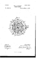
- Figure 1 is a vertical central section of the complete machine with some parts shown in elevation.
- Fig. 2 is a vertical central section of the complete machine with some parts shown in elevation.
- Fig. 5 is a detail view of one of the nozzles hereinafter referred to and its adjuncts.
- the supportirig-framework comprises a suitable base A, posts or standards A A an annular plate or table A and an interior standard or bracket A the said base A and the head a of the standard or bracket A affording bearings for a vertical shaft B.
- a drum 0 is secured to the shaftB to carry brushes for cleaning the outsides of the bottles, and a carrier I), which rotates upon the head of the bracket A, supports the bottles which are to be cleaned and carries them between the inner brushes K K and the outerbrushes K K, suitable means, as fully described in.
- said Letters Patent being provided to hold the bottles in position, preferably parallel with the axis of the carrier and with their mouths downward, during the process of cleaning.
- each bottle rests upon an annular socket E, which. permits a brush and also a stream of water to be introduced into the bottle throughit, all of said sockets E being supported by the carrier D.
- the clamping or holding devices are so arranged as to permit the introduction of a bottle to be cleaned as the holder is presented at the front of the machine and to permit it to be removed when the holder has completed or nearly completed its revolution with the carrier.
- For effecting the travel of the carrier D it is represented as provided with a bevel-rack D engaged by a bevelpinion b, which is carried by a counter-shaft B and is driven by gears 11 and b from the main driving-shaft B.
- Bevel-gears b and 19' secured, respectively, to the vertical shaft 13 and the driving-shaft B, provide for the rotation of the said shaft B and the brush-carrier C.
- each brush N is preferably carried bya stem or spindle n, which is mounted in a slide at, the latter being guided by and sliding upon rods 'n/ parallel with the axis of the carrier and fixed to a ring 0, supported from the carrier.
- Springs 02 draw each slide upward to cause the brush to enter the bottle in line with it, and each slide has a roller n which is adapted to travel in contact with a fixed cam-track 71 which permits the introduction of the brushes into the bottles and effects the withdrawal of the same at the proper time.
- each brush may be rotated while it is within the bottle and while it travels with the bottle-carrier, and also that it may cease to rotate when it is withdrawn from the bottle, I have provided the following devices:
- the lower end of the stem 01, which carries the brush N, is mounted in the slide at so that it will rotate freely therein and is held to move therewith.
- the said spindle n passes through a sleeve n supported in a bearing n secured to the fixed rods 'n' The aperture through the sleeve 01.
- the spindle n is preferably polygonal in cross-section, and the spindle n is correspondingly shaped in cross-section for the greater portion of its length, so that the spindle and sleeve shall be engaged to rotate together; but that portion of the spindle which is within the sleeve when the brush is fully withdrawn from the bottle is preferably cylindrical, so that the sleeve may then rotate independently of the spindle, and the brush may therefore cease to rotate when it is withdrawn from the bottle.
- each sleeve may be caused to rotate by a variety of driving devices, such as a band or a friction-gear, and as a convenient means of rotating them
- driving devices such as a band or a friction-gear
- the latter may be driven independently of the bottle carrier by any suitable means.
- each bottle is thoroughly brushed and scrubbed in the course of its travel from the point where it is inserted in the bottle-carrier to the point where it is removed therefrom. Furthermore, each brush ceases to rotate as soon as it is completely withdrawn from the bottle.
- any other suitable means for rotating the inside brushes may be employed.
- the shell n maybe formed as a drum, and a friction-wheel a may be fixed to the spindle n of the brush to move up and down therewith and always in contact with the drum, so that the brush is continuously driven.
- a friction-wheel a may be fixed to the spindle n of the brush to move up and down therewith and always in contact with the drum, so that the brush is continuously driven.
- each bottle shall be rinsed thoroughly after the withdrawal of the brush therefrom.
- this action was provided for by forming in each annular socket E a nozzle through which a stream of water might be directed into the bottle; but this nozzle caused the brushes to wear out rapidly and made it practically impossible to employ brushes of the kind which in other respects would give the best results.
- I have sought to overcome this difliculty and will proceed to describe the means which I have devised for the purpose, the main feature of such means being-a nozzle which is arranged to be moved toward the bottle-mouth to introduce a stream of water into the same and to be moved away therefrom, so as to permit the brush to beintroduced without interference.
- the bearing block or head a of the bracket A is represented as having an annular channel a formed therein, while the hub d of the carrier D has suitable packing-glands above and below the annular channel.
- a water-supply pipe M is connected to the bearing block or head a and is adapted to furnish thereto a continuous supply of water. From the hub d and in line with the annu- IIC larchannel a radiate a series of pipes m on, one for each pair of bottle-holders.
- each pipe m has at its outer end a transverse pipe or head m upon each end of which is mounted a hub m which carries the corresponding nozzle m so that the nozzles are free to swing.
- the ends of the pipes at are closed by suitable caps, and in each pipe, near the end thereof, is formed a port 072 which is adapted to register with the bore of the nozzle m when the latter is swung into position to direct a stream of water into the bottle and at all other times to be closed by the hub m this arrangement constituting a valve to control the delivery of the water.
- the nozzles are held normally away from the bottle-mouths by springs m which are connected to arms m projecting from the nozzles on.
- each nozzle preferably having a roller m rests against and rides upon a cam-track m which may be supported by a flange a secured to the standard or bracket A the said cam-track being so shaped as to swing the nozzle toward and against the socket E as soon as the brush N is drawn out of the way and to release the nozzle as soon as the bottle has been thoroughly rinsed.
Landscapes
- Engineering & Computer Science (AREA)
- Mechanical Engineering (AREA)
- Cleaning In General (AREA)
Description
( Model.) 4sheets-shee t 1.. M. E. DONALLY.
BOTTLE WASHER. No. 582,012. Pat'nt'ed May 41,1897.
.fl tiest: Inventor:
(N0 Model.) 4 Sheets-Sheet 2.
M. "E. DONALLY. BOTTLE WASHER.
No. 582,012. Patented Ma 4, 1897.
fl tziest Inventor-.-
(No Model.) 4 Sheqts-Sheet 3.
' M. B. DONALLY.
BOTTLE WASHER.
No. 582,012. Patented May 4, 1897.
(No Model.)
4 Sheets-Sheet 4.
M. E. DONALLY. BOTTLE WASHER.
Patented May 4, 1897.
m: Noam PETERS co. marauma. msumn'mu, n, c
FFIQETI MELVIN E. DO NALLY, OF BROOKLYN, NEW YORK.
BOTTLE-WASH ER.
SPECIFICATION forming part of Letters Patent No. 582,012, dated May 4, 1897. Application filed November 17, 1896. Serial No. 612,425. (No model.)
To to whom it may concern:
Be it known that I, MELVIN E. 'DoNALLY, a citizen of the Dominion of Canada, residing in the city of Brooklyn, in the county of Kings and State of New York, have invented certain new and useful'Im provements in Bottle-Washing Machines, of which the following is a specification, reference being had to the accompanying drawings, forming a part hereof.
This invention relates to bottle-washing machines of the general character of that shown in Letters Patent of the United States granted to me March 3, 1806, No. 555,598, in which the bottles to be cleaned are suitably supported upon a traveling carrier, and being cleaned externally by suitable means are also cleansed internally during their travel by the introduction of a brush and a subsequent rinsing. In the machine shown and described in said Letters Patent the brushes were moved into and out of the bottles without any other movement calculated to remove substances adhering to the sides of the bottle, and the streams of rinsing-water were directed into the bottle through nozzles fixed in the walls of the annular seats upon which the mouths of the bottles rested and through which the brushes were introduced into the bottles, thereby causing the rapid wearing out of the brushes and renderin it impossible to employ always brushes of the kind desired- By my present invention I have sought to cause each brush to rotate rapidly as it is introduced into the bottle, thereby more effectually cleaning the inside of the bottle. I have also provided for each bottle-holder a nozzle which is wholly out of the way while the brush is being introduced into or removed from the bottle and is movable toward the bottle-mouth to direct the stream of water into the same when the brush has been re moved therefrom. Itwillbe11nderstood,however, that I do not intend to limit my inven tion to the application of the novel features to a machine of the exact type of that shown in said Letters Patent, nor to their use together in a single machine, inasmuch as they are capable of use independently of each other and in other machines than that shown in said Letters Patent. IVith this understanding I shall proceed herein to describe and explain the novel features referred to in connection with the machine shown and described in said Letters Patent, and I shall show and describe herein only so much of the general structure of that machine as will enable my present improvement to be understood, and for convenience I shall herein identify like parts by the same letters or other characters of reference.
In the accompanying drawings, wherein I have illustrated convenient and practical embodiments of my improvements as applied to the machine referred to, Figure 1 is a vertical central section of the complete machine with some parts shown in elevation. Fig. 2
is a horizontal section on the plane indicated by the line 5c of Fig. 1. Fig. 3 is a horizontal section on the plane indicated by the line y 3 of Fig. 1. Fig. 4 is a front elevation of the lower part of the machine with parts omitted for the sake of clearness and showing but one of the inside brushes and its adjuncts. Fig. 5is a detail view of one of the nozzles hereinafter referred to and its adjuncts. Fig.
(5 is a detail view illustrating a modification of the means for operating the inside brushes.
In the machine in connection with which I have illustrated my present improvements the supportirig-framework comprises a suitable base A, posts or standards A A an annular plate or table A and an interior standard or bracket A the said base A and the head a of the standard or bracket A affording bearings for a vertical shaft B. A drum 0 is secured to the shaftB to carry brushes for cleaning the outsides of the bottles, and a carrier I), which rotates upon the head of the bracket A, supports the bottles which are to be cleaned and carries them between the inner brushes K K and the outerbrushes K K, suitable means, as fully described in. said Letters Patent, being provided to hold the bottles in position, preferably parallel with the axis of the carrier and with their mouths downward, during the process of cleaning. As represented, the mouth of each bottle rests upon an annular socket E, which. permits a brush and also a stream of water to be introduced into the bottle throughit, all of said sockets E being supported by the carrier D. The clamping or holding devices are so arranged as to permit the introduction of a bottle to be cleaned as the holder is presented at the front of the machine and to permit it to be removed when the holder has completed or nearly completed its revolution with the carrier. For effecting the travel of the carrier D it is represented as provided with a bevel-rack D engaged by a bevelpinion b, which is carried by a counter-shaft B and is driven by gears 11 and b from the main driving-shaft B. Bevel-gears b and 19', secured, respectively, to the vertical shaft 13 and the driving-shaft B, provide for the rotation of the said shaft B and the brush-carrier C.
All of the parts thus far referred to are arranged and operate in the same manner as the parts designated by like letters of reference in the above-mentioned Letters Patent and need not be described more in detail herein, particularly as they are shown herein merely for the purpose of illustrating the application of my present improvements. As the description of the nature of said improvements proceeds it will be obvious that the said improvements are capable of application, either separately or together, to machines having other means for holding or carrying the bottles, and-especially that the said improvements are wholly independent of the means for cleaning the outsides of the bottles and may or may not be embodied in the same machine therewith.
Referring now to the means shown in Figs. 3 and 4 for rotating the internal brushes N N at the same time that they are introduced into the bottles and while they are traveling with the bottle-carrier, without interrupting the movement of said carrier, it will be seen that each brush N is preferably carried bya stem or spindle n, which is mounted in a slide at, the latter being guided by and sliding upon rods 'n/ parallel with the axis of the carrier and fixed to a ring 0, supported from the carrier. Springs 02 draw each slide upward to cause the brush to enter the bottle in line with it, and each slide has a roller n which is adapted to travel in contact with a fixed cam-track 71 which permits the introduction of the brushes into the bottles and effects the withdrawal of the same at the proper time.
In order that each brush may be rotated while it is within the bottle and while it travels with the bottle-carrier, and also that it may cease to rotate when it is withdrawn from the bottle, I have provided the following devices: The lower end of the stem 01, which carries the brush N, is mounted in the slide at so that it will rotate freely therein and is held to move therewith. At the upper end the said spindle n passes through a sleeve n supported in a bearing n secured to the fixed rods 'n' The aperture through the sleeve 01. is preferably polygonal in cross-section, and the spindle n is correspondingly shaped in cross-section for the greater portion of its length, so that the spindle and sleeve shall be engaged to rotate together; but that portion of the spindle which is within the sleeve when the brush is fully withdrawn from the bottle is preferably cylindrical, so that the sleeve may then rotate independently of the spindle, and the brush may therefore cease to rotate when it is withdrawn from the bottle. The sleeves of obviously may be caused to rotate by a variety of driving devices, such as a band or a friction-gear, and as a convenient means of rotating them I have represented each sleeve as provided with a pinion nflwhich is engaged by a toothed rack a The latter may be driven independently of the bottle carrier by any suitable means. I have represented it as having its surface parallel with the axis of the carrier and fixed to a shell 12", which is mounted upon a suitable bearing 01 and is provided with a rack n, which is engaged by a gear 11 on the driving-shaft B. The gears are so proportioned that the brushspindles are rotated at high speed while the brushes are within the bottles, this action taking place without interrupting the continuous travel of the bottle-carrier,whereby each bottle is thoroughly brushed and scrubbed in the course of its travel from the point where it is inserted in the bottle-carrier to the point where it is removed therefrom. Furthermore, each brush ceases to rotate as soon as it is completely withdrawn from the bottle. It is obvious that any other suitable means for rotating the inside brushes may be employed. Thus, as shown in Fig. 6, the shell n maybe formed as a drum, and a friction-wheel a may be fixed to the spindle n of the brush to move up and down therewith and always in contact with the drum, so that the brush is continuously driven. Various other means will readily suggest themselves.
It is of course desirable that each bottle shall be rinsed thoroughly after the withdrawal of the brush therefrom. In the machine shown in the aforesaid Letters Patent this action was provided for by forming in each annular socket E a nozzle through which a stream of water might be directed into the bottle; but this nozzle caused the brushes to wear out rapidly and made it practically impossible to employ brushes of the kind which in other respects would give the best results. In the present case I have sought to overcome this difliculty and will proceed to describe the means which I have devised for the purpose, the main feature of such means being-a nozzle which is arranged to be moved toward the bottle-mouth to introduce a stream of water into the same and to be moved away therefrom, so as to permit the brush to beintroduced without interference.
In part Ihave shown herein the same means for supplying water as those shown and described in the aforesaid Letters Patent-that is to say, the bearing block or head a of the bracket A is represented as having an annular channel a formed therein, while the hub d of the carrier D has suitable packing-glands above and below the annular channel. A water-supply pipe M is connected to the bearing block or head a and is adapted to furnish thereto a continuous supply of water. From the hub d and in line with the annu- IIC larchannel a radiate a series of pipes m on, one for each pair of bottle-holders. In the improved machine each pipe m has at its outer end a transverse pipe or head m upon each end of which is mounted a hub m which carries the corresponding nozzle m so that the nozzles are free to swing. The ends of the pipes at are closed by suitable caps, and in each pipe, near the end thereof, is formed a port 072 which is adapted to register with the bore of the nozzle m when the latter is swung into position to direct a stream of water into the bottle and at all other times to be closed by the hub m this arrangement constituting a valve to control the delivery of the water. The nozzles are held normally away from the bottle-mouths by springs m which are connected to arms m projecting from the nozzles on.
As a convenient means for presenting the nozzles to the bottle-mouths and for simultaneously opening the valve already referred to, each nozzle, preferably having a roller m rests against and rides upon a cam-track m which may be supported by a flange a secured to the standard or bracket A the said cam-track being so shaped as to swing the nozzle toward and against the socket E as soon as the brush N is drawn out of the way and to release the nozzle as soon as the bottle has been thoroughly rinsed.
It will be obvious that various other devices might be arranged for effecting the movement of the nozzles, the arrangement which I have referred to herein for purposes of explanation being merelya convenient and practical arrangement.
It will of course be understood that I do not intend to limit my invention to the precise construction and arrangement of parts which I have shown herein nor to the use of the two features of improvement in connection with the other mechanism which I have referred to herein 'nor in connection with each other.
\Vhat I claim as my invention, and desire to secure by Letters Patent, is-
1. The combination with a bottle-carrier, devices to support bottles thereon parallel with the axis thereof and means to drive said carrier continuously, of a rotary brush, supports mounted on said carrier by which the brush is supported with its axis parallel with the axis of the carrier and with freedom to move longitudinally, devices to move said brush into the bottle and to withdraw the same while the carrier continues its move ment, and means to rotate said brush while it is in the bottle. 7
2. The combination with a bottle-carrier, devices to support bottles thereon parallel with the axis thereof and means to drive said carrier continuously, of a rotary brush, supports mounted on said carrier by which the brush is supported with its axis parallel with the axis of the carrier and with freedom to rotate and to move longitudinally, devices to move said brush into the bottle and to with draw the same while the carrier continues its movement, a pinion mounted to rotate with said brush'and a driver having its surface parallel with the axis of the carrier and mounted to revolve independently of said carrier andto engage said pinion.
8. The combination with a bottle-carrier, and means to drive the same continuously, of a rotary brush having a shaft, supports mounted on said carrier by which the brush is supported with its axis parallel with the axis of the carrier and with freedom to rotate and'to move longitudinally, devices to move said brush into the bottle supported in line therewith and to withdraw the same while the carrier continues its movement, a pinion having said shaft passed axially through it and held from axial displacement, said shaft .and pinion being adapted to rotate together and to permit longitudinal movement of the shaft and a driver mounted to revolve independently of said carrier and to engage said pinion.
4. The combination with a traveling bottleholder, means to drive the same continuously, a brush supported to move with the holder and means to move the same into and out of the bottle, of a movable nozzle traveling with said holder and connected to a water-supply and means to move saidnozzle toward the bottle to direct a stream of water into the same when the brush is withdrawn therefrom.
5. The combination with a traveling bottleholder, means to drive the same continuously, a brush supported to travel with said holder and means to move the same into and out of the bottle, of a movable nozzle traveling with said holder and connected to a water-supply, a valve to control said water supply and means to move said nozzle toward the bottle to direct a stream of water into the same when the brush is Withdrawn and simultaneously to open said valve.
6. The combination of a traveling bottlecarrier, a water-supply pipe moving with said carrier, a nozzle mountedto swing on said pipe, and means to swing said nozzle to direct a stream of water into the bottle.
7. The combination of a traveling bottlecarrier, a water-supp] y pipe moving with said carrier, said pipe having a lateral port, a nozzle mounted to swing on said pipe and having a port to register with the port in said pipe, and means to swing said nozzle to cause said ports to register and to direct a stream of water into the bottle.
8. The combination of a traveling bottlecarrier, a water-supply pipe moving with said carrier, a nozzle mounted to swing on said pipe, and a cam-track upon which said nozzle travels and by which it is swung to direct a stream of water into the bottle.
This I specification signed and witnessed this 10th day of October, A. D. 1896.
MELVIN E. DON ALLY.
In presence of-- A. N. JESBERA, W. B. GREELEY.
Publications (1)
| Publication Number | Publication Date |
|---|---|
| US582012A true US582012A (en) | 1897-05-04 |
Family
ID=2650688
Family Applications (1)
| Application Number | Title | Priority Date | Filing Date |
|---|---|---|---|
| US582012D Expired - Lifetime US582012A (en) | Bottle-washer |
Country Status (1)
| Country | Link |
|---|---|
| US (1) | US582012A (en) |
-
0
- US US582012D patent/US582012A/en not_active Expired - Lifetime
Similar Documents
| Publication | Publication Date | Title |
|---|---|---|
| US582012A (en) | Bottle-washer | |
| US854173A (en) | Machine for washing bottles. | |
| US807367A (en) | Bottle washing and sterilizing apparatus. | |
| US854172A (en) | Machine for washing bottles and the like. | |
| US555598A (en) | Bottle-washing machine | |
| US769733A (en) | Bottle-washing apparatus. | |
| US1214278A (en) | Bottle-washing machine. | |
| US514334A (en) | porteyin | |
| US870730A (en) | Bottle-washing machine. | |
| US755018A (en) | Bottle-washing machine. | |
| US837310A (en) | Bottle-washing machine. | |
| US1037380A (en) | Bottle-cleaning machine. | |
| US966404A (en) | Bottle-washing machine. | |
| US1053903A (en) | Bottle-washing machine. | |
| US728754A (en) | Bottle-washing machine. | |
| US885912A (en) | Bottle-handling apparatus. | |
| GB268829A (en) | An automatic rotary machine for washing bottles | |
| US940948A (en) | Machine for cleansing bottles and similar vessels. | |
| US1093068A (en) | Bottle-washing machine. | |
| US860533A (en) | Bottle-washing machine. | |
| US736769A (en) | Machine for washing and rinsing bottles. | |
| US1441290A (en) | Bottle-washing machine | |
| US736272A (en) | Bottle-washing machine. | |
| US1074836A (en) | Bottle-washing apparatus. | |
| US1093841A (en) | Bottle-washing machine. |