US5814792A - Extra-low voltage heating system - Google Patents
Extra-low voltage heating system Download PDFInfo
- Publication number
- US5814792A US5814792A US08/670,413 US67041396A US5814792A US 5814792 A US5814792 A US 5814792A US 67041396 A US67041396 A US 67041396A US 5814792 A US5814792 A US 5814792A
- Authority
- US
- United States
- Prior art keywords
- cable
- wires
- extra
- cables
- distance
- Prior art date
- Legal status (The legal status is an assumption and is not a legal conclusion. Google has not performed a legal analysis and makes no representation as to the accuracy of the status listed.)
- Expired - Fee Related
Links
Images


Classifications
-
- H—ELECTRICITY
- H05—ELECTRIC TECHNIQUES NOT OTHERWISE PROVIDED FOR
- H05B—ELECTRIC HEATING; ELECTRIC LIGHT SOURCES NOT OTHERWISE PROVIDED FOR; CIRCUIT ARRANGEMENTS FOR ELECTRIC LIGHT SOURCES, IN GENERAL
- H05B3/00—Ohmic-resistance heating
- H05B3/20—Heating elements having extended surface area substantially in a two-dimensional plane, e.g. plate-heater
- H05B3/34—Heating elements having extended surface area substantially in a two-dimensional plane, e.g. plate-heater flexible, e.g. heating nets or webs
-
- H—ELECTRICITY
- H05—ELECTRIC TECHNIQUES NOT OTHERWISE PROVIDED FOR
- H05B—ELECTRIC HEATING; ELECTRIC LIGHT SOURCES NOT OTHERWISE PROVIDED FOR; CIRCUIT ARRANGEMENTS FOR ELECTRIC LIGHT SOURCES, IN GENERAL
- H05B2203/00—Aspects relating to Ohmic resistive heating covered by group H05B3/00
- H05B2203/002—Heaters using a particular layout for the resistive material or resistive elements
- H05B2203/005—Heaters using a particular layout for the resistive material or resistive elements using multiple resistive elements or resistive zones isolated from each other
-
- H—ELECTRICITY
- H05—ELECTRIC TECHNIQUES NOT OTHERWISE PROVIDED FOR
- H05B—ELECTRIC HEATING; ELECTRIC LIGHT SOURCES NOT OTHERWISE PROVIDED FOR; CIRCUIT ARRANGEMENTS FOR ELECTRIC LIGHT SOURCES, IN GENERAL
- H05B2203/00—Aspects relating to Ohmic resistive heating covered by group H05B3/00
- H05B2203/011—Heaters using laterally extending conductive material as connecting means
-
- H—ELECTRICITY
- H05—ELECTRIC TECHNIQUES NOT OTHERWISE PROVIDED FOR
- H05B—ELECTRIC HEATING; ELECTRIC LIGHT SOURCES NOT OTHERWISE PROVIDED FOR; CIRCUIT ARRANGEMENTS FOR ELECTRIC LIGHT SOURCES, IN GENERAL
- H05B2203/00—Aspects relating to Ohmic resistive heating covered by group H05B3/00
- H05B2203/014—Heaters using resistive wires or cables not provided for in H05B3/54
-
- H—ELECTRICITY
- H05—ELECTRIC TECHNIQUES NOT OTHERWISE PROVIDED FOR
- H05B—ELECTRIC HEATING; ELECTRIC LIGHT SOURCES NOT OTHERWISE PROVIDED FOR; CIRCUIT ARRANGEMENTS FOR ELECTRIC LIGHT SOURCES, IN GENERAL
- H05B2203/00—Aspects relating to Ohmic resistive heating covered by group H05B3/00
- H05B2203/017—Manufacturing methods or apparatus for heaters
-
- H—ELECTRICITY
- H05—ELECTRIC TECHNIQUES NOT OTHERWISE PROVIDED FOR
- H05B—ELECTRIC HEATING; ELECTRIC LIGHT SOURCES NOT OTHERWISE PROVIDED FOR; CIRCUIT ARRANGEMENTS FOR ELECTRIC LIGHT SOURCES, IN GENERAL
- H05B2203/00—Aspects relating to Ohmic resistive heating covered by group H05B3/00
- H05B2203/026—Heaters specially adapted for floor heating
Definitions
- This invention relates to an extra-low-voltage heating system wherein the magnetic field is reduced around the heating cables.
- Each cable contains three wires that are configured and interconnected in a specific way so as to minimize the magnetic field surrounding the cable.
- the heating cables are themselves configured so as to reduce the magnetic field at points that are close to the heated surface.
- the wires of the heating cables are connected in star form and are further connected to the feeder in a specific way.
- the said star form is also connected to the single phase feeder in a specific way.
- Extra-low-voltage systems for heating concrete floors have been used in the past by circulating an electric current in the reinforcing steel wire mesh within a concrete slab. In these 60 Hz systems, the voltage is typically limited to a maximum of 30 volts. These extra-low-voltage systems offer many advantages, but they also have some shortcomings as follows:
- the magnetic field interferes with the image on some computer and television screens, causing it to jitter. It has been found that in order to reduce the jitter to an acceptable level, the peak flux density must be less than 5 microteslas (5 ⁇ T), which corresponds to 50 milligauss (50 mG). In some extra-low-voltage heating systems of the prior art, the flux density can exceed 100 ⁇ T (1000 mG) at a distance of 5 feet above the floor.
- the ambient 60 Hz flux density in a home is typically 1 mG to 2 mG, while that along a busy street ranges from 0.5 mG to 5 mG.
- the flux density near a coffee machine equipped with an electric clock varies from 10 mG to over 100 mG, depending upon the distance from the machine.
- the SI unit of magnetic flux density is the tesla.
- One microtesla (1 ⁇ T) is equal to 10 milligauss (10 mG).
- U.S. Pat. No. 3,364,335 to B. Palatini et al, issued on Jan. 16, 1968 describes a relatively high voltage three-phase heating system to reduce the size of the conductors. The objective is to eliminate the danger of high voltages by using a differential protection. There is no mention of magnetic fields.
- U.S. Pat. No. 3,223,825 to C. I. Williams issued on Dec. 14, 1965 discloses the use of reinforcing steel bars in concrete to carry heating current. Three-phase power is used but the individual heating of bars is single-phase.
- Various circuit configurations are given with design examples. There is no mention of magnetic fields.
- x shortest distance between the center of the wire and the point of interest, in meters m!.
- the invention disclosed herein describes a 3-phase heating cable that produces a reduced magnetic field.
- the three currents I A , I B , I C flowing in a 3-wire cable vary sinusoidally according to the equations:
- I m is the peak current
- ⁇ is the angular frequency in degrees per second
- t is the time in seconds
- ⁇ t is the time expressed in electrical degrees.
- Table 1 shows the instantaneous currents flowing in the three wires at various instants of time, during one cycle.
- An angle ⁇ t of 360 degrees corresponds to 1/f seconds, where f is the frequency of the power source.
- the instantaneous magnetic field surrounding a cable depends upon the configuration of the wires and the instantaneous currents they carry.
- the magnetic flux density above the surface depends upon the vector sum of the flux densities produced by all the cables.
- the configuration of the cables has to be taken into account, in addition to the configuration of the wires within the cables. I have found that in 3-phase and single-phase systems, a specific cable configuration produces particularly low flux densities at points located close to the heated surface.
- This invention concerns an extra-low-voltage, 3-phase heating system that produces a reduced magnetic flux density. It comprises a plurality of three-wire heating cables that are connected to a common 3-phase feeder.
- the feeder is powered by a step-down transformer whose secondary line-to-line voltage is 30 V or less, to remain within the extra-low-voltage class.
- the heating system is principally, although not exclusively, intended for heating a flat surface and among its several applications, the system is designed for direct burial in a concrete floor, with the cables lying about 50 mm below the surface.
- the cables are designed to produce a specified amount of thermal power per unit length, P C (watts per meter).
- P C watts per meter
- the maximum value of P C depends upon the maximum allowable temperature of the cable. The temperature is typically limited to a maximum of 60° C. or 90° C. Consequently, the heating system can be considered to be a low-temperature system. When desired, values of P C less than said maximum can be used.
- Individual cables may have one or more cable runs. If there is more than one cable run per cable, the cable runs are contiguous and generally of equal length, laid out in sinuous fashion. The cable runs of the plurality of cables covering a given heated surface are laid out side by side, with the distance between runs being determined by P C and the required thermal power density P D (watts per square meter).
- the invention seeks to reduce the magnetic flux density around the cables, and around the heated surface.
- the invention also includes a monitoring system whereby potential damage to cables may be detected, causing power to be disconnected.
- the monitoring means also enables the fault to be located.
- the invention includes a single-phase feeder that produces a reduced magnetic field.
- Each heating cable of this invention comprises three insulated wires, arranged in a single row, along a horizontal axis.
- the wires are in close proximity to each other.
- the wires in the cable are specially configured and interconnected so as to minimize the magnetic field around the cable.
- the wires are connected in star form (a term well known in three-phase circuits) to create what I call a star cable, for purposes of ready identification.
- the cables themselves are configured to reduce even more the resultant flux density near the flat heated surface.
- the said wires are made of a low resistivity material, such as copper.
- the said 3-wire star cable can also be powered by a single-phase source by connecting it to the source in a specific way. The specific connection is again designed to minimize the magnetic field around the cable.
- the present invention also includes special formulas that have been derived to permit the approximate calculation of the magnetic flux densities surrounding the cables.
- the cable contains three wires and hence is able to withstand considerable mechanical abuse while it is being installed;
- the heating cables constitute an inherently balanced three-phase load which meets electric power utility requirements.
- the heating system operates at low temperatures which ensures long life and reduces the fire hazard.
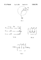
- FIG. 1 is a schematic diagram showing the cross section of a single wire carrying a current, and the resulting magnetic flux density it produces, together with the horizontal and vertical components of the flux density;
- FIG. 2a is a schematic diagram showing a star cable
- FIG. 2b shows its cross section and wire configuration
- FIG. 3 is a schematic cross section view of a star cable, when connected to a three-phase source, showing the magnitude and actual direction of current flows in the wires, at the moment when the flux density surrounding the cable is maximum;
- FIG. 4 is a cross section view of a star cable, when connected to a three-phase source, showing the magnitude and direction of current flow and the resulting flux density components at one point, when the flux density is maximum;
- FIG. 5 is a schematic diagram showing the flux density pattern surrounding a star cable when the flux density is maximum
- FIG. 6 is a schematic diagram showing the essential elements of the extra-low-voltage heating system covered by the present invention.
- FIG. 7 is a schematic diagram showing the monitoring system that checks the integrity of the extra-low-voltage heating system
- FIG. 8 is a schematic diagram showing in greater detail the cables and feeder of a 3-phase extra-low-voltage heating system but wherein the monitoring system is not shown;
- FIG. 9a is a schematic diagram of four adjacent 3-phase cable runs wherein the currents in correspondingly-located wires have the same magnitude and same direction, giving rise to a 3-phase similar-flow configuration.
- FIG. 9b is a schematic diagram of four adjacent 3-phase cable runs wherein the currents in correspondingly-located wires have the same magnitude but alternately flow in opposite directions, giving rise to a 3-phase alternate-flow configuration.
- FIG. 10 is a schematic diagram of two star cables each comprising four cable runs, connected to a three-phase feeder and wherein a similar-flow configuration is obtained at an instant when the flux density is maximum.
- FIG. 11 is a schematic diagram showing the cross section and similar-flow configuration of three adjacent star cable runs laid out on a common plane, together with representative flux density patterns at the moment when the flux densities (created by the 3-phase currents), are maximum;
- FIG. 12 is a schematic diagram of of one embodiment of the monitoring system
- FIG. 13a is a schematic diagram of a star cable showing its mode of connection to a single-phase feeder
- FIG. 13b is a cross section view of a star cable, showing the magnitude and direction of the single-phase current flows in the wires at the moment when the flux density surrounding the cable is maximum;
- FIG. 14 is a cross section view of a star cable when connected to a single-phase source, showing the magnitude and direction of current flows in the wires and the resulting components of flux density at one point, at the moment when the flux density surrounding the cable is maximum;
- FIG. 15 is a schematic drawing showing the flux density pattern surrounding a star cable when connected to a single-phase source
- FIG. 16a is a schematic diagram of four adjacent single-phase cable runs wherein the currents in correspondingly-located wires have the same magnitude and same direction, giving rise to a single-phase similar-flow configuration.
- FIG. 16b is a schematic diagram of four adjacent single-phase cable runs wherein the currents in correspondingly-located wires have the same magnitude but alternately flow in opposite directions, giving rise to a single-phase alternate-flow configuration.
- FIG. 17 is a schematic diagram showing in cross section a similar-flow configuration of three adjacent cable runs, laid out on a flat surface, when the star cables are connected to a single-phase source, together with representative flux density patterns;
- FIG. 18a shows the magnetic flux density distribution above a heated floor when the star cables are connected to a 3-phase source, in a similar-flow configuration
- FIG. 18b shows the magnetic flux density distribution above a heated floor when the star cables are connected to a 3-phase source, in an alternate-flow configuration
- FIG. 19a shows the magnetic flux density distribution above a heated floor when the star cables are connected to a single-phase source in a similar-flow configuration
- FIG. 19b shows the magnetic flux density distribution above a heated floor when the star cables are connected to a single-phase source in an alternate-flow configuration
- FIG. 20 is a cross section view of a single-phase feeder of the prior art
- FIG. 21 is a cross section view of a special single-phase three-bar feeder that is part of this invention.
- FIG. 22 is a schematic diagram of a single-phase heating system using a three-bar feeder, and showing the method of connecting the star heating cables thereto.
- FIG. 1 there is shown the cross section of a single wire carrying an alternating current having an instantaneous value I.
- the "cross" of the conventional dot/cross notation indicates that the current is flowing into the page.
- the value of the flux density is given by: ##EQU2##
- FIG. 2a is a schematic diagram showing a cable having three straight wires 1, 2, 3, that are parallel and in close proximity to each other.
- the cable has a length L A .
- wires 1, 2, 3 are connected together at junction N while connecting leads a, b, c at a near end, are connected to a 3-phase source (not shown).
- the wires are therefore connected in star.
- I call this a star cable.
- the wires carry 3-phase sinusoidal alternating currents I A , I B , I C , which respectively flow in the wires 1, 2, 3, as shown in the Figure.
- the line currents flowing in connecting leads a, b, c reach peak values of I S3 where subscript S stands for star and subscript 3 stands for 3-phase source.
- FIG. 2b is a cross section view of the star cable, showing the preferred configuration of the three wires, arranged in a single row along a horizontal axis.
- Wires 1, 2, 3 are coplanar and the distance between adjacent wires in each row is d. Distances d are measured between the centers of the wires.
- Outer wires 1 and 3 are respectively on the left-hand side and right-hand side of inner wire 2.
- the flux density surrounding the cable changes from instant to instant but it reaches a maximum during each half cycle.
- the flux density surrounding the cable is maximum when the current in the inner wire 2 is zero.
- the currents in the outer wires flow in opposite directions.
- FIG. 3 when current in wire 1 flows into the page, the current in wire 3 flows out of the page (toward the reader).
- the currents will have the same magnitudes but their respective directions will be the opposite to that shown in FIG. 3.
- I S3 peak line current of the star cable, A!
- FIG. 5 is a pictorial representation of Eqs. (7), (8) and (9), and shows in greater detail the nature of the flux density pattern surrounding the three-phase star cable when the flux density is maximum.
- a set of hypothetical rays such as 4, 6, 7, 8, centered at geometric center G and spaced at intervals of 22.50, are superposed on the three-wire cable.
- the flux orientation associated with each ray is shown by a short arrow.
- the flux density vector 4' is directed vertically upwards everywhere along the ray.
- Equation (7) reveals that the flux density along each ray decreases inversely as the square of the distance x from the geometric center G. Consequently, the flux density along any ray decreases rapidly with increasing values of x. However, for any given ray the orientation of the flux density vector with respect to the said horizontal axis remains fixed. The magnitude of the flux density at a given point also depends linearly upon the spacing d between adjacent wires; the closer the spacing the lower the flux density. For a given cable, the spacing is obviously fixed.
- FIG. 6 reveals the basic elements of the extra-low-voltage heating system covered by this invention.
- a surface area 9 is heated by means of a plurality of three-phase cables 10 that are connected to a three-phase feeder 11 by means of connections 12.
- the feeder is powered by a three-phase stepdown transformer 13 that is connected on its primary side to a 3-phase supply line 14 by means of circuit-breaker 15.
- the secondary line-to-line voltage is 30 V or less, to keep the system in the extra-low-voltage class.
- each heating cable 10 consists of three insulated wires that are in close proximity to each other.
- the cables develop a thermal power of PC watts per unit length.
- the value of PC depends upon several factors, such as the feeder voltage, the wire size, the length of cable and the resistivity of the wire material.
- the cable lengths are set so that the resulting value of PC maintains the temperature of the wires at or below the rated temperature of the cable.
- the rated temperature is typically less than 90° C.
- the cable runs are spaced at such a distance D R from each other so as to develop the desired thermal power density P D required by the heated surface area.
- D R is given by:
- each cable makes three contiguous runs, labeled 16.
- the voltage between busbars along the length of the feeder 11 is essentially constant and equal to 30 V or less.
- the feeder current at the transformer terminals is equal to the sum of the currents drawn by the cables. It is clear that the current in the feeder decreases progressively from a maximum at the transformer terminals to zero at the far end of the feeder. Consequently, the magnetic flux density surrounding the feeder reaches its greatest value near the transformer.
- FIG. 7 is another embodiment of the heating system of the present invention wherein a monitoring network is added.
- each heating cable contains, in addition to its heating wires, a bare metallic sensing wire or braid 17, shown dotted.
- Each sensing wire is connected at point 18 to a single insulated conductor 19 that follows the general direction of the feeder and terminates at a monitoring device 20.
- This low-power device applies a voltage between the sensing wires and the respective heating wires of the cables. If for any reason the insulation between a sensing wire and the heating wires of a cable should become damaged, a small current will flow, causing the monitoring device to trip circuit breaker 15. As a result, the heating system will be shut down. The nature of this monitoring device will be explained later in this disclosure.
- FIG. 8 shows in greater detail the method of connecting the 3-wire cables to a conventional 3-phase feeder having three busbars A, B, C.
- the cables have a single run.
- the three leads a, b, c of each cable are connected to busbars A, B, C. Care is taken to make all connections the same.
- the connecting leads a, b, c must be marked (such as by color coding), to ensure that the correct leads are connected to the respective busbars.
- one of the flat sides of the cable, parallel to the horizontal axis must also bear a marking. The reason is that proper lead connections and proper cable configurations are needed to minimize the flux density in regions close to the heated surface.
- proper cable configuration means that the horizontal axes of the cables are coplanar and lie substantially parallel to the plane of the surface to be heated.
- Proper cable configuration also comprises the proper instantaneous direction of current flow in successive cable runs at the instant when the flux density is maximum.
- FOG. 3 the maximum flux density of each cable occurs when the current in the inner wire is momentarily zero.
- the currents in the outer wires are then equal in magnitude but flow in opposite directions.
- FIG. 9a is a cross section view of a portion of a heated surface showing four representative adjacent cable runs wherein the currents in the inner wires are momentarily zero.
- the magnitudes and directions of the currents flowing in correspondingly-located wires are respectively the same.
- currents I A1 , I A2 , I A3 , I A4 flowing in the outer wires on the left-hand side of each run are substantially equal, and flow in the same direction, into the paper.
- currents I C1 , I C2 , I C3 , I C4 flowing in the outer wires on the right-hand side of each run are substantially equal and flow in the same direction, out of the paper.
- I call this a 3-phase similar-flow configuration.
- FIG. 9b is a cross section view of a portion of yet another heated surface showing four representative adjacent cable runs wherein the currents in the inner wires are again momentarily zero.
- the directions of current flows in correspondingly-located outer wires are alternately opposite.
- currents I' A1 , I' A2 , I' A3 , I' A4 flowing respectively in the outer wires on the left-hand side of each run have substantially the same magnitudes, but flow in successively opposite directions, into and out of the paper.
- FIG. 10 shows how two star cables, each comprising four contiguous runs, can be arranged to obtain the 3-phase similar-flow configuration when the flux density is maximum.
- the current flowing in the respective inner wire connecting leads b is then zero.
- the loops at the end of each run are folded as illustrated; the grey color marking along one of the flat sides of the cable constitutes a visual indication of the proper cable configuration.
- the flux density at a given point perpendicular to the heated surface area can be calculated.
- Eqs. (7), (8), (9) can be applied to each run, and the respective horizontal and vertical components of flux density can be summed. Consequently, the resultant flux density at the given point can be found.
- the flux density tends to reach local peaks immediately above the cable runs.
- FIG. 11 shows the flux density patterns of three adjacent cable runs G 1 , G 2 , G 3 having geometric centers that are also labeled G 1 , G 2 , G 3 .
- the instant is selected when the flux density is maximum. Consequently, the currents in the inner wires are zero and the flux density pattern for each cable is the same as that previously illustrated in FIG. 5.
- the currents in correspondingly-located wires have the same magnitudes and directions, and so this is a similar-flow configuration.
- Hypothetical rays also fan out at 22.5° intervals from the geometric centers of cables G 2 , G 3 .
- the 22.5° ray 22 and the 157.5° ray 23 intersect at point A.
- the 45° and 135° rays 24 and 25 intersect at point B.
- the flux density can be substantially less than that due to one cable alone, for heights H less than D R above the plane of the cables. If an alternate-flow configuration were used, the flux densities close to the heating surface would tend to be considerably larger, as demonstrated by reference to Example 3, in the section on Examples and Test Results.
- FIG. 7 illustrated the essential elements of a monitoring system.
- FIG. 12 shows one embodiment whereby the bare sensing wires 17 running along the length of each heating cable can be used to detect the integrity of the 3-phase heating system.
- the bare wires 17 are connected to a single insulated conductor 19 which follows the main feeder 11 back to the monitoring device 20.
- the latter consists of switches S1 and S2, a lamp L, a diode D, a capacitor C and a dedicated ac source 29.
- the heating wires and the bare sensing wire of each cable are contained within a plastic sheath.
- the sensing wire is therefore in close proximity to the heating wires. Consequently, if a cable is damaged, such as may happen if a hole is pierced in a floor, a contact will be established between the bare wire and at least one of the heating wires.
- a 120 V, 60 Hz ac source 29 charges a capacitor C to a potential of about 170 V dc by means of a diode D.
- a lamp L is connected in series with an electronic switch S1 that closes repeatedly at intervals, say, of once per second. If the heating system is intact, the periodic application of 170 V dc between the bare wires and the heating wires will have no effect and the lamp will not light up. But if a fault or short-circuit occurs between a bare wire and any one of the heating wires in the cable, the lamp will blink repeatedly at a rate of once per second, as the capacitor discharges through the lamp into the short circuit.
- the lamp is short-circuited by means of switch S2, a procedure that greatly increases the capacitor discharge current through the fault.
- the resulting pulsating magnetic field created around the insulated conductor 19 and around the defective cable can be detected by a portable magnetic pick-up.
- the location of the fault can be determined. It is understood that many other means, utilizing the sensing wire concept, can be devised to monitor a heating system, and to determine the location of a fault.
- FIG. 13a The preferred single-phase connection of a star cable is shown in FIG. 13a.
- connecting leads a and c of outer wires 1, 3 are connected to one busbar 30 of a single-phase feeder, while connecting lead b of inner wire 2 is connected to the other busbar 31. Leads a and c are therefore in short-circuit and a single-phase voltage E is applied to the cable.
- the outer wires 1, 3 are now effectively connected in parallel, and the said parallel connection is in series with inner wire 2.
- the arbitrary positive directions of currents I A I B and I C that flow in the wires are shown in FIG. 13a.
- the wires have the same cross section; consequently, currents I A and I C each have magnitudes that are substantially one-half that of current I B .
- the currents in all three wires attain their respective peak values at the same time. As a result, the maximum flux density is attained when the line current I B reaches its maximum positive (or negative) value.
- I B The peak value of I B is equal to I S1 , where I S1 , is the peak line current drawn by the cable from the single-phase feeder.
- I S1 is the peak line current drawn by the cable from the single-phase feeder.
- the subscripts S and 1 in I S1 respectively stand for star cable and 1-phase source.
- I S1 peak line current drawn by the single-phase star cable A!
- ⁇ angle between the horizontal axis of the cable and the ray joining its geometric center to the point of said maximum flux density 0!;
- FIG. 15 shows in greater detail the nature of the flux density pattern surrounding the cable.
- a set of hypothetical rays, centered at G 1 and spaced at intervals of 30°, are superposed on the three-wire cable.
- the flux density orientation associated with each ray is shown by a short arrow.
- the flux density vectors at every point along ray 35 are directed horizontally to the left, as indicated by representative flux density vector 35'.
- the representative flux density vector 36' is directed horizontally to the right at every point along vertical ray 36, because this ray is inclined at 90° to the horizontal axis.
- Equation (11) reveals that the flux density decreases inversely as the cube of the distance from the geometric center G. Thus, the flux density decreases very rapidly with increasing x. The magnitude of the flux density also depends upon the fixed spacings d between the wires; the closer the spacing the lower the flux density. To obtain the results predicted by Eqs. (11), (12) and (13) it is essential that the wires (and the currents they carry) be configured as described above.
- proper cable configuration means that the horizontal axes of the cables are coplanar and lie substantially parallel to the plane of the surface to be heated.
- Proper cable configuration also comprises the proper instantaneous direction of current flow in successive cable runs at the instant when the flux density is maximum.
- FIG. 13b we recall (FIG. 13b) that the maximum flux density of each cable occurs when the current in the inner wire is instantaneously at its peak.
- the currents in the outer wires flow in the opposite direction to that in the inner wire and have respectively half its magnitude.
- FIG. 16a is a cross section view of a portion of a heated surface, fed by a single-phase source, showing four representative adjacent cable runs wherein the currents in the inner wires are momentarily at their peak.
- the magnitudes and directions of the currents flowing in correspondingly-located wires are respectively the same.
- currents I A1 , I A2 , I A3 , I A4 flowing in the outer wires on the left-hand side of each run are substantially equal, and flow in the same direction, out of the paper.
- FIG. 16b is a cross section view of a portion of yet another heated surface showing four representative adjacent cable runs wherein the currents in the inner wires are again momentarily maximum.
- the direction of current flows in correspondingly-located wires of successive cable runs are alternately opposite.
- currents I' A1 , I' A2 , I' A3 , I' A4 flowing in the outer wires on the left-hand side of each run are substantially equal in magnitude, but flow alternately in opposite directions.
- FIG. 17 shows, in cross section, three adjacent cable runs G 1 , G 2 , G 3 , whose geometric centers are also labeled G 1 , G 2 , G 3 .
- the cable runs are laid out on a flat surface and spaced at a distance D R .
- the cables are powered by a single-phase source and their flux density patterns are similar to the pattern illustrated in FIG. 15.
- the cables are laid out and configured in such a way that their horizontal axes are coplanar and lie parallel to the plane of the heated surface, as shown in FIG. 17.
- the cables are arranged so that the magnitudes and directions of current flows in correspondingly-located wires of adjacent cable runs are substantially the same.
- the cable configuration is therefore of the single-phase similar-flow type.
- the single-phase similar-flow configuration of FIG. 17 is a preferred embodiment of this invention because it tends to reduce the flux density in the regions near the heated surface, namely those situated at heights H below 1.7 D R , perpendicular to the horizontal axes of the cables.
- the heating cables In addition to low flux densities, the heating cables must meet the requirements listed in the objectives of this invention. Thus, they must be robust, operate at temperatures below 90° C., and be as long as possible in order to reduce the number of cables that have to be connected to the feeder. Another objective is that the cables should be standardized as to wire size, wire material, and wire configuration so that a particular type of cable may be used in different heating installations. In order to meet these objectives and to evaluate the interaction of the various requirements, we postulate the parameters listed in Table 2. They are common to the two cable applications revealed in this disclosure (3-phase star, single-phase star).
- Table 3 row (2), reveals that the length of individual cables depends on E, A, P C and ⁇ , multiplied by a numerical coefficient that depends upon the type of source, i.e. three-phase or single-phase.
- the total cross section A of the three wires should not be too small. Typical values for surface heating range from 5 mm 2 to 10 mm 2 . However, for special applications, smaller or larger values can be employed.
- the voltage E is low, being 30 V or less. Consequently, according to the formulas in row (2), the cable lengths tend to be short, which is a disadvantage. The question now arises as to what values of P C and ⁇ should be used.
- the total length of all the heating cables is equal to P/PC .
- this total length should be as small as possible, which means that P C should be as large as possible.
- P C the value of P C is limited to a maximum P Cmax that depends upon the maximum allowable temperature of the cable as well as the environmental conditions, such as the ambient temperature and the emplacement of the cables.
- the length of the individual cables can still be tailored to a desired value by using an appropriate value for P C and a voltage E that is 30 V or less.
- the ability to tailor the individual cable lengths is important because surface-heating systems are preferably composed of runs of equal length, such as shown in FIG. 6.
- a three-conductor No. 14 AWG gauge cable was embedded in a concrete slab and then subjected to snow-melting conditions. It was discovered that a current of 42 A could be circulated through the wires without exceeding the temperature limit of 60° C. This test corresponds to a thermal power of 50 watts per meter.
- P c can range between 20 W/m and 50 W/m depending upon the type of cable, the ambient temperature and the emplacement of the cable.
- P D it ranges from 100 W/m 2 (10 W/ft 2 ) for room heating to 500 W/m 2 (50 W/ft 2 ) for snow melting.
- the cable spacings D R will typically range from 0.1 m (4 in) to 0.2 m (8 in).
- FIG. 18a shows the flux distribution above a long, narrow floor that is 84 inches wide and heated by twenty cable runs spaced at 4 inch intervals.
- the first cable run is located 4 inches from the left-hand edge of the floor and the twentieth cable run is 4 inches from the right hand edge.
- the heating system has the following specifications:
- FIG. 18a shows that at a height H of 100 mm ( ⁇ 4 in), the flux density is less than 40 mG over most of the width of the floor and rises to about 90 mG at the edges.
- the flux distribution was obtained by computer simulation, based on Eq. (1).
- the height of 100 mm falls within the prescribed range H ⁇ D R , i.e. H ⁇ 101.6 mm, wherein the flux density is reduced, as predicted in the disclosure.
- FIG. 18b shows the flux density at a height of 100 mm above the plane of the cables when the 3-phase alternate-flow configuration is employed.
- the flux density is now close to 90 mG over most of the width of the heated surface area, as compared to the 40 mG level seen in FIG. 18a.
- FIG. 19a shows the flux distribution above the same floor as in Example 3 except that the power source is single-phase and the star cables are connected accordingly, as shown in FIG. 13. All the cables are assumed to have single runs, and are connected to the feeder to produce a single-phase similar-flow configuration.
- the current is set to 57 A by tailoring the length of the cable and, if necessary, by adjusting the line voltage E.
- FIG. 19a shows that at a height of 100 mm ( ⁇ 4 in), the maximum flux density is approximately 1 mG over most of the width of the floor and rises to about 2.5 mG at the edges.
- the flux distribution was obtained by computer simulation, based on Eq. (1).
- the peak flux density created by a single cable at a distance x of 100 mm from its geometric center can be calculated by using Eq (11).
- This individual-cable flux density is 4 times greater than the 1 mG that appears over most of the floor at a height H of 100 mm. Consequently, the single-phase similar-flow configuration, as postulated in the disclosure, is a beneficial factor in reducing the flux density above a heated floor.
- FIG. 19 We have seen (FIG. 19) that the magnetic flux density above a surface area heated by a group of single-phase star cables can be quite small. However, this weak field may be overwhelmed by the strong magnetic field surrounding the feeder that supplies power to the cables.
- FIG. 13a shows a portion of a heating system wherein a conventional single-phase feeder 32, delivers power to one of a plurality of star cables distributed along its length.
- the busbars 30, 31 may eventually carry peak currents of several hundred amperes at points near the step-down transformer. This creates a problem as far as the magnetic field surrounding the feeder is concerned.
- the feeder 32 is usually composed of two busbars, traditionally stacked as shown in FIG. 20, which is a cross section view. A thin strip of insulation 41 separates the respective busbars 30, 31, labeled A, B.
- each copper bar is 48 mm (2 in) wide and 12 mm (0.5 in) thick, separated by an insulating strip of 3 mm.
- Such a feeder can carry an RMS (root mean square) current of about 1000 A.
- the feeder produces the approximate peak flux densities shown in Table 4, wherein the values were obtained by computer simulation. Distances are measured from the geometric center of the feeder.
- FIG. 21 shows a cross section view of this special feeder, which has three copper bars instead of two. In effect, the current formerly carried by busbar B is now carried by two outer bars B1, B2 having half the thickness of the original busbar.
- the copper bars are stacked in a special way, as shown in FIG. 21, with central bar A sandwiched between outer bars B1 and B2.
- FIG. 22 shows that at one end of the feeder, bars B1, B2 are connected to terminal Y of transformer 13, and bar A is connected to terminal X.
- This three-bar configuration produces the flux densities shown in Table 5, when the peak single-phase current delivered by the transformer is again 1000 A.
- FIG. 22 shows how the heating cables are connected to the three-bar feeder 42.
- the connecting lead of the inner wire of each cable is connected to the central busbar.
- the connecting leads of the outer wires on the left-hand side and right-hand side of each cable are respectively connected to busbars B1 and B2. This ensures substantially equal RMS currents in bars B1, B2, at any given point along the feeder.
- the special configuration of the star cables (FIG. 13a) ensures that the current in the central bar is substantially twice that in the outer bars.
- the present invention includes this special single-phase feeder as part of the extra-low-voltage heating system.
Landscapes
- Control Of Resistance Heating (AREA)
- Resistance Heating (AREA)
- Central Heating Systems (AREA)
Priority Applications (2)
| Application Number | Priority Date | Filing Date | Title |
|---|---|---|---|
| CA002179677A CA2179677C (fr) | 1996-06-21 | 1996-06-21 | Systeme de chauffage a tension extremement faible |
| US08/670,413 US5814792A (en) | 1996-06-21 | 1996-06-26 | Extra-low voltage heating system |
Applications Claiming Priority (2)
| Application Number | Priority Date | Filing Date | Title |
|---|---|---|---|
| CA002179677A CA2179677C (fr) | 1996-06-21 | 1996-06-21 | Systeme de chauffage a tension extremement faible |
| US08/670,413 US5814792A (en) | 1996-06-21 | 1996-06-26 | Extra-low voltage heating system |
Publications (1)
| Publication Number | Publication Date |
|---|---|
| US5814792A true US5814792A (en) | 1998-09-29 |
Family
ID=25678517
Family Applications (1)
| Application Number | Title | Priority Date | Filing Date |
|---|---|---|---|
| US08/670,413 Expired - Fee Related US5814792A (en) | 1996-06-21 | 1996-06-26 | Extra-low voltage heating system |
Country Status (2)
| Country | Link |
|---|---|
| US (1) | US5814792A (fr) |
| CA (1) | CA2179677C (fr) |
Cited By (12)
| Publication number | Priority date | Publication date | Assignee | Title |
|---|---|---|---|---|
| US6303905B1 (en) * | 2000-08-25 | 2001-10-16 | Bask Technologies Llc | Heating element construction for floor warming systems |
| US6483990B1 (en) * | 1995-09-07 | 2002-11-19 | Bar-Keser Project Management Initiatives And Economic Consultants | Electric heating devices and elements |
| US6704497B2 (en) | 1995-09-07 | 2004-03-09 | Bar-Keser Project Management Initiatives And Economic Consultants (1991) Ltd. | Electric heating devices and elements |
| US6734404B2 (en) | 2002-03-21 | 2004-05-11 | The Boeing Company | Heating elements with reduced stray magnetic field emissions |
| FR2874782A1 (fr) * | 2004-08-26 | 2006-03-03 | Brevetix Sarl | Dispositif de chauffage de terrains, notamment de sport |
| WO2006045964A1 (fr) * | 2004-10-28 | 2006-05-04 | Fernand Scherrer | Dispositif de chauffage de sols, notamment recouverts d'un revetement de synthese |
| US7071446B1 (en) * | 2005-08-01 | 2006-07-04 | Bench Steven D | De-icing, snow melting and warming system |
| US20090316753A1 (en) * | 2008-06-23 | 2009-12-24 | Bulatowicz Michael D | Temperature system with magnetic field suppression |
| WO2012045930A1 (fr) * | 2010-10-08 | 2012-04-12 | Ilo Technology Sas | Film chauffant avec un raccordement électrique alimenté en courant triphasé |
| US20140292091A1 (en) * | 2010-12-16 | 2014-10-02 | Conductix-Wampfler Gmbh | Device for the inductive transmission of electrical energy |
| US20150021315A1 (en) * | 2013-07-17 | 2015-01-22 | Blanke Gmbh & Co. Kg | Combined decoupling and heating system |
| US20150194251A1 (en) * | 2014-01-07 | 2015-07-09 | University-Industry Cooperation Group Of Kyung Hee University | Apparatus for enhancing power efficiency |
Citations (17)
| Publication number | Priority date | Publication date | Assignee | Title |
|---|---|---|---|---|
| US2042742A (en) * | 1932-06-15 | 1936-06-02 | Taylor Joseph Henry | Electrical heating system for buildings |
| US2287502A (en) * | 1941-06-12 | 1942-06-23 | Bulldog Electric Prod Co | Electrical distribution system |
| US3213300A (en) * | 1963-07-01 | 1965-10-19 | Ite Circuit Breaker Ltd | Location of neutral and ground bus bar in low reactance bus duct assembly |
| US3223825A (en) * | 1958-03-21 | 1965-12-14 | Chester I Williams | Electric grid floor heating system |
| US3364335A (en) * | 1963-05-31 | 1968-01-16 | Palatini Benno | Device for electrically heating surface structures such as roads, bridges, airport runways, walls, and the like |
| US4262215A (en) * | 1979-05-10 | 1981-04-14 | Tokyo Shibaura Denki Kabushiki Kaisha | Direct current interrupter |
| US4547658A (en) * | 1984-06-13 | 1985-10-15 | Sunbeam Corporation | Multiple heat fusing wire circuit for underblankets |
| US4556874A (en) * | 1981-08-21 | 1985-12-03 | Linder Gmbh Fabrik Elektrischer Lampen Und Apparate | Fusible circuit breaker |
| US4908497A (en) * | 1988-03-25 | 1990-03-13 | Kanthal Ab | Flat electrical resistance heating element |
| US4998006A (en) * | 1990-02-23 | 1991-03-05 | Brandeis University | Electric heating elements free of electromagnetic fields |
| US5068543A (en) * | 1990-11-14 | 1991-11-26 | General Atomics | Low hazard extremely low frequency power transmission line |
| US5081341A (en) * | 1988-08-29 | 1992-01-14 | Specialty Cable Corp. | Electrical heating element for use in a personal comfort device |
| US5218507A (en) * | 1990-09-06 | 1993-06-08 | Ashley James R | Overhead three-phase power line eliminating fringing electric and magnetic fields |
| US5218185A (en) * | 1989-08-15 | 1993-06-08 | Trustees Of The Thomas A. D. Gross 1988 Revocable Trust | Elimination of potentially harmful electrical and magnetic fields from electric blankets and other electrical appliances |
| US5360998A (en) * | 1991-03-29 | 1994-11-01 | General Electric Company | Magnetic field minimization in power transmission |
| US5403992A (en) * | 1992-04-11 | 1995-04-04 | Imetec S.P.A. | Electrically heated panels |
| US5410127A (en) * | 1993-11-30 | 1995-04-25 | Larue; John D. | Electric blanket system with reduced electromagnetic field |
-
1996
- 1996-06-21 CA CA002179677A patent/CA2179677C/fr not_active Expired - Fee Related
- 1996-06-26 US US08/670,413 patent/US5814792A/en not_active Expired - Fee Related
Patent Citations (17)
| Publication number | Priority date | Publication date | Assignee | Title |
|---|---|---|---|---|
| US2042742A (en) * | 1932-06-15 | 1936-06-02 | Taylor Joseph Henry | Electrical heating system for buildings |
| US2287502A (en) * | 1941-06-12 | 1942-06-23 | Bulldog Electric Prod Co | Electrical distribution system |
| US3223825A (en) * | 1958-03-21 | 1965-12-14 | Chester I Williams | Electric grid floor heating system |
| US3364335A (en) * | 1963-05-31 | 1968-01-16 | Palatini Benno | Device for electrically heating surface structures such as roads, bridges, airport runways, walls, and the like |
| US3213300A (en) * | 1963-07-01 | 1965-10-19 | Ite Circuit Breaker Ltd | Location of neutral and ground bus bar in low reactance bus duct assembly |
| US4262215A (en) * | 1979-05-10 | 1981-04-14 | Tokyo Shibaura Denki Kabushiki Kaisha | Direct current interrupter |
| US4556874A (en) * | 1981-08-21 | 1985-12-03 | Linder Gmbh Fabrik Elektrischer Lampen Und Apparate | Fusible circuit breaker |
| US4547658A (en) * | 1984-06-13 | 1985-10-15 | Sunbeam Corporation | Multiple heat fusing wire circuit for underblankets |
| US4908497A (en) * | 1988-03-25 | 1990-03-13 | Kanthal Ab | Flat electrical resistance heating element |
| US5081341A (en) * | 1988-08-29 | 1992-01-14 | Specialty Cable Corp. | Electrical heating element for use in a personal comfort device |
| US5218185A (en) * | 1989-08-15 | 1993-06-08 | Trustees Of The Thomas A. D. Gross 1988 Revocable Trust | Elimination of potentially harmful electrical and magnetic fields from electric blankets and other electrical appliances |
| US4998006A (en) * | 1990-02-23 | 1991-03-05 | Brandeis University | Electric heating elements free of electromagnetic fields |
| US5218507A (en) * | 1990-09-06 | 1993-06-08 | Ashley James R | Overhead three-phase power line eliminating fringing electric and magnetic fields |
| US5068543A (en) * | 1990-11-14 | 1991-11-26 | General Atomics | Low hazard extremely low frequency power transmission line |
| US5360998A (en) * | 1991-03-29 | 1994-11-01 | General Electric Company | Magnetic field minimization in power transmission |
| US5403992A (en) * | 1992-04-11 | 1995-04-04 | Imetec S.P.A. | Electrically heated panels |
| US5410127A (en) * | 1993-11-30 | 1995-04-25 | Larue; John D. | Electric blanket system with reduced electromagnetic field |
Non-Patent Citations (2)
| Title |
|---|
| Documentaiton of the Threshold Limit Values, "For Physical Agents in the Work Environment", ACGIH, pp. PA-iii; PA-1 and PA-55 to PA-64. |
| Documentaiton of the Threshold Limit Values, For Physical Agents in the Work Environment , ACGIH, pp. PA iii; PA 1 and PA 55 to PA 64. * |
Cited By (25)
| Publication number | Priority date | Publication date | Assignee | Title |
|---|---|---|---|---|
| US6483990B1 (en) * | 1995-09-07 | 2002-11-19 | Bar-Keser Project Management Initiatives And Economic Consultants | Electric heating devices and elements |
| US6704497B2 (en) | 1995-09-07 | 2004-03-09 | Bar-Keser Project Management Initiatives And Economic Consultants (1991) Ltd. | Electric heating devices and elements |
| US6303905B1 (en) * | 2000-08-25 | 2001-10-16 | Bask Technologies Llc | Heating element construction for floor warming systems |
| US6734404B2 (en) | 2002-03-21 | 2004-05-11 | The Boeing Company | Heating elements with reduced stray magnetic field emissions |
| US20070269193A1 (en) * | 2004-08-26 | 2007-11-22 | Milhail Erofeev | Device for Heating Grounds, in Particular Sports Ground |
| WO2006024797A1 (fr) * | 2004-08-26 | 2006-03-09 | Brevetix | Dispositif de chauffage de terrains, notamment de sport |
| CN101010988B (zh) * | 2004-08-26 | 2011-09-14 | 布勒弗泰公司 | 用于加热场地的装置 |
| NO339053B1 (no) * | 2004-08-26 | 2016-11-07 | Brevetix | Innretning for å varme plasser, særskilt sportsplasser |
| FR2874782A1 (fr) * | 2004-08-26 | 2006-03-03 | Brevetix Sarl | Dispositif de chauffage de terrains, notamment de sport |
| US7778532B2 (en) | 2004-08-26 | 2010-08-17 | Brevetix | Device for heating grounds, in particular sports ground |
| WO2006045964A1 (fr) * | 2004-10-28 | 2006-05-04 | Fernand Scherrer | Dispositif de chauffage de sols, notamment recouverts d'un revetement de synthese |
| FR2877535A1 (fr) * | 2004-10-28 | 2006-05-05 | Fernand Scherrer | Dispositif de chauffage de sols, notamment recouverts d'un revetement de synthese |
| US20090032525A1 (en) * | 2004-10-28 | 2009-02-05 | Fernand Scherrer | Soil-heating device particularly for soil covered by a synthetic surface |
| CN101091415B (zh) * | 2004-10-28 | 2010-05-26 | 费尔南·舍雷尔 | 特别用于合成表面所覆盖的土壤的土壤加热装置 |
| US7071446B1 (en) * | 2005-08-01 | 2006-07-04 | Bench Steven D | De-icing, snow melting and warming system |
| EP2138859A1 (fr) | 2008-06-23 | 2009-12-30 | Northrop Grumman Guidance and Electronics Company, Inc. | Système de température doté d'une suppression du champ magnétique |
| US8138760B2 (en) * | 2008-06-23 | 2012-03-20 | Northrop Grumman Guidance And Electronics Company, Inc. | Temperature system with magnetic field suppression |
| US20090316753A1 (en) * | 2008-06-23 | 2009-12-24 | Bulatowicz Michael D | Temperature system with magnetic field suppression |
| WO2012045930A1 (fr) * | 2010-10-08 | 2012-04-12 | Ilo Technology Sas | Film chauffant avec un raccordement électrique alimenté en courant triphasé |
| FR2965899A1 (fr) * | 2010-10-08 | 2012-04-13 | Ilo Technology | Film chauffant avec un raccordement electrique alimente en courant triphase |
| US20140292091A1 (en) * | 2010-12-16 | 2014-10-02 | Conductix-Wampfler Gmbh | Device for the inductive transmission of electrical energy |
| US9473211B2 (en) * | 2010-12-16 | 2016-10-18 | Conductix Wampfler Gmbh | Device for the inductive transmission of electrical energy |
| US20150021315A1 (en) * | 2013-07-17 | 2015-01-22 | Blanke Gmbh & Co. Kg | Combined decoupling and heating system |
| US20150194251A1 (en) * | 2014-01-07 | 2015-07-09 | University-Industry Cooperation Group Of Kyung Hee University | Apparatus for enhancing power efficiency |
| US9831015B2 (en) * | 2014-01-07 | 2017-11-28 | I To You | Apparatus for enhancing power efficiency |
Also Published As
| Publication number | Publication date |
|---|---|
| CA2179677C (fr) | 2000-07-11 |
| CA2179677A1 (fr) | 1997-12-22 |
Similar Documents
| Publication | Publication Date | Title |
|---|---|---|
| US5854472A (en) | Low-voltage and low flux density heating system | |
| US5814792A (en) | Extra-low voltage heating system | |
| Demoulias et al. | Ampacity of low-voltage power cables under nonsinusoidal currents | |
| US6049063A (en) | Low voltage wire mesh heating element | |
| US5811767A (en) | Three wire, three-phase heating cable and system | |
| US5515230A (en) | Poly-phase coaxial power line efficiency enhancements | |
| Thango et al. | A Novel Approach for Evaluating Eddy Current Loss in Wind Turbine Generator Step-Up Transformers | |
| JPS59205181A (ja) | 熱トレ−シングテ−プ及びパワ−制御システム | |
| Babu et al. | HVDS approach for reducing the Technical and Non-technical losses to enhance the Electrical Distribution System performance | |
| Zala | Comparative study and simulative analysis of high voltage and low voltage distribution systems for rural agricultural loads: Simulation using etap software | |
| US20070175879A1 (en) | Floor heating system | |
| CA2138868C (fr) | Systeme de chauffage a treillis metallique, a champ magnetique reduit | |
| Babu et al. | Operation and control of electrical distribution system with extra voltage to minimize the losses | |
| CN106411107B (zh) | 电力转换装置 | |
| US20110116212A1 (en) | Method of Recovering Power Losses In A Residential, Commercial, or Industrial Facility | |
| Kola et al. | Design Stage Diagnosis of Electrical Power Infrastructure (Building Systems) For Safe and Green Electricity. | |
| JP3174227U (ja) | 電磁誘導加熱装置 | |
| N Sultan et al. | Load Estimation and Design of Electrical Installation for Hotel in East Jerusalem | |
| Fairman et al. | Recent progress in distribution practise of the Brooklyn Edison Company, Inc. | |
| Scaddan | IET Wiring Regulations: Design and Verification of Electrical Installations | |
| Farag et al. | Electromagnetic fields in the home | |
| Fairman et al. | Recent Progress in Distribution Practise of the Brooklyn Edison Company, Inc. | |
| Demoulias et al. | Harmonics-induced problems in theatrical-lighting installation: Real-case measurements and proposed solutions | |
| Ke et al. | Analysis and mitigation of the electromagnetic coupling problem associated with multi-conductors in three-phase systems | |
| Stauffer | NFPA's Pocket Dictionary of Electrical Terms |
Legal Events
| Date | Code | Title | Description |
|---|---|---|---|
| AS | Assignment |
Owner name: SPERIKA ENTERPRISES LTD., CANADA Free format text: ASSIGNMENT OF ASSIGNORS INTEREST;ASSIGNOR:WILDI, THEODORE;REEL/FRAME:008686/0793 Effective date: 19960620 |
|
| CC | Certificate of correction | ||
| REMI | Maintenance fee reminder mailed | ||
| LAPS | Lapse for failure to pay maintenance fees | ||
| LAPS | Lapse for failure to pay maintenance fees |
Free format text: PATENT EXPIRED FOR FAILURE TO PAY MAINTENANCE FEES (ORIGINAL EVENT CODE: EXP.); ENTITY STATUS OF PATENT OWNER: SMALL ENTITY |
|
| STCH | Information on status: patent discontinuation |
Free format text: PATENT EXPIRED DUE TO NONPAYMENT OF MAINTENANCE FEES UNDER 37 CFR 1.362 |
|
| FP | Lapsed due to failure to pay maintenance fee |
Effective date: 20020929 |