US581223A - Hydeaulig brick press - Google Patents
Hydeaulig brick press Download PDFInfo
- Publication number
- US581223A US581223A US581223DA US581223A US 581223 A US581223 A US 581223A US 581223D A US581223D A US 581223DA US 581223 A US581223 A US 581223A
- Authority
- US
- United States
- Prior art keywords
- valve
- ram
- press
- pressure
- cylinder
- Prior art date
- Legal status (The legal status is an assumption and is not a legal conclusion. Google has not performed a legal analysis and makes no representation as to the accuracy of the status listed.)
- Expired - Lifetime
Links
- 239000011449 brick Substances 0.000 title description 5
- 230000007246 mechanism Effects 0.000 description 31
- 230000006835 compression Effects 0.000 description 19
- 238000007906 compression Methods 0.000 description 19
- 238000010276 construction Methods 0.000 description 18
- 239000004927 clay Substances 0.000 description 17
- XLYOFNOQVPJJNP-UHFFFAOYSA-N water Substances O XLYOFNOQVPJJNP-UHFFFAOYSA-N 0.000 description 11
- 230000001276 controlling effect Effects 0.000 description 10
- 230000000694 effects Effects 0.000 description 10
- 239000007788 liquid Substances 0.000 description 4
- 230000006872 improvement Effects 0.000 description 3
- 230000001105 regulatory effect Effects 0.000 description 3
- 239000012530 fluid Substances 0.000 description 2
- 230000000284 resting effect Effects 0.000 description 2
- 239000011435 rock Substances 0.000 description 2
- 241000120694 Thestor Species 0.000 description 1
- 230000015572 biosynthetic process Effects 0.000 description 1
- 230000001419 dependent effect Effects 0.000 description 1
- 238000010586 diagram Methods 0.000 description 1
- 210000004907 gland Anatomy 0.000 description 1
- 239000000463 material Substances 0.000 description 1
- 230000001151 other effect Effects 0.000 description 1
- 230000000630 rising effect Effects 0.000 description 1
Images




Classifications
-
- B—PERFORMING OPERATIONS; TRANSPORTING
- B29—WORKING OF PLASTICS; WORKING OF SUBSTANCES IN A PLASTIC STATE IN GENERAL
- B29C—SHAPING OR JOINING OF PLASTICS; SHAPING OF MATERIAL IN A PLASTIC STATE, NOT OTHERWISE PROVIDED FOR; AFTER-TREATMENT OF THE SHAPED PRODUCTS, e.g. REPAIRING
- B29C45/00—Injection moulding, i.e. forcing the required volume of moulding material through a nozzle into a closed mould; Apparatus therefor
- B29C45/17—Component parts, details or accessories; Auxiliary operations
- B29C45/84—Safety devices
Definitions
- Patents II II I are No. 581,223. Patents II II I:
- the present invention relates to improve ments in hydraulic brick-presses, and more particularly in that type of presses described in my application for Letters Patent, filed June 1, 1891, Serial No. 394,749; and the present improvement has for its object to provide successively and automatically operating connecting mechanisms between charger-cylinder and the upper and the lower ram cylinders, and inwhich the parts are provided with variedmeans of adjustment in order that action of the press can be modified and changed,
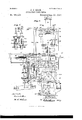
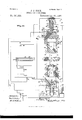
- FIG. 1 is a front elevation of the press, partly in section; Fig. 2, a longitudinal sectional elevation of the same at line 00 m, Fig. 3; Fig. 3, a horizontal section at line 00 as, Fig. 2; Fig. 4, an enlarged detail longitudinal sectional elevation of the valve-chest and valves of the charger-cylinder; Fig. 5, an enlarged detail transverse sectional elevation of high-pressure-regulating valve mechanism; Fig. 6, a detail side elevation of the latch mechanism for the valve mechanism of the chargercylinder; Fig. 7, a front elevation of the same.
- Fig. '8 is an enlarged detail longitudinal sectional elevation of the charger, charger-cylinder, and connections; Fig. 9, a side elevation of the samefpartly sectionized; Fig.
- FIG. 10 a detail plan view illustrating the arrangement of the cam plate that actuates the throttle-valve of the charger-cylinder;
- Fig. 11 an enlarged detail transverse sectional elevation of the press, illustrating the lockin g and unlocking mechanism for the valves of the operating-cylinder of the side pipe and the relief-valves of the upper ram;
- Fig. 12 a
- Fig. 18, of the side-pipe and relief valves and connections Fig. 17, a sectional front elevation of the same at line x 00 Fig. 16; Fig. 18, a detail plan view of the same.
- Figs. 19, 20, and 21 are detail sectional elevations illustrating the side-pipe-valve lever and connections in the different positions it assumes in different operations of the press;
- Fig. 22, a detail sectional elevation of the operating-cylinder and piston of the side-pipe and relief valve mechanism;
- Fig. 23 a longitudinal section of the same;
- Fig. 17 a sectional front elevation of the same at line x 00 Fig. 16
- Fig. 18, a detail plan view of the same.
- Figs. 19, 20, and 21 are detail sectional elevations illustrating the side
- Fig. 26 an enlarged detail section of the inlet and pressure-dividing valves and connections of the lower-ram cylinder;
- Fig. 27 an enlarged sectional elevation illustrating the valve and valve mechanism for the operating-cylinder of the side-pipe and relief valve mechanism and the operating mechanism for the valves of the auxiliary raising-cylinder of the upper rain;
- Fig. 28 an opposite detail elevation of the op erating mechanism of the valves of auxiliary raising-cylinder of the upper ram;
- Fig. 29 a central vertical section of the press through the rams and ram-cylinders with the valves and pipe connections illustrated in diagram.
- Fig. 30 is a detail horizontal section of the cylinder or housing of the upper ram, illustrating the ports or passages therein.
- FIG. 31 is a similar view of thecylinder or housing of the lower ram; Fig. 32, a detail perspective of the latch mechanism shown in Figs. 24. and 25. Fig. 33 is a detail elevation of the latch mechanism in a different position from that shown in Fig. 25.
- the press proper consists of the upper and lower lixed members] and 2, connected t egether in proper relative position by means of stay-sleeves, tie-rods, and nuts, as usual, and supported on a suitable frame or base, as shown, the mold-frame 3 being supported in the usual manner midway the height between the upper and lower fixed members 1 and 2 with the brick-receiving table 4 arranged in front thereof and the charger-table 5 at the rear of the same.
- the fixed members 1 and 2 constitute the hydraulic cylinders for .the main hydraulic plungers or rams t5 and '7, to which are attached the mold-plungers S and .l, by which the charge of clay is compressed in the moldcavity 10, (see Fig. 2E and 19 are the usual stops on the upper and lower rams that limit the respective movements of the rams.
- FIG. 11 is a circuitous port or passage in the upper lixed member 1, (see Figs. 1, 16, and 25,) having eonnnunication with the upper-ram chamber and with the side-pipe connection 12, the storage-tank 1b, and the relief-valve 11 in the following manner: with the sidepipe connection 12 through branch passage 15, controlled by a valve 16, (see Fig. 16,) with storage-tank. 13 through branch passages 17, controlled by the inlet-outlet valve 18, (see Figs. 1 and 25,) and with the relief-valve 11 by the branch 20, (see Fig. 1,) which may communicate with the storage-tank 13 or any other suitable receptacle.
- FIG. 21 is a eireuitrmsport or passage in the lower fixed member 2, (see Figs. 1, 2, 25, 2t and 25),) having communication with the lower-ram chamber and with the high and low pressure supplies 22 and 23, the storage-tank 13, and the side pipe 12, that connects with the upper-ram chamber, in the following manner: with the high and low pressure supplies through the branch passages 21 and 25, (see Fig. 20,) the respective connections of which are controlled by the pressuredividing valve 26, and the inlet-valve 27, and with the stor' age-tank 1-3 by a branch passage containing a valve 28. (See Figs. 1 and 2t As in my former construction and as illustrated in Figs.
- the upper ram or plunger 0 is connected by tie-rods 2! with the vertically-moving auxiliary cylinder 53 the piston 31 of which is stationary on the lixed press member 1, (see Fig. 25),) such piston being provided with the respective ports or passages 32 and 33, that respectively open or lead into the upper chamber 31 and annular chamber 35 of the auxiliary cylinder St in the present construction, so is an inwardly-opening check-valve in a passage communicating with the upper chamber 31 of the auxiliary cylinder, which is adapted to admit air and prevent a formation of a vacuum on the upward movement of the cylinder, as illustrated in Figs. 1, 2, and 29.
- the lower ram or plunger 7 (see Fig. l) is connected by tie-rods 37 with the verticallyinoving auxiliary cylinder 38, the piston 39 of which is stationary on the under side of the lower lixed member 2 (see Fig. 29) of the press, such piston being provided with a single port or passage -10, that introduces a constant pressure into the cylinder 38 and produces a constant downward pulling strain upon the lower-ram plunger 7 and the lower mold-plunger 9.
- 11 is the upper rock-shaft of the press, receiving motion from the upper vertically-moving auxiliary cylinder 30 through links 12 and arms 4-3, and provided with arms 11- and 15, that have connection with and operate the different press parts, as hereinafter described
- 10 is the lower rock-shaft, receiving motion from the lower vertically-moving auxiliary cylinder 38 through links 17 and arms 18, and provided with an arm if), that connects by a link with the arm 51 ot' a supplementary rockshatt 52.
- the supplementary rock-shaft 52 as illustrated in Figs. 1, 2, I and 27, is provided with arms 53, 51, (see Figs. 2 and 3,) and 55, (see Figs. 1 and 27,) that have connection with and operate different press parts, as hereinafter described.
- the intermediate rock-shaft 56 as illustrated in Figs. 1, 2, 3, 8, 0, 27, and 28, is provided with arms 57, (see 1, 2, 3, S, and $1,) through which it receives motion from the claycharger, as hereinafter set forth, and carries arms 58 (see Fig. 8) and 59 (see Figs. 27 and 28) and cams (50 (see Fig. 3) and U1, (see Fig. 2,) adapted to operate dit'terent press parts, as hereinafter described.
- the inlet-outlet valve 18 of the upper-ram chamber (see 1, 2t, 25, and 25)) is made separate or movable on its stem (see Fig. and capable of independent movement, in order that it may at the proper time act as a suction checkvalve for the upper-ram chamber, and thus perform the combined functions of the independent and distinct inlet-outlet valve 2 and suction check-valve 2i of the construction shown in my former applieatiol1,Serial No. 391,719, a suitable stop, as 02, (see Figs. 1 and 25,) being employed to limit the stroke of the valve when acting as suction check-valve.
- the movement of the valve as an inlet.- outlet valve for the upper-ram chamber is accomplished by the following mechanism:
- the slotted valve-stem (33 (see Figs. 1 and 25) is guided by the gland (51 at top and the bracket-piece at bottom, and carries a roller ⁇ it ⁇ , that is engaged by the cam-faced lever 07, (see Fig. 25,) having its fulcrum 011 the bracket-piece 65,with its lower end or heel in contact with the headed upper end oi. the intermediate rod ti8,(see Fig. 25,) that extends down into the path of a projection 69 on the lower ram 7.
- the rod 08 passes through a guide-orifice in the mold-frame and is provided at its lower end with an adjustable shoe 70, that projects into the path of the ram projection 60, in order to IOC admit of any desired adjustment in the relation of the parts to cause an opening of the valve 18 at the desired time.
- the opening of the valve 18 (see Figs. 24 and 25) is effected, and in order to hold it in an open condition I pivot to the bracket-piece or other suitable part of the press (see Figs. 24, 25, and 32) the weighted latch-piece 71, adapted to engage beneath a pin projection 72 on the slotted valve-stem 63 as the same reaches its raised position, such latch-piece being released at the proper time by a suitable connection with the upper ram.
- Figs. 25 and 33 I illustrate a hook-bar 73, pivoted to the upper ram 6 by a rule-joint or other equivalent mode of attachment.
- the hook 73 With the hook 73 in a pendent position, as shown in Fig. 25, the same will on the downward travel of the upper ram be engaged under the arm 74 of the latch-piece, and on the upward travel of said ram will draw the latch-piece 71 out of engagement with the valve-stem to allow the same to drop and the valve 18 to close.
- the hook-bar With the hook-bar swung into a horizontal position, as shown in Fig.
- the mechanism first above described is preferably used, in that it affords means for obtaining a maximum compression upon the upper side of the charge of clay.
- the inlet-outlet suction or triple valve 18 is opened by the upward movement of the lower ram and locked in such open condition by the latch-piece 71 during the downward travel of both the upper and lower rams. This will allow initial compression from the top ram.
- the water entering lower-ram chamber now compresses the clay sufficiently from the lower side to raise the mass of clay and the upper ram.
- the hook 73 detaches the latch-piece 71 from engagement with the valve-stem 63 and allows the same to drop, in turn permitting the triple valve 18 to close, thus stopping the upward travel of the upper ram and placing the same in such a relative position to the lower ram that pressure can be produced on both the upper and lower plungers or rams without having any resistance from the stops.
- the controlling-valve 16 between the upper and lower ram chambers, has its stem. 76 engaging a valvelever 77, fulcrumed on the fixed member 1 of the press, the valve-lever being operated at the proper times by a valve-rod 78, (see Fig. 16,) attached to the moving cylinder 79 (see Figs. 1, 2, 3, 22, and 23) of a water-engine.
- 80 and 81 see Fig. 16'are adjustable upper and lower collars or tappets on the valve-rod that are adapted, respectively, to draw down and lift up the free end of the valve-lever 77.
- a yoke-piece attached to the fixed member 1 of the press, having an adjust-able abutment 83 to limit the upward movement of the valve-lever 77 and the opening of the controlling-valve 16;
- a compressible abutment preferably having pivotal attachment to the fixed member 1 of the press, resiliency of which is made adj ustable by the temper screw and nut 85, as shown.
- the relief-valve 14 (see Fig. 16) of the up-' per-ram chamber has its stem 86 engaging a valve-lever 87, fulcrumed to the fixed press member 1, the valve-lever being drawn upward by a spring 88 and downward at the proper time by an adjustable collar or tappet 89 on the valve-rod 78, attached to the moving cylinder 79 (see Figs. 1, 2, 16, 22, and 23) of a Water-engine, the time of lowering and length of stroke depending upon the position of the collar 89.
- the water-engine for operating the controlling-valve 16 and relief-valve 14 has its cylinder 79 (see Figs. 22 and 23) arranged to move on guides 90, while its piston is stationary and provided with ports 91 and 92, that communicate, respectively, with the chambers 93 and 94 above and below the head of the piston, the port 92 being in continuous communication with the source of water-pressure, while the port 91 is connected with the valve-chest 95, (see Figs. 3 and 27,) the valves of which are operated by the valve mechanism hereinafter described.
- the relief-valve 14 first opens, and following the same at the proper time the controlling-valve 16 is closed, the relative cooperation of the two depending upon the position of the adjustable collar 80. (See Figs. 1, 2, 16, and 18.)
- controlling-valve 16 can be varied in various ways, so as to adapt the press to the many different qualities of clay and thus impart a. universal adaptability to the present improved construction of hydraulic brick-press.
- raising the controlling-valve lever 77 by means of the collar 81 the controlling-valve is fully opened to allow pressure to be effected on both hydraulic rams simultaneously in equal ratio.
- By restricting the opening of the controlling-valve by means ofthe adjustable abutment the pressure will increase in both rams in unequal ratio, although the final maximum pressure will be the same on both rams.
- Fig. 16 illustrates a loaded limited moving arrangement of the above parts with which the controlling-valve 16 will first open after a desired degree of pressure has been reached in the lower-ram chamber to overcome the resistance of the compressible abutment St. The controlling valve will then gradually open, depending upon the increase of pressure in the side pipe 12 and the relative compression of the abutment 81, until arrested by the adjustable abutment 83.
- Fig. 19 illustrates a limited moving arrangement of the said parts in which the primary opening of the controlling-valve is in sympathy with the water-pressure entering lower-' ram chamber and side pipe 12 and which is subsequently restricted by the compressible abutment 81', the gradual compression of which allows the controlling-valve to grad ually open until arrested by the stop 83.
- Fig. 20 illustrates an arrangement of such parts uninlluenced by the compressible abutment 84:, but with the opening of the controlling-valve limited by the adjustable abutment 83. ⁇ Vith this arrangement the waterpressure will enter the upper-ram chamber in a uniform stream during the time that the valve is open and until pressing is completed.
- Fig. 21 illustrates an arrangement of such parts with which the primary opening of the controlling-valve is uniniiueneed by the compressible abutment, but is subsequently i11- ilucnced by the same, so that the gradual opening of the controllingvalve is in sympathy with the gradual compression of the abutment 8t and is entirely unaffected by the adjustable abutment 83.
- the reciprocating clay-charger 96 (as illus tratcd in Figs. 2, 3, 4, 8, 9 and 10,) as in my formerapplication, is operated by a hydraulic piston and cylinder 97 and 98.
- the annular water-chamber 99 (see Fig. 8) of the cylinder 97 is in constant communication with the source of wa: tor-pressure, so that the tendency at all times is to draw the charger backward.
- the chamber 100 of said cylinder is in communication with the valve-ehest 101 (see Figs. 2, 3, and 4) and receives at proper times a pressure of water therefrom, so as to move the claycharger forward, such valve-chamber being formed with supply and exhaust valve chambers 102 and 103, (see Fig. 4,) containing the supply and exhaust valves 10$ and 105, the stems of which are connected to the rocklever 106 on arock-shaft 107 in any usual manner, so as to be capable of a limited independent movement.
- the rock-lever 106 is attached to its rockshatt 107 by a set-screw or other equivalent device, so as to be capable of being readily loosened upon said shaft when required, and is provided with a handle extension 108, (see Fig. 4,) the-construction being such that the lever can be loosened and operated independentl y by hand to actuate the clay-charger when desired without affecting the automatic mechanism by which the charger-valves are ordinarily operated.
- Each of the charger-valves 104 and 105 will have a primary or closing movement and a secondary or opening movement, the primary' movements being imparted to the rock-shaft 107 and its arm 109 (see Figs. 2 and 3) by a slotted adjustable link 110 and rock-arm 53, attached to supplementary rock-shat t 52, that receives motion from the lower ram, as heretoforedeseribed, the secondary movement being imparted to the rocleshaft 107 and its arm 109 by a link connection 111 and shifting overbalance device 112.
- a spring-latch adapted to engage the outer end of the arm 109 when the overbalancing device 112 is in the position indicated in dotted lines in Fig. 2 to hold the same against further downward movement until the spring-latch is released from such engagement by the upward movement of the upper ram 6, acting through links -12, arm 43, upper rock-shaft 41, arm L5, and rod 114:, provided with an adjustable block 115, adapted to engage the arm 116 of the IIO spring-latch 113 to release the same from its shifting overbalance device 112. so that it.
- 117 (see Figs. 9 and is a cam-plate attached to the clay-charger, the cam-face 118 of which is adapted to engage the stem of a throttle-valve 119, arranged in the inlet-passage to the rear chamber 100 of the chargercylinder, so as to regulate the speed or movement of charger.
- Motion is communicated to the arm 57 (see Fig. 9) of the intermediate rock-shaft 56 of the press by an adjustable tappet 120 in one direction and in the other direction by means of achain or other adjustable device 121, the ends of which are attached to the charger and to the end of the arm 57, respectively.
- 122 is a compressible abutment attached to the press proper and located in the path of the arm 58 on the intermediate rock-shaft 56, the purpose of which is to afford an emergency stop for the forward movement of the clay-charger.
- the valve mechanism for the water-engine by which the controlling and relief valves of the upper-ram chamber are operated, as heretofore described, consists of a valve-chest 95, (see Figs. 3 and 27,) the supply-chamber 123 of which is in communication with the port 91 (see Fig. 23) and the top chamber 93 of the water-engine.
- 128 is a weight attached to one end of the rock-lever-126, the tendency of which is to draw the supply-valve 124 to an open condition.
- 129 is a superior weight that engages the other end of the rock-lever 126 to first close the supply-valve 124 and then open exhaustvalve 125 of the water-engine that actuates 78 downward and through the collar 89, (see Figs. 2 and 16,) and lever 87 opens the reliefvalve 14 of the upper ram chamber and through the collar 80 and lever 77 closes the controlling-valve 16 of the upper-ramcylinder against water-pressurein the side pipe 12.
- the weight 128 see Fig.
- valve-chest of the auxiliary raising-cylinder of the upper ram is the valve-chest of the auxiliary raising-cylinder of the upper ram, having supply and exhaust chambers and supply and exhaust valves identical in construction with the valve-chests 95 and 101, heretofore described.
- the stems of such valves are connected to a rock-lever 131 (see Figs.
- the inlet-valve 27 of the lower-ram chamber (see Figs. 1, 2, 3, and 26) has its stem guided by a guide yoke or frame 139 and connected to a valve-operating lever 140, pivoted at 141 to the press-frame and having a roller 142, that is engaged at the proper time to close the inlet-valve 27 by the cam 61 of the intermediate rock-shaft 56; a vertical orifice or guide-opening 143 for the valve-opening rod 144, that is connected to the arm 44 of the upper rock-shaft 41 of the press; a vertical orifice or guide-opening 145 for a throttlerod 146, connected to rock-arm 54 of the supplementary rock-shaft 52 of the press, and an angular or bell-crank extension 150, the lower end of which has pivotal connection with the horizontally-moving slide-bar 151, having a locking projection 152, adapted to engage the lever of the pressure-dividing valve 26 of the lower-ram chamber, as hereinafter described.
- valve-opening rod 144 is provided with an adjustable abutment 147 to determine the time of opening and an interposed compressible abutment 148 to afford means for completing the opening movement of the inletvalve 27 after the same has been primarily opened.
- valve-lever 140 is an emergency compressible abutment between the valve-lever 140 and the throttlerod 146.
- the pressure-dividing valve 26 of the lowerram chamber is arranged between the high and low pressure inlets 24 and 25, as in my former application.
- the valve-stem is connected to a valve-lever153, pivoted at one end to the valve-housing and provided with an adjustable weight 151, (see Fig. 1,) the tendency of which is to draw the pressure-dividing valve into its closed condition.
- valve-lever 153 The free end of the valve-lever 153 is in the path of the locking projection 152 (see Fig. 2) and in the path of an adjustable arm 155 (see Figs. 1 and 2) on the connecting-link 50, between the rock-arms 19 and 51 of the lower and supplementary rock-shafts 16 and 52 of the press.
- the outlet-valve 28 of the lower-ram cham her (see Figs. 1, 3, 21-, and 25) is identical in its arrangement with the outletvalve of my former application, with its stem connected to the weighted valve-lever 156, operated in one direction by the cam on the intermediate rock-shaft 56 of the press and in the other direction by its weight.
- 157 (see Fig. 21) is a spring-hook attached to the valve-lever 156, with its hook end adapted to engage a holding-lug 158 on a fixed part of the press to hold the outlet valve 28 open, a disengagement of parts being effected at the proper time by an arm or projection on a moving part of the press.
- the upper ram 6, (see Figs. 1, 2, 3, 11, 12, and 13,) moving in guides 160, (see Figs. 11, 12, and 13,) has attached to its side, by means of bracket 161, (see Fig. 13,) the guide-bar 162, (see Fig. 15,) having at its upper end an enlargement or stop 1G3 and atits lower end an engagement-head 161.
- bracket 161 see Fig. 13
- the guide-bar 162 having at its upper end an enlargement or stop 1G3 and atits lower end an engagement-head 161.
- the latch-block 165 (see Fig. 11,) having springhooks 166, adapted to engage the head 161, so as to lock the two together.
- the latch-block 165 carries an attachingeye 167, (see Figs. 11, 12, 13, and 11,) to which is attached one end of a rope or chain 168, (see Figs. 1 and 11,) passing over sheaves 165) and (see Fig. 1) and connected to the dropweight 129, (see Figs. 1 and 27,) the limit of whose downward movement is preferably limited by a stop-block 171, located 011 standard 136 of the press.
- the pressure-reducing valve 172 (see Figs. 1, S, and 5) is located in the path of the highpressure fluid and is adapted to relieve the press of high pressure before the relief-valve 11 of the ram-chamber opens.
- the valve 172 is arranged in a chambercommunicating with the high-pressure inlet 21 and by exhaustpassage 17 3 with a suitable tank, and is held to its scatnormally by spring-cushion 171, adjustable to vary the normal load on said valve, as required.
- 178 is a trip-block upon the upper end of a sliding bar or rod 179, provided with an adjustable disk ortappet 180, that projects into the path of an arm 1S1 on'the lower ram 7, so as to be raised by the upward movement of the lower ram to disengage the spring-hooks 166 of the latchbar 165 from engagement with the head 161 and permit the drop-weight 120110 fall.
- the mold-plungers 8 and 9 are prevented from coming in closer relative proximity to each other than a predetermined distance, which being reached the prcssurereducing valve 172 is opened to prevent further compression.
- a pull-rod (see Figs. 2, 3, 6, and 7) attached to the block 115 and adapted to draw the same out of the line of engagement with the spring-latch 113, so as to cause the press to come to a stop asit completes a revolution.
- 183 (see Figs. 3, 6, and 7) is a pull attached to the spring-latch 113 and adapted to draw the same out of engagement with the rockarm 110 of the charger-valve mechanism, so as to enable the same to act and cause a forward movement of the charger independent of the automatic press mechanism.
- the pull-rods 182 and 183 afford a ready means for controlling the operation of the press.
- the press By pulling out the rod 132 the press is stopped on one revolution. 13y pulling out the rod 183 one revolution of the press is effected. 3y releasing the rod 162 and pulling on the rod 183 the press is set in continuous action.
- a vertical shaft at the front of the press having a hand-wheel by which it is rota-ted, its lower end being provided with a chain-wheel 185, that connects by endless chain 186 with the chain-wheel 187, that forms a movable nut to lift or lower the non-rotating abutment-screw 168, so as to limit and regulate the descent of the lower ram, and. thereby gage the quantity of clay entering the molds.
- the rock-arm 59 disengages the hook 135 from engagement with the valve-lever 131, so that weight 133 will act to close the inlet-valve and open the exhaust-valve of the valve-chest 130 of the auxiliary raising-cylinder of the upper ram to cause the upper ram to move downward and effect the following duties: Hook 73 passes the toe 74 of the latch-piece 71.
- the arm 159 disengages the spring-hook 157 from holding-lug158 to allow the exhaust-valve 28 of the lower ram to close.
- the downward movement of the upper ram by its head 164 en gagin gthe spring-hooks 166 and connecting mechanism raises the superior weight 129 and, through lever 177, loads the pressure-reducing valve 172 of the lowerram chamber, as heretofore described.
- the raising of the weight 129 also allows the weight 128 to close the exhaust-valve 125 and open the supply-valve 124 of the cylinder'7 9, that actuates the relief and controlling valves of the upper-ram chamber and close said relief valve 14 and actuate the controlling-valve, so
- the downward movement of the upper ram further acts to compress the spring-ab utment 148, while the rod 144 and connections is effecting an initial opening of the inlet-valve 27 of the lower-ram chamber, said spring-abutment affording means for eifecting a still further opening of the valve 27,and during such movement the valve-lever 140, through its arm 150, slides the lockin g projection 152 from engagement with weighted valve-lever 153 to allow the pressure-dividing valve to close against low pressure ata differential period before the limit of low pressure is reached and furnish adjustable means for regulating the speed of final compression.
- Projection 69 actuates the cam-v lever 67 to open the exhaust-valve 18 of the upper-ram cylinder, so that the water will freely discharge therefrom, the latch-piece 71 automatically engaging the pin or stud "2 to hold the valve 18 in an open condition.
- Rock-arm 55 by slotted link 132 and connections, closes the exhaust-valve and opens the supply-valve of valve-chest 130 of the auxiliary raising-cylinder 30 of the upper ram to cause the same to lift the upper ram independently.
- the upper ram in its upward travel carries the head 16 c of the slide-bar 162 into engagement with the spring-hooks 166 of the slide-block 165 of the mechanism of the drop-weight 129, and also moves the en gagement-block 115 downward by means of rod 111 and connections, so that the springlatch 113 will be operated to effect the initial restarting of a fresh movement of the press, as heretofore described.
- the present press construction the pressure-reduciu g valve 172 materiallya'lfeets and controls the operation of the pressure-plungers of the press in that were such valve either held permanently toits seat or wholly omitted the high-pressu re pump, when active for such purpose, would pump up high pressure at a uniform rate,and as itrequiresadefinite space of time for the relief-valve to open, during such time compression would be still governed by the uniform high-pressure liquid.
- high-pressure fluid enters lowerram chamber at a uniform rate as produced by the pump and picks up its work at two hundred pounds pressure per square inch and carries it to, say, two thousand eight hundred pounds pressure per square inch, so as to be governed by the high-pressu re safetyvalve, the volume of water injected being equal to 10;); in cross-section.
- the valve 172 be so weighted as to open before maximum high pressure takes place only part of this flow will enter the press and part will escape.
- this valve is weighted to open at eight hundred pounds and the volume it will carry is equal to 550, then liquid will only enter the compression-chamber, and consequently the bricks will be pressed at a slower rate after eight hundred pounds pressure has been reached than before.
- Such valve can also operate in connection with the compressible cushion 17 1, so that the compression in the brick-molds will take place in an inverted proportion as the pressure increases, so much so that when the final maximum pressure is reached the escape of liquid through the valve 17 2 is equal to the amount that can be supplied for highpressure purposes.
- the leakage (beginning at a desired pressure) through the valve 172 may be so regulated that the flow of high-pressure liquid to the press-cylinder will gradually decrease, thereby effecting a gradtially-decreasing speed of compression in the brick-molds in proportion as the pressure increases; and, again, the travel of the valve 172 on opening may be so restricted that it can only open a certain distance, so that when a desired degree of opening has been reached it cannot open any farther. This will cause a uniform flow of water to the press-chamber, but in a less quantity than the existing supply capaeity.
- the valve 172 will be operative, as stated above, if it is placed anywhere in the path of high-pressure i'lui
- the inlet-outlet valve 18 the opening of which is effected by the movement of the lower ram, and the closing of which is permitted by the upper ram, substantially as set forth.
- valve 18 hav-v ing a disconnected head, and adapted to act as an inlet-outlet and suction check valve, substantially as set forth.
- the cylinder having chambers of different areas, the smaller one of which is in constant communication with a source of pressure substantially as set forth.
- valve-lever 140 In a hydraulic brick-press, the combination of the pressure-dividing valve 26, weighted lever 153, locking projection 152, sliding bar 151, and the angular extension 150, of the valve-lever 140, substantially as set forth.
- valve-rod ii-Lroller (3U, cam-faced lever 67, connection 68 having an adjustable toe 70, and tappet (if) on the lower ram, substantially as set forth.
Landscapes
- Engineering & Computer Science (AREA)
- Manufacturing & Machinery (AREA)
- Mechanical Engineering (AREA)
- Press Drives And Press Lines (AREA)
Description
(N0 ModeL) 10 Sheets-Sheeti.
J. J. KOCH. HYDRAULIC BRICK PRESS.
Patented Apia 20, 1897.
l'nventarx a; JuZz'usJTJfock, J 6 frfal/fi (No Model.) 10 Sheets-Sheet 2.
1.1110011. HYDRAULIC BRICK PRESS.
No. 581,223. Patents II II I:
Attest 1 l-hvazvt or:
m: "cams PETERS co PuoTu-umo WA$HINGTON. u .c.
(No Model.) 10 Sheets-Sheet 3.
J. J. KOCH. HYDRAULIC BRICK PRESS.
No. 581,223. Patented Apr. 20, 1897.
Fig, 3.
' 1J0 3: w 53 p I 109 7, 14%,; E 145 1:26
u g 6 o 12.9 0
Aieszz' T/X W A THE nuflms rrrzns ac. vnch'iumm WASHINGTON, o. c.
(No Model.) 10 SheetsSheet 4.
J. J. KOCH. HYDRAULIC BRICK PRESS.
. No. 581,223. PatentedApr. 20, 1897.
l l I I l l 1 I I 1 1 l I .ZEz'g, 8.
k 1x46496444. yfiwfl (No Model.)
10 Sheets-8heet 5. J. J. KOCH.
HYDRAULIC BRICK PRESS.
PatentedApr. 20, 1897.
6' V Eyelid-or 6 Jalaiw ffoch,
any.
(No Model.) 10 Sheets-Sheet 6.
J. J. KOCH.
. HYDRAULIG BRICK PRESS. No. 581,223. Patented Apr. 20, 1897.
83; 85. i -f 82 8 "2; n E 8 0 u- 2, I l I I 81 'lll I E mmh nmnn w 1 11% .1 m I fill (No Model.) 10 SheetsSheet 8.
J. J. KOCH. HYDRAULIC BRIGK PRESS.-
No. 581,223. Patented Apr. 20, 1897.
I .9 12 .20. 13 VA 236 m2 Nouns PETERS co. PHOTO-UTHQ msnmomn, 0 cv (No Model.) 1o Sheets-SheetQ;
J. J. KOCH. HYDRAULIC BRICK PRESS.
No. 581,223. PatentedA 1 201897.
Amy.
(No Model.) '10 Sheets-8heet 1o.
- J. J. KOCH.
' v HYDRAULIC BRICK PRESS.
No. 581,223. Patented Apr. 20, 1897.
UNITED STATES PATENT @FFICE.
JULIUS J. KOCH, OF ST. LOUIS, MISSOURI.
HYDRAULIC BRICK-PRESS.
SPECIFICATION forming part of Letters Patent N o. 581,223, dated April 20, 1897.
Application filed July 2, 1892. Serial No. 438,794. (No model.)
To all whom it may concern:
Be it known that I, JULIUS J. KOCH, a citizen of the United States, residing at St. Louis, in the State of Missouri, have invented certain new and useful Improvements in Hydraulic Brick-Presses; and I do hereby declare the following to be a full, clear, and exact description of the same, reference being had to the accompanying drawings, forming part of this specification.
The present invention relates to improve ments in hydraulic brick-presses, and more particularly in that type of presses described in my application for Letters Patent, filed June 1, 1891, Serial No. 394,749; and the present improvement has for its object to provide successively and automatically operating connecting mechanisms between charger-cylinder and the upper and the lower ram cylinders, and inwhich the parts are provided with variedmeans of adjustment in order that action of the press can be modified and changed,
. so as to adapt itself to the successful manipulation of the different nature of clays from which bricks are made. I attain such objects by the construction and arrangement of parts v illustrated in the accompanying drawings, in
which Figure 1 is a front elevation of the press, partly in section; Fig. 2, a longitudinal sectional elevation of the same at line 00 m, Fig. 3; Fig. 3, a horizontal section at line 00 as, Fig. 2; Fig. 4, an enlarged detail longitudinal sectional elevation of the valve-chest and valves of the charger-cylinder; Fig. 5, an enlarged detail transverse sectional elevation of high-pressure-regulating valve mechanism; Fig. 6, a detail side elevation of the latch mechanism for the valve mechanism of the chargercylinder; Fig. 7, a front elevation of the same. Fig. '8 is an enlarged detail longitudinal sectional elevation of the charger, charger-cylinder, and connections; Fig. 9, a side elevation of the samefpartly sectionized; Fig. 10, a detail plan view illustrating the arrangement of the cam plate that actuates the throttle-valve of the charger-cylinder; Fig. 11, an enlarged detail transverse sectional elevation of the press, illustrating the lockin g and unlocking mechanism for the valves of the operating-cylinder of the side pipe and the relief-valves of the upper ram; Fig. 12, a
Fig. 18, of the side-pipe and relief valves and connections; Fig. 17, a sectional front elevation of the same at line x 00 Fig. 16; Fig. 18, a detail plan view of the same. Figs. 19, 20, and 21 are detail sectional elevations illustrating the side-pipe-valve lever and connections in the different positions it assumes in different operations of the press; Fig. 22, a detail sectional elevation of the operating-cylinder and piston of the side-pipe and relief valve mechanism; Fig. 23, a longitudinal section of the same; Fig. 24, a detail side elevation of the press, illustrating the operating mechanism for the valve controlling the inlet and outlet of water to the upper-ram cylinder and the mechanism for holding and releasing the exhaust-valve of lower-ram cylinder; Fig. 25, a transverse section of the same; Fig. 26, an enlarged detail section of the inlet and pressure-dividing valves and connections of the lower-ram cylinder; Fig. 27, an enlarged sectional elevation illustrating the valve and valve mechanism for the operating-cylinder of the side-pipe and relief valve mechanism and the operating mechanism for the valves of the auxiliary raising-cylinder of the upper rain; Fig. 28, an opposite detail elevation of the op erating mechanism of the valves of auxiliary raising-cylinder of the upper ram; Fig. 29, a central vertical section of the press through the rams and ram-cylinders with the valves and pipe connections illustrated in diagram. Fig. 30 is a detail horizontal section of the cylinder or housing of the upper ram, illustrating the ports or passages therein. Fig. 31 is a similar view of thecylinder or housing of the lower ram; Fig. 32, a detail perspective of the latch mechanism shown in Figs. 24. and 25. Fig. 33 is a detail elevation of the latch mechanism in a different position from that shown in Fig. 25.
Similar numerals of reference indicate like parts in the several views.
As in my former construction, the press proper consists of the upper and lower lixed members] and 2, connected t egether in proper relative position by means of stay-sleeves, tie-rods, and nuts, as usual, and supported on a suitable frame or base, as shown, the mold-frame 3 being supported in the usual manner midway the height between the upper and lower fixed members 1 and 2 with the brick-receiving table 4 arranged in front thereof and the charger-table 5 at the rear of the same. Y
The fixed members 1 and 2 constitute the hydraulic cylinders for .the main hydraulic plungers or rams t5 and '7, to which are attached the mold-plungers S and .l, by which the charge of clay is compressed in the moldcavity 10, (see Fig. 2E and 19 are the usual stops on the upper and lower rams that limit the respective movements of the rams.
11 is a circuitous port or passage in the upper lixed member 1, (see Figs. 1, 16, and 25,) having eonnnunication with the upper-ram chamber and with the side-pipe connection 12, the storage-tank 1b, and the relief-valve 11 in the following manner: with the sidepipe connection 12 through branch passage 15, controlled by a valve 16, (see Fig. 16,) with storage-tank. 13 through branch passages 17, controlled by the inlet-outlet valve 18, (see Figs. 1 and 25,) and with the relief-valve 11 by the branch 20, (see Fig. 1,) which may communicate with the storage-tank 13 or any other suitable receptacle.
21 is a eireuitrmsport or passage in the lower fixed member 2, (see Figs. 1, 2, 25, 2t and 25),) having communication with the lower-ram chamber and with the high and low pressure supplies 22 and 23, the storage-tank 13, and the side pipe 12, that connects with the upper-ram chamber, in the following manner: with the high and low pressure supplies through the branch passages 21 and 25, (see Fig. 20,) the respective connections of which are controlled by the pressuredividing valve 26, and the inlet-valve 27, and with the stor' age-tank 1-3 by a branch passage containing a valve 28. (See Figs. 1 and 2t As in my former construction and as illustrated in Figs. 1, 2, and 29, the upper ram or plunger 0 is connected by tie-rods 2!) with the vertically-moving auxiliary cylinder 53 the piston 31 of which is stationary on the lixed press member 1, (see Fig. 25),) such piston being provided with the respective ports or passages 32 and 33, that respectively open or lead into the upper chamber 31 and annular chamber 35 of the auxiliary cylinder St in the present construction, so is an inwardly-opening check-valve in a passage communicating with the upper chamber 31 of the auxiliary cylinder, which is adapted to admit air and prevent a formation of a vacuum on the upward movement of the cylinder, as illustrated in Figs. 1, 2, and 29.
The lower ram or plunger 7 (see Fig. l) is connected by tie-rods 37 with the verticallyinoving auxiliary cylinder 38, the piston 39 of which is stationary on the under side of the lower lixed member 2 (see Fig. 29) of the press, such piston being provided with a single port or passage -10, that introduces a constant pressure into the cylinder 38 and produces a constant downward pulling strain upon the lower-ram plunger 7 and the lower mold-plunger 9.
As illustrated in Figs. 1, 2, and 25), 11 is the upper rock-shaft of the press, receiving motion from the upper vertically-moving auxiliary cylinder 30 through links 12 and arms 4-3, and provided with arms 11- and 15, that have connection with and operate the different press parts, as hereinafter described, and 10 is the lower rock-shaft, receiving motion from the lower vertically-moving auxiliary cylinder 38 through links 17 and arms 18, and provided with an arm if), that connects by a link with the arm 51 ot' a supplementary rockshatt 52.
The supplementary rock-shaft 52, as illustrated in Figs. 1, 2, I and 27, is provided with arms 53, 51, (see Figs. 2 and 3,) and 55, (see Figs. 1 and 27,) that have connection with and operate different press parts, as hereinafter described.
The intermediate rock-shaft 56, as illustrated in Figs. 1, 2, 3, 8, 0, 27, and 28, is provided with arms 57, (see 1, 2, 3, S, and $1,) through which it receives motion from the claycharger, as hereinafter set forth, and carries arms 58 (see Fig. 8) and 59 (see Figs. 27 and 28) and cams (50 (see Fig. 3) and U1, (see Fig. 2,) adapted to operate dit'terent press parts, as hereinafter described.
In the present construction the inlet-outlet valve 18 of the upper-ram chamber (see 1, 2t, 25, and 25)) is made separate or movable on its stem (see Fig. and capable of independent movement, in order that it may at the proper time act as a suction checkvalve for the upper-ram chamber, and thus perform the combined functions of the independent and distinct inlet-outlet valve 2 and suction check-valve 2i of the construction shown in my former applieatiol1,Serial No. 391,719, a suitable stop, as 02, (see Figs. 1 and 25,) being employed to limit the stroke of the valve when acting as suction check-valve.
The movement of the valve as an inlet.- outlet valve for the upper-ram chamber is accomplished by the following mechanism: The slotted valve-stem (33 (see Figs. 1 and 25) is guided by the gland (51 at top and the bracket-piece at bottom, and carries a roller {it}, that is engaged by the cam-faced lever 07, (see Fig. 25,) having its fulcrum 011 the bracket-piece 65,with its lower end or heel in contact with the headed upper end oi. the intermediate rod ti8,(see Fig. 25,) that extends down into the path of a projection 69 on the lower ram 7. In the construction shown the rod 08 passes through a guide-orifice in the mold-frame and is provided at its lower end with an adjustable shoe 70, that projects into the path of the ram projection 60, in order to IOC admit of any desired adjustment in the relation of the parts to cause an opening of the valve 18 at the desired time.
With the construction so far described the opening of the valve 18 (see Figs. 24 and 25) is effected, and in order to hold it in an open condition I pivot to the bracket-piece or other suitable part of the press (see Figs. 24, 25, and 32) the weighted latch-piece 71, adapted to engage beneath a pin projection 72 on the slotted valve-stem 63 as the same reaches its raised position, such latch-piece being released at the proper time by a suitable connection with the upper ram.
In Figs. 25 and 33 I illustrate a hook-bar 73, pivoted to the upper ram 6 by a rule-joint or other equivalent mode of attachment. With the hook 73 in a pendent position, as shown in Fig. 25, the same will on the downward travel of the upper ram be engaged under the arm 74 of the latch-piece, and on the upward travel of said ram will draw the latch-piece 71 out of engagement with the valve-stem to allow the same to drop and the valve 18 to close. With the hook-bar swung into a horizontal position, as shown in Fig. 33, its outer end on the downward travel of the upper ram will engage the curved arm 75 of the latchpiece 71 and force the same out of engagement with the valve-stem to allow the same to drop and the valve 18 to act as an independently-operatin g suction check-valve during a required period of the downward travel of the upper ram.
The use of the last-described operative mechanism is preferred whenever during the compression of the charge of clay the ram does not reach its limit of descent with its stops 19 resting against the mold-frame, in that water under pressure entering the upper-ram chamber will produce a compression of the charge of clay from the top to the same degree of density as is effected by the lower ram acting upon the under side of the charge of clay. When, however, the upper ram, owing to the large amount of clay entering the molds or to the damp nature of the clay, has descended to its full limit, with its stops 19 resting against the mold-frame, and before maximum pressure has been attained upon the upper surface of the charge of clay, in 0 further compression of the material in the molds can be attained from the upper ram. mechanism first above described is preferably used, in that it affords means for obtaining a maximum compression upon the upper side of the charge of clay. With such mechanism the inlet-outlet suction or triple valve 18 is opened by the upward movement of the lower ram and locked in such open condition by the latch-piece 71 during the downward travel of both the upper and lower rams. This will allow initial compression from the top ram. The water entering lower-ram chamber now compresses the clay sufficiently from the lower side to raise the mass of clay and the upper ram. During the continued rising of the up- Accordingly the operative per ram the hook 73 detaches the latch-piece 71 from engagement with the valve-stem 63 and allows the same to drop, in turn permitting the triple valve 18 to close, thus stopping the upward travel of the upper ram and placing the same in such a relative position to the lower ram that pressure can be produced on both the upper and lower plungers or rams without having any resistance from the stops.
The controlling-valve 16, between the upper and lower ram chambers, (see Figs. 1, 2, 3, and 16 to 23,) has its stem. 76 engaging a valvelever 77, fulcrumed on the fixed member 1 of the press, the valve-lever being operated at the proper times by a valve-rod 78, (see Fig. 16,) attached to the moving cylinder 79 (see Figs. 1, 2, 3, 22, and 23) of a water-engine. In the construction shown, 80 and 81 (see Fig. 16)'are adjustable upper and lower collars or tappets on the valve-rod that are adapted, respectively, to draw down and lift up the free end of the valve-lever 77.
82 (see Fig. 16) is a yoke-piece attached to the fixed member 1 of the press, having an adjust-able abutment 83 to limit the upward movement of the valve-lever 77 and the opening of the controlling-valve 16;
84 (see Figs. 1, 2,16, 17, 18, 19, 20, and 21) is a compressible abutment, preferably having pivotal attachment to the fixed member 1 of the press, resiliency of which is made adj ustable by the temper screw and nut 85, as shown.
The relief-valve 14 (see Fig. 16) of the up-' per-ram chamber has its stem 86 engaging a valve-lever 87, fulcrumed to the fixed press member 1, the valve-lever being drawn upward by a spring 88 and downward at the proper time by an adjustable collar or tappet 89 on the valve-rod 78, attached to the moving cylinder 79 (see Figs. 1, 2, 16, 22, and 23) of a Water-engine, the time of lowering and length of stroke depending upon the position of the collar 89.
In the construction shown the water-engine for operating the controlling-valve 16 and relief-valve 14 has its cylinder 79 (see Figs. 22 and 23) arranged to move on guides 90, while its piston is stationary and provided with ports 91 and 92, that communicate, respectively, with the chambers 93 and 94 above and below the head of the piston, the port 92 being in continuous communication with the source of water-pressure, while the port 91 is connected with the valve-chest 95, (see Figs. 3 and 27,) the valves of which are operated by the valve mechanism hereinafter described.
In the presentconstruction the relief-valve 14 first opens, and following the same at the proper time the controlling-valve 16 is closed, the relative cooperation of the two depending upon the position of the adjustable collar 80. (See Figs. 1, 2, 16, and 18.)
The operation of the controlling-valve 16 can be varied in various ways, so as to adapt the press to the many different qualities of clay and thus impart a. universal adaptability to the present improved construction of hydraulic brick-press. By raising the controlling-valve lever 77 by means of the collar 81 the controlling-valve is fully opened to allow pressure to be effected on both hydraulic rams simultaneously in equal ratio. By restricting the opening of the controlling-valve by means ofthe adjustable abutment the pressure will increase in both rams in unequal ratio, although the final maximum pressure will be the same on both rams. B y restricting the opening of the controlling-valve by means of the compressible abutment Si the fiow of water to the upper-ram chamber will increase with the compression of such abutment, and to limit the compression of the abutment St the adjustable abutment 83 can be utilized and thus aiford ready means for controlling the desired final speed of compression effected by the upper ram.
Fig. 16 illustrates a loaded limited moving arrangement of the above parts with which the controlling-valve 16 will first open after a desired degree of pressure has been reached in the lower-ram chamber to overcome the resistance of the compressible abutment St. The controlling valve will then gradually open, depending upon the increase of pressure in the side pipe 12 and the relative compression of the abutment 81, until arrested by the adjustable abutment 83. Say the original compression of the abutment St was equivalent to a load of eight hundred pounds per square inch, then it would follow that water would not enter upper-ram chamber until said load had been overcome, and the pressure would then increase in both ram-chambers with unequal speeds until the maxim um opening of the controlling-valve takes place,which would then allow pressure to increase with equal speed in both ramchambers; but if the upward movement of the controlling-valve was restricted the speed of an increase of pressure in the upper-ram chamber would be restricted correspondingly. However, in all cases, the final desired maximum pressure would be the same.
Fig. 19 illustrates a limited moving arrangement of the said parts in which the primary opening of the controlling-valve is in sympathy with the water-pressure entering lower-' ram chamber and side pipe 12 and which is subsequently restricted by the compressible abutment 81', the gradual compression of which allows the controlling-valve to grad ually open until arrested by the stop 83.
Fig. 20 illustrates an arrangement of such parts uninlluenced by the compressible abutment 84:, but with the opening of the controlling-valve limited by the adjustable abutment 83. \Vith this arrangement the waterpressure will enter the upper-ram chamber in a uniform stream during the time that the valve is open and until pressing is completed. Fig. 21 illustrates an arrangement of such parts with which the primary opening of the controlling-valve is uniniiueneed by the compressible abutment, but is subsequently i11- ilucnced by the same, so that the gradual opening of the controllingvalve is in sympathy with the gradual compression of the abutment 8t and is entirely unaffected by the adjustable abutment 83.
From the above it will be observed that with the relative adjustments of the abutments 83 and St a large number of variations in the mode of compression is induced, and in consequence the scope of the press is 011- larged to handle a large variety of clay and the different conditions thereof.
The reciprocating clay-charger 96, (as illus tratcd in Figs. 2, 3, 4, 8, 9 and 10,) as in my formerapplication, is operated by a hydraulic piston and cylinder 97 and 98. In the present construction the annular water-chamber 99 (see Fig. 8) of the cylinder 97 is in constant communication with the source of wa: tor-pressure, so that the tendency at all times is to draw the charger backward. The chamber 100 of said cylinder is in communication with the valve-ehest 101 (see Figs. 2, 3, and 4) and receives at proper times a pressure of water therefrom, so as to move the claycharger forward, such valve-chamber being formed with supply and exhaust valve chambers 102 and 103, (see Fig. 4,) containing the supply and exhaust valves 10$ and 105, the stems of which are connected to the rocklever 106 on arock-shaft 107 in any usual manner, so as to be capable of a limited independent movement.
The rock-lever 106 is attached to its rockshatt 107 by a set-screw or other equivalent device, so as to be capable of being readily loosened upon said shaft when required, and is provided with a handle extension 108, (see Fig. 4,) the-construction being such that the lever can be loosened and operated independentl y by hand to actuate the clay-charger when desired without affecting the automatic mechanism by which the charger-valves are ordinarily operated.
Each of the charger- valves 104 and 105 will have a primary or closing movement and a secondary or opening movement, the primary' movements being imparted to the rock-shaft 107 and its arm 109 (see Figs. 2 and 3) by a slotted adjustable link 110 and rock-arm 53, attached to supplementary rock-shat t 52, that receives motion from the lower ram, as heretoforedeseribed, the secondary movement being imparted to the rocleshaft 107 and its arm 109 by a link connection 111 and shifting overbalance device 112.
113 (see Figs. 2, 0, and 7.) is a spring-latch adapted to engage the outer end of the arm 109 when the overbalancing device 112 is in the position indicated in dotted lines in Fig. 2 to hold the same against further downward movement until the spring-latch is released from such engagement by the upward movement of the upper ram 6, acting through links -12, arm 43, upper rock-shaft 41, arm L5, and rod 114:, provided with an adjustable block 115, adapted to engage the arm 116 of the IIO spring-latch 113 to release the same from its shifting overbalance device 112. so that it.
will act to open the exhaust-valve 105 to admit the escape of water from the rear chamber 100 of the charger-cylinder 98, so that the constant pressure in the forward annular chamber 99 will draw the clay-charger back to receive a fresh supply of clay.
117 (see Figs. 9 and is a cam-plate attached to the clay-charger, the cam-face 118 of which is adapted to engage the stem of a throttle-valve 119, arranged in the inlet-passage to the rear chamber 100 of the chargercylinder, so as to regulate the speed or movement of charger.
Motion is communicated to the arm 57 (see Fig. 9) of the intermediate rock-shaft 56 of the press by an adjustable tappet 120 in one direction and in the other direction by means of achain or other adjustable device 121, the ends of which are attached to the charger and to the end of the arm 57, respectively.
122 (see Fig. 8) is a compressible abutment attached to the press proper and located in the path of the arm 58 on the intermediate rock-shaft 56, the purpose of which is to afford an emergency stop for the forward movement of the clay-charger.
The valve mechanism for the water-engine by which the controlling and relief valves of the upper-ram chamber are operated, as heretofore described, consists of a valve-chest 95, (see Figs. 3 and 27,) the supply-chamber 123 of which is in communication with the port 91 (see Fig. 23) and the top chamber 93 of the water-engine. The supply and exhaust valves 124 and 125 (see Fig. 27) of the valvechestare connected by their valve-stems to the rock-lever 126 on the rock-shaft or axis 127 in any usual manner that will permit of a limited independent movement of the valves. 128 is a weight attached to one end of the rock-lever-126, the tendency of which is to draw the supply-valve 124 to an open condition.
129 is a superior weight that engages the other end of the rock-lever 126 to first close the supply-valve 124 and then open exhaustvalve 125 of the water-engine that actuates 78 downward and through the collar 89, (see Figs. 2 and 16,) and lever 87 opens the reliefvalve 14 of the upper ram chamber and through the collar 80 and lever 77 closes the controlling-valve 16 of the upper-ramcylinder against water-pressurein the side pipe 12. As the superior weight 129 is lifted, in manner hereinafter described, the weight 128 (see Fig. 27) comes into action to first close the exhaust-valve 125 and then open the supply-valve 124 of the water-engine aforesaid to raise the cylinder 79 and valve-rod 78 to effect the different operations of the relief and controlling valves heretofore described.
130, as shown in Fig. 3, is the valve-chest of the auxiliary raising-cylinder of the upper ram, having supply and exhaust chambers and supply and exhaust valves identical in construction with the valve- chests 95 and 101, heretofore described. The stems of such valves are connected to a rock-lever 131 (see Figs. 27 and 28) on the axis 127, one end of which is connected by a slotted link 132 to the rockarm of the supplementary rockshaft 52 of the press, the other end carrying a weight 133 and a pin or stud 134, that is engaged by a swinging latch or hook 135, pivoted to the press-standard 136 and provided with a toe or projection 137, which at proper times is operated by the arm 59 of the intermediate rock-shaft 56, independent movement of the hook being effected by a handle 138.
The inlet-valve 27 of the lower-ram chamber (see Figs. 1, 2, 3, and 26) has its stem guided by a guide yoke or frame 139 and connected to a valve-operating lever 140, pivoted at 141 to the press-frame and having a roller 142, that is engaged at the proper time to close the inlet-valve 27 by the cam 61 of the intermediate rock-shaft 56; a vertical orifice or guide-opening 143 for the valve-opening rod 144, that is connected to the arm 44 of the upper rock-shaft 41 of the press; a vertical orifice or guide-opening 145 for a throttlerod 146, connected to rock-arm 54 of the supplementary rock-shaft 52 of the press, and an angular or bell-crank extension 150, the lower end of which has pivotal connection with the horizontally-moving slide-bar 151, having a locking projection 152, adapted to engage the lever of the pressure-dividing valve 26 of the lower-ram chamber, as hereinafter described.
The valve-opening rod 144 is provided with an adjustable abutment 147 to determine the time of opening and an interposed compressible abutment 148 to afford means for completing the opening movement of the inletvalve 27 after the same has been primarily opened.
149 is an emergency compressible abutment between the valve-lever 140 and the throttlerod 146.
The pressure-dividing valve 26 of the lowerram chamber is arranged between the high and low pressure inlets 24 and 25, as in my former application. In the present construction, as illustrated in Figs. 1, 2, 3, and 26, the valve-stem is connected to a valve-lever153, pivoted at one end to the valve-housing and provided with an adjustable weight 151, (see Fig. 1,) the tendency of which is to draw the pressure-dividing valve into its closed condition.
The free end of the valve-lever 153 is in the path of the locking projection 152 (see Fig. 2) and in the path of an adjustable arm 155 (see Figs. 1 and 2) on the connecting-link 50, between the rock- arms 19 and 51 of the lower and supplementary rock- shafts 16 and 52 of the press.
The outlet-valve 28 of the lower-ram cham her (see Figs. 1, 3, 21-, and 25) is identical in its arrangement with the outletvalve of my former application, with its stem connected to the weighted valve-lever 156, operated in one direction by the cam on the intermediate rock-shaft 56 of the press and in the other direction by its weight. In the present construction, 157 (see Fig. 21) is a spring-hook attached to the valve-lever 156, with its hook end adapted to engage a holding-lug 158 on a fixed part of the press to hold the outlet valve 28 open, a disengagement of parts being effected at the proper time by an arm or projection on a moving part of the press.
The upper ram 6, (see Figs. 1, 2, 3, 11, 12, and 13,) moving in guides 160, (see Figs. 11, 12, and 13,) has attached to its side, by means of bracket 161, (see Fig. 13,) the guide-bar 162, (see Fig. 15,) having at its upper end an enlargement or stop 1G3 and atits lower end an engagement-head 161. Upon this guidebar 162 and between its stop 163 and head 161 is arranged to move the latch-block 165, (see Fig. 11,) having springhooks 166, adapted to engage the head 161, so as to lock the two together.
The latch-block 165 carries an attachingeye 167, (see Figs. 11, 12, 13, and 11,) to which is attached one end of a rope or chain 168, (see Figs. 1 and 11,) passing over sheaves 165) and (see Fig. 1) and connected to the dropweight 129, (see Figs. 1 and 27,) the limit of whose downward movement is preferably limited by a stop-block 171, located 011 standard 136 of the press.
The pressure-reducing valve 172 (see Figs. 1, S, and 5) is located in the path of the highpressure fluid and is adapted to relieve the press of high pressure before the relief-valve 11 of the ram-chamber opens. The valve 172 is arranged in a chambercommunicating with the high-pressure inlet 21 and by exhaustpassage 17 3 with a suitable tank, and is held to its scatnormally by spring-cushion 171, adjustable to vary the normal load on said valve, as required.
175 (see Fig. 5) is a cam-faced arm on a shaft 176, rocked by an arm 177, that receives motion by a slotted connection with the dropweight 120, the impact of which is adapted to reduce the resiliencyof the spring-cushion 171 to its normal state, which has been previously increased by the upward movement of the weight 129.
178 (see Figs. 11. and 12) is a trip-block upon the upper end of a sliding bar or rod 179, provided with an adjustable disk ortappet 180, that projects into the path of an arm 1S1 on'the lower ram 7, so as to be raised by the upward movement of the lower ram to disengage the spring-hooks 166 of the latchbar 165 from engagement with the head 161 and permit the drop-weight 120110 fall. \Vith this construction the mold- plungers 8 and 9 are prevented from coming in closer relative proximity to each other than a predetermined distance, which being reached the prcssurereducing valve 172 is opened to prevent further compression.
182 is a pull-rod (see Figs. 2, 3, 6, and 7) attached to the block 115 and adapted to draw the same out of the line of engagement with the spring-latch 113, so as to cause the press to come to a stop asit completes a revolution.
183 (see Figs. 3, 6, and 7) is a pull attached to the spring-latch 113 and adapted to draw the same out of engagement with the rockarm 110 of the charger-valve mechanism, so as to enable the same to act and cause a forward movement of the charger independent of the automatic press mechanism.
The pull- rods 182 and 183 afford a ready means for controlling the operation of the press. By pulling out the rod 132 the press is stopped on one revolution. 13y pulling out the rod 183 one revolution of the press is effected. 3y releasing the rod 162 and pulling on the rod 183 the press is set in continuous action.
181 (see Fig. 1) is a vertical shaft at the front of the press having a hand-wheel by which it is rota-ted, its lower end being provided with a chain-wheel 185, that connects by endless chain 186 with the chain-wheel 187, that forms a movable nut to lift or lower the non-rotating abutment-screw 168, so as to limit and regulate the descent of the lower ram, and. thereby gage the quantity of clay entering the molds.
Operation: Assuming the press parts to be in the following positiona batch of brick has just been pressed, the lower ram 7 is at the end of its upward stroke, and the upper ram 6 is just about to terminate its upward movement. The starting-block 11.5 hasjust tripped the spring-lateh 1.13 to allow the shifting overbalance device 112 to open the charger-inlet valve 101 to cause the clay-charger 96 to move forwardthe charger in its forward movement rocks the intermediate shaft 56 through adjustable tappet 120 and rock-arm 57 to effect the following duties: (Jam 60 opens exhaust-valve 28 of lower-ram chamber by raising its lever 156 and allowing its springhook 157 to engage the stop-block 15S. (Jam 61 closes inlet-valve 27 of lowerram chamber, and tappet-arm 59 moves down past the tJe 137 of the retaining-hook 135 of the valve mechanism of the auxiliary raising-cylinder 30 of the upper ram, with the inlet-valve open and the exhaust-valve closed. The downward movement of the tappet-arm 59 takes place while the valve-lever 131 is pulled down and held by rod 132, receiving its movement from arm 55, and it is during the time that the said rod 132 holds the valve-lever 131 down that the tappet-arm 59 on its downward stroke passes the hook 135 to a point beyond the toe 137 while such hook is in a dormant condition. After this the parts are in position to permit the valve-lever 131 to drop into engagement with the hook 135 after the rod 132 has been subjected to a return movement effected by the arm 55, that in turn is controlled by the relative movement of the lower ram. Exhaust-valve 28 being opened lower ram is allowed to descend and in its descent effects the following duties: Cam-lever 67 is moved away from valve 18, so that the same will be held in an open position solely by the latch-piece 71. Slotted link 132 is moved away from the valve-lever 131 of the valvechest 130 of the auxiliary raising-cylinder of the upper ram, so that the valve-lever will be held solely by its retaining-hook 135, and arm 155 is moved away from 1ever153 of the pressure-dividing valve 26 to leave the same held in a raised condition by the locking projection 152 of the slide-bar 151. The lower ram as it descends allows the molds to fill with clay and also reverses the position of the shifting overbalance device 112 and causes the shifting weight of the same to move into the position indicated in full lines in Fig. 2 to eifect a closing of the inlet-valve 104 and an opening of the exhaust-valve 105 of the charger cylinder 98 to cause a backward movement of the same. At the desired time, which can be regulated, the chain 121 will, through arm 57, rock the intermediate shaft 56 to its normal position to effect the following duties: Cam is removed from the lever 156. Cam 61 is removed from the valve-lever 140. The rock-arm 59 disengages the hook 135 from engagement with the valve-lever 131, so that weight 133 will act to close the inlet-valve and open the exhaust-valve of the valve-chest 130 of the auxiliary raising-cylinder of the upper ram to cause the upper ram to move downward and effect the following duties: Hook 73 passes the toe 74 of the latch-piece 71. The arm 159 disengages the spring-hook 157 from holding-lug158 to allow the exhaust-valve 28 of the lower ram to close.
The downward movement of the upper ram by its head 164 en gagin gthe spring-hooks 166 and connecting mechanism raises the superior weight 129 and, through lever 177, loads the pressure-reducing valve 172 of the lowerram chamber, as heretofore described. The raising of the weight 129 also allows the weight 128 to close the exhaust-valve 125 and open the supply-valve 124 of the cylinder'7 9, that actuates the relief and controlling valves of the upper-ram chamber and close said relief valve 14 and actuate the controlling-valve, so
that it will admit pressure into the upper-ram cylinder at times and under conditions dependent upon the adjustments of its fixed and compressible abutments, as heretofore fully describedinthebodyofthespecification. The downward movement of the upper ram further acts to compress the spring-ab utment 148, while the rod 144 and connections is effecting an initial opening of the inlet-valve 27 of the lower-ram chamber, said spring-abutment affording means for eifecting a still further opening of the valve 27,and during such movement the valve-lever 140, through its arm 150, slides the lockin g projection 152 from engagement with weighted valve-lever 153 to allow the pressure-dividing valve to close against low pressure ata differential period before the limit of low pressure is reached and furnish adjustable means for regulating the speed of final compression. WVater entering lower-ram chamber through valve 27 causes ram 7 to move upward and effect the following duties: To compress the charge of clay in the molds sufficiently to overcome the resistance of the upper ram 6 and upon such lifting of the upper ram 6 by lower ram 7, the hook 73, on the upper ram will release latch-piece 71 and allow the inlet-outlet valve 18-of the upperram chamber to close and thus terminating the further upward movement of the upper ram. High pressure now ensues in the lowerram chamber by the automatic closing of the pressure-dividing valve 26 and through si'de pipe 12, governed by controlling-valve 16, such high pressure is communicated to the upper-ram chamber, the rams moving toward each other effect a final compression of the charge of clay in the molds, and when both rams have reached a predetermined proximity (such position of parts being illustrated in Fig. 2) the spreader-head178 will release the hooks 166 from their engagement and allow the weight 129 to drop and effect the following duties: To remove the maximum load prevailing on the pressure-reducing valve 17 2, which acts to relieve the ram-chambers from maximum pressure, and also on afurther descent, by contact with lever 126, to close inlet-valve 124 and open exhaust-valve 125 of the operating-clyinder 79 of the relief and controlling valves 14 and 16 of the upper-ram chamber. The cylinder 79 now moves downward, drawing the relief-valve 14 open and then closing the controlling-valve 16 to prevent further ingress of water-pressure from thesidepipel2. Bothramsnowrisetogether, elfecting the several duties as follows: Arm 155, moving in sympathy with the lower ram, raises pressure-dividing valve 26 to prevent the further occurrence of high pressure. Rock-arm 53, through slotted rod 110 and connections, closes the supply and exhaust valves of the charger-cylinder and sets the shifting overbalance device in the position indicated in dotted lines, Fig. 2. Rock-arm 54, through rod 146 and lever 140, effects a partial closing of the inlet-valve 27 of the lower- ICC ram chamber, the movement of the lever 110 throwing the locking projection 152 underneath the weighted valve-lever 153 to lock the pressure-dividing valve 26 in an open condition. Projection 69 actuates the cam-v lever 67 to open the exhaust-valve 18 of the upper-ram cylinder, so that the water will freely discharge therefrom, the latch-piece 71 automatically engaging the pin or stud "2 to hold the valve 18 in an open condition.
Rock-arm 55, by slotted link 132 and connections, closes the exhaust-valve and opens the supply-valve of valve-chest 130 of the auxiliary raising-cylinder 30 of the upper ram to cause the same to lift the upper ram independently. The upper ram in its upward travel carries the head 16 c of the slide-bar 162 into engagement with the spring-hooks 166 of the slide-block 165 of the mechanism of the drop-weight 129, and also moves the en gagement-block 115 downward by means of rod 111 and connections, so that the springlatch 113 will be operated to effect the initial restarting of a fresh movement of the press, as heretofore described.
I11 the present press construction the pressure-reduciu g valve 172 materiallya'lfeets and controls the operation of the pressure-plungers of the press in that were such valve either held permanently toits seat or wholly omitted the high-pressu re pump, when active for such purpose, would pump up high pressure at a uniform rate,and as itrequiresadefinite space of time for the relief-valve to open, during such time compression would be still governed by the uniform high-pressure liquid. For example, high-pressure fluid enters lowerram chamber at a uniform rate as produced by the pump and picks up its work at two hundred pounds pressure per square inch and carries it to, say, two thousand eight hundred pounds pressure per square inch, so as to be governed by the high-pressu re safetyvalve, the volume of water injected being equal to 10;); in cross-section. Now if the valve 172 be so weighted as to open before maximum high pressure takes place only part of this flow will enter the press and part will escape. Say, for instance, this valve is weighted to open at eight hundred pounds and the volume it will carry is equal to 550, then liquid will only enter the compression-chamber, and consequently the bricks will be pressed at a slower rate after eight hundred pounds pressure has been reached than before. Such valve can also operate in connection with the compressible cushion 17 1, so that the compression in the brick-molds will take place in an inverted proportion as the pressure increases, so much so that when the final maximum pressure is reached the escape of liquid through the valve 17 2 is equal to the amount that can be supplied for highpressure purposes. Again, the leakage (beginning at a desired pressure) through the valve 172 may be so regulated that the flow of high-pressure liquid to the press-cylinder will gradually decrease, thereby effecting a gradtially-decreasing speed of compression in the brick-molds in proportion as the pressure increases; and, again, the travel of the valve 172 on opening may be so restricted that it can only open a certain distance, so that when a desired degree of opening has been reached it cannot open any farther. This will cause a uniform flow of water to the press-chamber, but in a less quantity than the existing supply capaeity. The valve 172 will be operative, as stated above, if it is placed anywhere in the path of high-pressure i'luid.
Having thus fully described my said invention, what I claim as new, and desire to secure by Letters Patent, is
1. In a hydraulic brick-press, the combination of the upper and lower rams, and their respective cylinders a connecting-pipe 12, a controlling-valve 16, and an adjustable abutment 82 limiting the opening of the controlling-valve, substantially as set forth.
2. In a hydraulic brick-press, the combination of the upper and lower rams, and their respective cylinders, a connecting-pipe 12, a controllingvalve 16, and adjustable compressible abutment 84, controlling the gradual opening of controlling-valve, substantially as set forth.
3. In a hydraulic brick-press, the combination of the upper and lower rams and their respective cylinders, a connecting-pipe 12, a controlling-valve 16, and adjustable abutment 82 and an adjustable compressible abutment 84, for limiting and controlling the gradual opening of the controlling-Wilve, substantially as set forth.
1. In a hydraulic brick-press, the combination of the upper and lower rams and their respective cylinders, a connecting-pipe 12, a controlling-valve 16, a water-engine, for operating the valve 16, and an adjustable abutment 82, substantially as set forth.
5. In a hydraulic brick-press, the combination of the upper and lower rams, and their respective cylinders, a connecting-pipe 12, relief-valve 14, controlling-valve 16, said valves arranged independent of each other, a waterengine, operated positively in both directions by water pressure, and attached to said valves, so as to form a loaded connection therefor, substantially as set forth.
6. In a hydraulic brick-press, the combination of the upper and lower rams, and their respective cylinders, a connecting-pipe 12, relief-valve 14, controlling-valve 16, said valves arranged independent of each other, a water-engine, operated positively in both directions, by water-pressure, and attached to said valves, so as to form a loaded connection therefor, one chamber of such engine being in constant communication with the source of water-pressure, substantially as set forth.
7. In a hydraulic brick-press, the combination of the upper and lower rams, their re spective cylinders and passages 11 and 17, of
the inlet-outlet valve 18, the opening of which is effected by the movement of the lower ram, and the closing of which is permitted by the upper ram, substantially as set forth.
8. In a hydraulic brick-press, the combination with-the upper ram and ram-cylinder,
and passages 11 and 17, of the valve 18, hav-v ing a disconnected head, and adapted to act as an inlet-outlet and suction check valve, substantially as set forth.
9. In a hydraulic brick-press, the combination of the upper ram 6, auxiliary raising-cylinder 30, having an inwardly-opening checkvalve 36, connected with its top chamber 34, and tie-rods 29 connecting the cylinder and ram together, substantially as set forth.
10. In a hydraulic brick-press, the combination of the auxiliary raising-cylinder 30, rock-shaft 41, arm 43, connected to and receiving motion from cylinder 30, arm 44, and adjustable rod 144, having a compressible abutment 148, adapted to operate the lever 140, of theinlet-valve 27, of the lower-ram cylinder, substantially as set forth.
11. In a hydraulic brick-press, the combination of the reciprocating clay-charger 96, imparting intermittent motion to the rockshaft 56, of the arm 58 on the rock-shaft, and the compressible abutment 122, substantially as described.
12. In a hydraulic press, the combination with the arm 57, and rock-shaft 56, of the reciprocating clay-charger 96, having a tappet 120, and an adjustable device, to admit of an adjustable independent motion between the charger and the arm 57 in both directions, substantially as set forth.
13. In a hydraulic brick-press, the combination of the reciprocating clay-charger 96, arm 57, rocloshaft 56, and means of adjustment on both the charger and the rock-arm, capable of adjustment with relation to each other, substantially as set forth.
14. In a hydraulic brick-press, the combination of the reciprocating clay-charger 96, arm 57, rock-shaft56, cam 60, valve 28, and means of adjustment on both the charger and the rock-arm, capable of adjustment with relation to each other, substantially as set forth.
15. In a hydraulic brick-press, the combination of the reciprocating clay-charger 96, arm 57, rock-shaft 56, cam 61, valve-lever 140, inlet-valve 27, and means of adjustment on both the charger and the rock-arm, capable of adjustment with relation to each other, substantially as set forth;
16. In a hydraulic brick-press, the combination of the reciprocating clay-charger 96, arm 57, rock-shaf t 56, tappet 59, latch or hook 135, of the valve mechanism of the auxiliary raising-cylinder 30, and means of adjusting on both the charger and the rock-arm, capable of adjustment with relation to each other substantially as set forth.
17. In a hydraulic brick-press, the combination of the reciprocating clay-charger 96,
and its operating piston and cylinder, the cylinder having chambers of different areas, the smaller one of which is in constant communication with a source of pressure substantially as set forth.
18. In a hydraulic brick-press, the combiof the charger-cylinder, and throttle-valve mechanism operating in unison with movements of the charger, substantially as set forth.
20. In a hydraulic brick-press, the combination with the reciprocating charger and its opera-ting piston and cylinder, of a cam-plate 117 moving with the charger, and a throttlevalve 119 located in one of the ports of the charger-cylinder, substantially as set forth.
21-. In a hydraulic brick-press, the combination with the charger-cylinder and its valve mechanism, of the shifting overbalance device 112, spring-latch 113, engaging the arm 109 of the valve mechanism, and a pull-rod 183, connected to the springlatch, substantially as set forth.
22. In a hydraulic brick-press, the combination with the charger-cylinderand its valve mechanism, of the shifting overbalance device 112, spring-latch 113, of the adjustable block 115 and pull-rod 182, substantially as set forth.
23. In a hydraulic brick-press, the combination of the upper and lower rams, and volume-reducing valve 172, located in the path of high-pressure supply.
24. In a hydraulic brick-press, in which the pressing is primarily effected from one side, secondly from the opposite side, and finally from both sides simultaneously, the combination of the upper and lower rams and their respective cylinders, a connecting pipe or passage 12, and means substantially as herein described for governing the pressure-supply to the upper and lower ram chambers, and permit of an upward movement of the upper ram during said secondary pressing.
25. In a hydraulic brick-press, in which the pressing is primarily effected from one side, secondly from the opposite side, and finally from both sides simultaneously, the combination of the upper and lower rams, and their respective cylinders, a connecting pipe or passage 12, and means such as the valve 172, for governing the pressure-supply to the upper IIO and lower ram cylinders, such valve acting as a safety-valve, in manner substantiallyas herein described.
26. In a hydraulic brick-press, in which the pressing is primarily eifected from one side, secondly from the opposite side, and finally from both sides, simultaneously, the combination of the upper and lower rams, and their respective cylinders, a connecting pipe or passage 12, and means such as the valve 172, for governing the pressure-supply to the upper and lower ram cylinders, such valve acting as a pressure-reducing valve, in manner substantially as herein described.
27. In a hydraulic brick-press, in which the pressing is primarily effected from one side, secondly from the opposite side, and finally from both sides, simultaneously, the combination of the upper and lower rams, and their respective cylinders, a connecting pipe or passage 12, and means such as the valve 172, for governing the pressure-supply to the upper and lower ram cylinders, such valve acting as a combined safety and pressure-redueing valve, in manner substantially as herein dc scribed.
28. In a hydraulic brick-press, the combination of the lower ram and ram-cylinder of the pressure-reducin g valve 172, a springcushion 171, the resiliency of which is governed by the movement of the press, substantially as set forth.
29. In a hydraulic brick-press, the combination of the lower ram and ram-cylinder of the prcssure-reducing valve 172, a springcushion 171-, and the drop-Weight 129, connected to said cushion, and governing the re silicncy of the same, substantially as set forth.
30. In a hydraulic brick-press, the combination of the upper ram 6, carrying a slidebar 162, sliding latch-block 165, sliding on said bar, and having connection to the dropweight 129, substantially as set forth.
31. In a hydraulic brick-press, the combination of the upper ram 6, carrying a slide bar 102, sliding latch-block 105, sliding on said bar, and having connection to the dropweight 129, and a releasing device 178 operated by the lower ram, substantially as set forth.
82. In a hydraulic brick-press, the combination of a pressure-dividing valve 26, located between the source of high and low pressure, and a lever having an adjustable weight, to
effect a differential, cut-01f of the low-pressure supply, substantially as set forth.
In a hydraulic brick-press, the combination of the rock- shafts 46 and 52, link 50, carrying arm 155, and weighted lever 153 adapted to raise the pressure-dividing valve 26, substantially as set forth.
31. In a hydraulic brick-press, the combination of the pressure-dividing valve 26, weighted lever 153, locking projection 152, sliding bar 151, and the angular extension 150, of the valve-lever 140, substantially as set forth.
In a hydraulic brick-press, the combination of the outlet-Valve 28 of the lowerram chamber and its weighted lever 156,with the spring-hook 157 and holding-lug 158, on a fixed partof the press, substantially as set forth.
36. In a hydraulic brick-press, the combination of the outlet-valve 28 of the lowerram chamber and its weighted lever 15(5,with the spring-hook 157, holding-lug 158, and a releasing device 159 moving with the upper ram, substantially as set forth.
37. In a hydraulic brick-press, the combination with the inlet-outlet valve 18, of the upper-ram chamber, of the val ve-rod G3,roller 66, cam-faced lever 67, connection 08, and tappet (if), 011 lower ram, substantially as set forth.
38. In a hydraulic brick-press, the combination with the inlet-outlet valve 18, of the upper-ram chamber, of the valve-rod (ii-Lroller (3U, cam-faced lever 67, connection 68 having an adjustable toe 70, and tappet (if) on the lower ram, substantially as set forth.
39. In a hydraulic brick-press, the combination with the inlet-outlet valve 18, of the upper-ram chamber, of the valve-rod 63, pin 72, and latch-block 71, substantially as set forth.
10. In a hydraulic brick-press, the combination with the inlet-outlet valve 18, 0f the upper-rain chamber, of the valve-rod (53, pin 72, latch-block 71, and releasing device 73, carried by upper ram, substantially as set forth.
In testimony whereof witness my hand this 18th day of June, 1802.
.JULIUS .I. KOCII.
In presence of ROBERT BURNs, GEO. II. ARTHUR.
Publications (1)
| Publication Number | Publication Date |
|---|---|
| US581223A true US581223A (en) | 1897-04-20 |
Family
ID=2649900
Family Applications (1)
| Application Number | Title | Priority Date | Filing Date |
|---|---|---|---|
| US581223D Expired - Lifetime US581223A (en) | Hydeaulig brick press |
Country Status (1)
| Country | Link |
|---|---|
| US (1) | US581223A (en) |
-
0
- US US581223D patent/US581223A/en not_active Expired - Lifetime
Similar Documents
| Publication | Publication Date | Title |
|---|---|---|
| US2720864A (en) | Fluid pressure actuated operator for an impact press or the like | |
| US1267130A (en) | Power lifting mechanism for saw-trimmers. | |
| US480818A (en) | Hydraulic brick press | |
| US662674A (en) | Hydraulic brick-press. | |
| US2780836A (en) | Apparatus for applying low pressure advance and high pressure squeeze in the hydraulic operation of die casting dies | |
| US821867A (en) | Steam-valve. | |
| US357125A (en) | gruson | |
| US644640A (en) | Dental chair. | |
| US20040016231A1 (en) | Actuating device for a hydraulic lifting device | |
| US579785A (en) | Sylvania | |
| US2914036A (en) | Hydraulic pumping system | |
| US794822A (en) | Brick-press. | |
| US793910A (en) | Compressed-air-operated hydraulic brick-machine. | |
| US71218A (en) | Edward s | |
| US774503A (en) | Combined compression and exhaustion pump. | |
| US720162A (en) | Automatic hydraulic apparatus. | |
| US1081377A (en) | Compressed-air locomotive. | |
| US661864A (en) | Hydraulic brick-machine. | |
| US1190463A (en) | Air-compressor pump. | |
| US565111A (en) | g-rayes | |
| SU1225805A1 (en) | Balanced-load manipulator-hoist (versions) | |
| US664723A (en) | Apparatus for actuating liquid with compressed gas. | |
| US1261607A (en) | Regulator for compressor-unloaders. | |
| US1323590A (en) | Steam hydraulic intensifier | |
| US1142789A (en) | Stroke-adjuster for direct-acting engines. |