US580418A - Railroad spiking-fork - Google Patents
Railroad spiking-fork Download PDFInfo
- Publication number
- US580418A US580418A US580418DA US580418A US 580418 A US580418 A US 580418A US 580418D A US580418D A US 580418DA US 580418 A US580418 A US 580418A
- Authority
- US
- United States
- Prior art keywords
- spiking
- fork
- rail
- tie
- railroad
- Prior art date
- Legal status (The legal status is an assumption and is not a legal conclusion. Google has not performed a legal analysis and makes no representation as to the accuracy of the status listed.)
- Expired - Lifetime
Links
- 238000012421 spiking Methods 0.000 description 6
- XEEYBQQBJWHFJM-UHFFFAOYSA-N Iron Chemical compound [Fe] XEEYBQQBJWHFJM-UHFFFAOYSA-N 0.000 description 2
- 229910000831 Steel Inorganic materials 0.000 description 2
- 238000010276 construction Methods 0.000 description 2
- 239000010959 steel Substances 0.000 description 2
- 208000027418 Wounds and injury Diseases 0.000 description 1
- 230000006378 damage Effects 0.000 description 1
- 208000014674 injury Diseases 0.000 description 1
- 229910052742 iron Inorganic materials 0.000 description 1
- 239000000463 material Substances 0.000 description 1
- 239000002184 metal Substances 0.000 description 1
- 229910052751 metal Inorganic materials 0.000 description 1
- 230000002787 reinforcement Effects 0.000 description 1
Images
Classifications
-
- E—FIXED CONSTRUCTIONS
- E01—CONSTRUCTION OF ROADS, RAILWAYS, OR BRIDGES
- E01B—PERMANENT WAY; PERMANENT-WAY TOOLS; MACHINES FOR MAKING RAILWAYS OF ALL KINDS
- E01B29/00—Laying, rebuilding, or taking-up tracks; Tools or machines therefor
- E01B29/06—Transporting, laying, removing or renewing sleepers
- E01B29/09—Transporting, laying, removing or renewing sleepers under, or from under, installed rails
- E01B29/14—Transporting, laying, removing or renewing sleepers under, or from under, installed rails for lifting sleepers up to the rails
Definitions
- the objects of my invention are, first, to facilitate the spiking of rails to cross-ties in construction and repair of railroad-tracks or any track using rails and ties by supporting and leveling the tie, bringing and holding the rail and tie in close contact, furnishing a firm resistance to the strokes of the hammer driving the spike, thereby making the work more accurate and secure, preserving the trackbed, and avoiding expensive releveling up of track; second, to hold bars or rails of iron, steel, or other material firmlyin position while being cut or sawed.
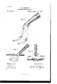
- Figure 1 represents the spiking-fork in perspective.
- A is the fulcrum-point; H, the point of contact with the rail.
- B B are the rockerprongs of the fork intended to go under the tie.
- O is the handle, forming a sleeve or socket,
- Fig. 2 represents the fork in use.
- D is a cross-tie, end View;
- E the rail in position for spiking to tie;
- F the spike for fastening same.
- the power applied by means of handle G holds the tie and rail closely together and enables the driving of the spike F rapidly, accurately, and without injury to road-bed, rail, or tie, or if the rail is to be cut, holds same firmly while being cut.
- Fig. 3 is a front sectional view of the fork, showing how same straddles the rail.
- the spiking-fork consists of a device made, preferably, of steel, having two prongs of sufiicient length to pass under the tie or timber to which the rail is to be fastened and extend upward at a slight angle to a height slightly greater than the thickness of the tie and the height of the rail, the tines gradually approaching each other and joining at the ful crum-point of the fork.
- the shank or handle extends backward at an angle of twenty to thirty degrees and is formed into a sleeve or socket, into which the wooden handle is fitted, or, if preferred, the entire handle or shaft may be of metal, in either instance length of same being appropriate to work required.
- the point of union of the tines of the fork is wide enough to freely straddle the rail.
- the point of contact with the rail is flat transversely and slightly curved or convexed longitudinally, the fulcrum being strongly reinforced, all of which is substantially shown in the accompanying drawings.
- I claim this is the only tool which can be worked parallel with the rail, enabling its use in cuts, tunnels, embankments, and crowded yards.
- I claim the most effective tie-raiser for leveling or for spiking being complete in itself, self-adjusting, dispensing with all chunks, blocks, pry-poles, and other devices for raising or supporting the tie while leveling or spiking.
- the improved spiking-fork herein described comprising the handle or stem, the fulcrum-point and the curved rocker-prongs adapted to straddle the rail and pass completely under and embrace the tie, whereby the tie and rail are clamped together for spikmg.
Landscapes
- Engineering & Computer Science (AREA)
- Architecture (AREA)
- Civil Engineering (AREA)
- Structural Engineering (AREA)
- Machines For Laying And Maintaining Railways (AREA)
Description
(No Model.)
J. Q. MYERS. RAILROAD SPIKING FORK.
No. 580,418. PatentdApr. 13, 1897.
fia
llnrrnn @TATE PATENT JOHN Q. MYERS, OF ORLANDO, FLORIDA.
RAILROAD SPIKING-FORK.
SPECIFIGATION forming part of Letters Patent No. 580,418, dated April 13, 1897. Application filed December 23, 1895. Serial No. 573,021. (No model.)
To all whom it may concern.-
Be it known thatI, JOHN Q. MYERS, a citizen of the United States, residing at Orlando, in the county of Orange and State of Florida, have invented a new and useful Railroad Spiking-Fork, of which the following is a specification.
The objects of my invention are, first, to facilitate the spiking of rails to cross-ties in construction and repair of railroad-tracks or any track using rails and ties by supporting and leveling the tie, bringing and holding the rail and tie in close contact, furnishing a firm resistance to the strokes of the hammer driving the spike, thereby making the work more accurate and secure, preserving the trackbed, and avoiding expensive releveling up of track; second, to hold bars or rails of iron, steel, or other material firmlyin position while being cut or sawed. I attain these objects by the device illustrated in the accompanying drawings.
Figure 1 represents the spiking-fork in perspective. A is the fulcrum-point; H, the point of contact with the rail. B B are the rockerprongs of the fork intended to go under the tie. O is the handle, forming a sleeve or socket,
into which a strong wooden extension-handle is to be inserted, the power being proportioned to the leverage or length of the said handle.
Fig. 2 represents the fork in use. D is a cross-tie, end View; E, the rail in position for spiking to tie; F, the spike for fastening same. The power applied by means of handle G holds the tie and rail closely together and enables the driving of the spike F rapidly, accurately, and without injury to road-bed, rail, or tie, or if the rail is to be cut, holds same firmly while being cut.
Fig. 3 is a front sectional view of the fork, showing how same straddles the rail.
The spiking-fork consists of a device made, preferably, of steel, having two prongs of sufiicient length to pass under the tie or timber to which the rail is to be fastened and extend upward at a slight angle to a height slightly greater than the thickness of the tie and the height of the rail, the tines gradually approaching each other and joining at the ful crum-point of the fork. The shank or handle extends backward at an angle of twenty to thirty degrees and is formed into a sleeve or socket, into which the wooden handle is fitted, or, if preferred, the entire handle or shaft may be of metal, in either instance length of same being appropriate to work required. The point of union of the tines of the fork is wide enough to freely straddle the rail. The point of contact with the rail is flat transversely and slightly curved or convexed longitudinally, the fulcrum being strongly reinforced, all of which is substantially shown in the accompanying drawings.
I claim this is the only tool which can be worked parallel with the rail, enabling its use in cuts, tunnels, embankments, and crowded yards. I claim the most effective tie-raiser for leveling or for spiking, being complete in itself, self-adjusting, dispensing with all chunks, blocks, pry-poles, and other devices for raising or supporting the tie while leveling or spiking. I claim the most accurate tool for giving level base to tie, insuring accuracy and security in spiking, the most economical and the most effective device for holding rails While being cut for purposes of construction or repair.
What I claim as my invention, and desire to secure by Letters Patent, is-
1. The improved spiking-fork herein described comprising the handle or stem, the fulcrum-point and the curved rocker-prongs adapted to straddle the rail and pass completely under and embrace the tie, whereby the tie and rail are clamped together for spikmg.
2. In a spiking-fork, the combination of the stem, the rocker-prongs adapted to straddle the rail and engage beneath thetie, and the reinforcement at the fulcrum or meeting point of the stem and prongs as set forth.
J. EDWARD ALLEN, JOSEPH H. J ones.
Publications (1)
| Publication Number | Publication Date |
|---|---|
| US580418A true US580418A (en) | 1897-04-13 |
Family
ID=2649096
Family Applications (1)
| Application Number | Title | Priority Date | Filing Date |
|---|---|---|---|
| US580418D Expired - Lifetime US580418A (en) | Railroad spiking-fork |
Country Status (1)
| Country | Link |
|---|---|
| US (1) | US580418A (en) |
Cited By (1)
| Publication number | Priority date | Publication date | Assignee | Title |
|---|---|---|---|---|
| US2837313A (en) * | 1955-06-20 | 1958-06-03 | Frank J Rogowski | Safety railroad tie holder |
-
0
- US US580418D patent/US580418A/en not_active Expired - Lifetime
Cited By (1)
| Publication number | Priority date | Publication date | Assignee | Title |
|---|---|---|---|---|
| US2837313A (en) * | 1955-06-20 | 1958-06-03 | Frank J Rogowski | Safety railroad tie holder |
Similar Documents
| Publication | Publication Date | Title |
|---|---|---|
| US580418A (en) | Railroad spiking-fork | |
| US802588A (en) | Lifting-jack. | |
| US1030896A (en) | Tie and rail-fastener. | |
| US571064A (en) | Third to ferd todd | |
| US262384A (en) | Tubular railroad-rail | |
| US569552A (en) | Spike-extractor and railway-tie lifter | |
| US152469A (en) | Improvement in railway-tracks | |
| US1285380A (en) | Rail-fastening means. | |
| US620953A (en) | Rail-tie | |
| US425526A (en) | Spike-puller | |
| US732424A (en) | Tie-plate. | |
| US964726A (en) | Rail-fastening. | |
| US455337A (en) | Manufacture of railroad-ties | |
| US421268A (en) | Railroad-rail brace | |
| US767878A (en) | Railway cross-tie and clamp. | |
| US803775A (en) | Railroad-tie. | |
| US438764A (en) | Metal railroad-tie | |
| US580998A (en) | Spiking-bar | |
| US443274A (en) | Rail-fastening device | |
| US777253A (en) | Railway-tie plate. | |
| US942650A (en) | Railroad-tie. | |
| US249407A (en) | seevis | |
| US657295A (en) | Device for preventing creeping of rails. | |
| US387602A (en) | Petee semonin | |
| US960398A (en) | Tie-spacing jack. |