US5802438A - Method for generating a crystalline 99 MoO3 product and the isolation 99m Tc compositions therefrom - Google Patents
Method for generating a crystalline 99 MoO3 product and the isolation 99m Tc compositions therefrom Download PDFInfo
- Publication number
- US5802438A US5802438A US08/801,981 US80198197A US5802438A US 5802438 A US5802438 A US 5802438A US 80198197 A US80198197 A US 80198197A US 5802438 A US5802438 A US 5802438A
- Authority
- US
- United States
- Prior art keywords
- vaporized
- moo
- crystals
- tco
- heating
- Prior art date
- Legal status (The legal status is an assumption and is not a legal conclusion. Google has not performed a legal analysis and makes no representation as to the accuracy of the status listed.)
- Expired - Lifetime
Links
Images
Classifications
-
- G—PHYSICS
- G21—NUCLEAR PHYSICS; NUCLEAR ENGINEERING
- G21G—CONVERSION OF CHEMICAL ELEMENTS; RADIOACTIVE SOURCES
- G21G1/00—Arrangements for converting chemical elements by electromagnetic radiation, corpuscular radiation or particle bombardment, e.g. producing radioactive isotopes
- G21G1/04—Arrangements for converting chemical elements by electromagnetic radiation, corpuscular radiation or particle bombardment, e.g. producing radioactive isotopes outside nuclear reactors or particle accelerators
- G21G1/12—Arrangements for converting chemical elements by electromagnetic radiation, corpuscular radiation or particle bombardment, e.g. producing radioactive isotopes outside nuclear reactors or particle accelerators by electromagnetic irradiation, e.g. with gamma or X-rays
Definitions
- the present invention generally relates to the production of 99m Tc and related compositions, and more particularly to the production of a specialized crystalline 99 MoO 3 composition and a sublimation process for isolating 99m Tc compositions therefrom.
- 99m Tc compositions (which shall collectively include both elemental 99m Tc and 99m Tc-containing compounds) are currently being used in 80-90% of all nuclear medical imaging procedures in the United States. These procedures are employed for many different purposes including cancer detection. At the present time, more than 10 million 99m Tc scans are conducted in the United States per year. Likewise, the use of 99m Tc compositions for medical imaging purposes has steadily increased over the past twenty years. From a commercial standpoint, there are over two dozen 99m Tc-based drug products which have been approved by the U.S. Food and Drug Administration (hereinafter "FDA"). These compositions are used to analyze the following tissue materials: bone, liver, lung, brain, heart, kidney, and other organs as discussed in Wagner, H.
- FDA U.S. Food and Drug Administration
- 99m Tc compositions have continued to make steady inroads on established radioisotope products including 201 Tl for cardiac analysis and 75 Se for brain, liver and kidney imaging. It is therefore anticipated that the demand for 99m Tc medical products will grow steadily (e.g. by at least about 5% per year) over the next decade or more.
- 99m Tc compositions have many beneficial characteristics when used in nuclear imaging processes. These characteristics are discussed in numerous references, including Saha, G. B., Fundamentals of Nuclear Pharmacy, Third Ed., New York, pp. 65-79, Springer-Verlag (1992). For example, 99m Tc has a six hour half-life which is important from a safety and compatibility perspective when human subjects are involved. Furthermore, 99m Tc emits a substantial amount of 141 keV gamma radiation with very little particulate emission (e.g. in the form of conversion electrons). This gamma energy level is useful since it can exit the human body from deep organs (e.g. the heart), yet is not too high to collimate effectively in modern gamma camera units.
- the 99 Mo parent of 99m Tc has a half-life which is about ten times that of 99m Tc. This relationship facilitates the development of a radionuclide generator that produces high yields of easily-separated 99m Tc compositions.
- 99m Tc compositions are also useful in many chemically-induced radiolabelling reactions, including the formation of chelates from reduced technetium or from ligand exchange processes. Accordingly, 99m Tc compositions have many different characteristics which are of considerable value in medical imaging applications.
- the "m" in 99m Tc signifies the metastable excited state of the technetium isotope whose atomic weight is 99. This metastable state has the aforementioned half life of six hours, and is a medically useful radioisotope of technetium. This is distinct from the ground state of the same isotope 99 Tc which has no medical usefulness.
- 99 Tc is also radioactive but has a half life of about 213,000 years.
- the 99 Mo produced using this approach (which is characterized as "activation moly") is generally limited to a low specific activity level of about 2 Ci/g.
- the photons or bremsstrahlung will need to exceed the threshold energy for the 8.3MeV photoneutron reaction listed in equation (4) which involves 100 Mo( ⁇ ,n) 99 Mo.
- bremsstrahlung having energy levels above 10.6 MeV may likewise induce the secondary reactions set forth in equations (5) and (6) which involve 100 Mo( ⁇ ,p) 99 Nb and 100 Mo( ⁇ ,p) 99m Nb. Both of these reactions produce products which beta-decay to 99 Mo very quickly as outlined above. If the bremsstrahlung are at other energy levels (e.g. in the range of 14-20 MeV), they can induce double neutron or proton emission. However, these reactions both produce stable 98 Mo and do not generate significant amounts of impurities.
- the use of particle accelerator technology to manufacture 99 Mo provides many benefits compared with conventional reactor systems using high enriched uranium. These benefits include reduced operating costs, improved safety, and the avoidance of long-term nuclear waste generation.
- a need remains for an effective and rapid procedure for separating the desired 99m Tc daughter compositions from the 99 Mo parent.
- many different methods have been employed to separate 99m Tc compositions from 99 Mo products. Some of these processes use multi-step chemical procedures which are cost intensive and of limited effectiveness. For example, in situations involving the reactor-based generation of "fission moly" (e.g.
- the resulting 99 Mo product is processed using chromatographic techniques to isolate the desired 99m Tc compositions. Specifically, the fission product is treated using an alumina column in which molybdate ions ( 99 MoO 4 -2 ) are tightly bound to the column. Pertechnetate ions ( 99m TcO 4 -) generated from the radioactive decay of the parent compound are not bound and eluted using a saline solution.
- a filter at the end of the system which may be manufactured from numerous compositions including silica wool, nickel, and stainless steel.
- the filter must be maintained at a temperature of at least 310° C. which is above the boiling point of the vaporized 99m Tc composition, namely, 99m Tc 2 O 7 .
- the heated filter is specifically designed to trap considerable amounts of residual vaporized 99 MoO 3 compositions which are generated during the foregoing process. These materials, if not retained, will contaminate the final 99m Tc product.
- the gaseous composition which passes through the filter is then treated in an external condenser for recovery of the desired 99m Tc composition.
- this process is specifically designed for use with low specific activity reactor-produced 99 MoO 3 products.
- This situation exists because of the ease of irradiating a substantial mass of 98 MoO 3 in a reactor, combined with the fact that oxygen does not form any long-lived activation products under neutron irradiation.
- appreciable quantities of vaporized 99 MoO 3 are generated as undesired by-products in the foregoing procedure and conventional sublimation processes in general, 99m Tc recovery levels rarely exceed about 50%, along with decreased purity levels in the final product.
- the claimed treatment method represents a clear and substantial departure from prior processing methods. In particular, it substantially avoids the production of vaporized 99 MoO 3 by-products during the separation and isolation of desired 99m Tc materials.
- a need remains for a 99m Tc production method in which the parent nuclide ( 99 Mo) is manufactured in a cost-effective and safe manner without the generation of hazardous nuclear wastes, followed by efficient separation of the desired 99m Tc compositions from the parent with a high recovery level.
- a need likewise remains for a low-temperature 99m Tc production method in which the generation of undesired vaporized 99 MoO 3 is avoided so that maximum 99m Tc yields and purity levels are achieved. This need is especially important in view of the increased demand for 99m Tc compositions as previously noted.
- the current United States market for 99m Tc compositions is about $100,000,000 per year for deliveries of about 500 Ci per day of 99m Tc.
- the present invention satisfies this need in a highly effective manner which overcomes the problems and disadvantages described above.
- the claimed method optimizes the recovery process without the need for uranium-generated 99 Mo compositions or supplemental separation systems (e.g. filter units).
- the claimed invention therefore represents an advance in the art of 99m Tc recovery which provides the following benefits: (1) the production of substantial yields of 99m Tc in a low-temperature thermal isolation process without the corresponding generation of undesired vaporized 99 MoO 3 by-products; (2) the ability to produce substantial 99m Tc yields without using reactor-based uranium processes; (3) the isolation of 99m Tc compositions from 99 Mo products in a manner which avoids losses caused by incomplete separation of these materials; (4) generation of the desired 99m Tc compositions using a procedure which is cost effective, rapid, safe, and avoids the production of hazardous, long-term nuclear wastes; (5) the development of a method which uses a controlled condensation system to provide a high product purity level with a minimal number of operational steps; (6) the use of a simplified production system that does not require supplemental vapor filtration components and other sub-systems for the removal of waste 99 MoO 3 by-products; (7) the ability to manufacture desired 99m Tc compositions using a minimal amount of equipment;
- particle e.g. electron
- the present invention involves a unique and highly efficient method for producing, separating, and isolating 99m Tc compositions (e.g. 99m Tc and/or 99m Tc-containing compounds) from 99 Mo-containing materials (e.g. 99 MoO 3 ).
- the claimed process is characterized by a high level of separation efficiency which enables the production of a desired 99m Tc product in a rapid and effective manner.
- the present invention also uses a unique, crystalline 99 MoO 3 starting material which facilitates the production of 99m Tc compositions in a low temperature sublimation process which avoids the production of vaporized 99 MoO 3 during sublimation. As a result, a highly pure 99m Tc final product can be generated.
- an initial supply of 99 Mo metal is first provided.
- Production of the initial supply of 99 Mo metal may be accomplished in many ways, although a preferred and unique embodiment of the present invention involves the use of particle accelerator technology to generate this material.
- particle accelerator technology will be defined below and basically involves the use of a selected particle (e.g. electron) accelerator system to produce the desired starting materials.
- particle accelerator may encompass the use of both linear accelerator units as discussed further below and non-linear accelerator systems (e.g. conventional systems known as "racetrack” accelerators).
- the use of particle accelerator technology for this purpose avoids the need for expensive nuclear reactors and the long-term (e.g. long half-life) nuclear wastes associated therewith.
- a particle accelerator apparatus of standard design (optimally an electron-based linear accelerator) is provided which is supplied with a portion of enriched 100 Mo metal to be used as a target. Best results are achieved within an enrichment range of about 60-100%.
- the use of enriched l00 Mo for this purpose will enable the final 99m Tc product to be produced in the desired amounts, and will likewise assist in minimizing the generation of impurities. Further information regarding enrichment, the use of enriched 100 Mo metal, and the benefits it provides will be described below.
- the apparatus is activated in order to generate high energy photons (e.g. "bremsstrahlung") therein.
- the 100 Mo metal is then irradiated with the high energy photons to produce 99 Mo metal.
- the accelerator-generated 99 Mo metal is removed from the particle accelerator apparatus.
- 99 MoO 3 from the 99 Mo metal, it is dissolved in at least one oxygen-containing primary solvent (e.g. HNO 3 , H 2 SO 4 , or H 2 O 2 ) to generate a solvated 99 Mo product therefrom.
- the solvated 99 Mo product is thereafter dried (e.g. evaporated) in order to yield a dried 99 Mo compound in the form of a plurality of elongate 99 MoO 3 crystals.
- Many different methods may be used to evaporate the solvated 99 Mo product, and the present invention shall not be limited to any particular evaporation method for this purpose.
- the solvated 99 Mo product is heated at a temperature of about 250°-500° C.
- the resulting 99 MoO 3 crystals have a thin, elongate, and filamentous character with a substantial amount of exposed surface area which facilitates the evolution of 99m Tc compounds therefrom in a highly efficient manner during sublimation.
- 99 MoO 3 crystal formation in the manner described above produces a crystalline product in which 99m Tc species are effectively partitioned (e.g. segregated or precipitated on the crystal surface) from other non- 99m Tc components within the 99 MoO 3 crystals. Segregation in this manner greatly facilitates the complete evolution of 99m Tc compounds during sublimation without the co-production of vaporized 99 MoO 3 contaminants.
- reaction chambers and production systems may be employed to isolate the desired 99m Tc "daughter” product from its 99 MoO 3 "parent", with the claimed method not being limited to any specific manufacturing components.
- the claimed process will be performed in an elongate tubular reaction chamber having a first end, a second end, a side wall, and a passageway through the reaction chamber from the first end to the second end.
- the side wall of the reaction chamber will be seamless in order to avoid high temperature seals and eliminate undesired recesses or crevices which may trap the final 99m Tc product.
- the reaction chamber further includes (e.g.
- the heating section is divided into) a heating section beginning at the first end, heating means for applying heat to the heating section, an intermediate gas transfer section in fluid communication with the heating section, and a reaction product (e.g. 99m Tc) collecting section in fluid communication with the intermediate section.
- the collecting section is designed to condense and retain the desired 99m Tc reaction products therein.
- the collecting section terminates at the second end of the reaction chamber, with the intermediate section being positioned between the heating section and the reaction product collecting section.
- the reaction chamber is designed so that the collecting section at the second end of the chamber is positioned at about a 15°-165° angle (optimally about a 90° angle) relative to the intermediate section. This configuration avoids any undesired heat transfer from the heating and intermediate sections into the collecting section as further discussed below.
- the passageway through the reaction chamber will further include a 99 MoO 3 crystal containment vessel therein having an open top portion.
- the containment vessel is specifically positioned within the heating section.
- the containment vessel is preferably made of platinum or a platinum alloy.
- other construction materials which may be employed for this purpose include a Ni-Cr alloy, stainless steel, or quartz. These materials may be coated with an optional surface layer of platinum or gold if desired as determined by preliminary tests and discussed further below.
- the foregoing compositions (especially the platinum materials) are strong, resistant to physical deformation over a wide range of temperatures, and facilitate the heating (sublimation) process associated with the 99 MoO 3 crystals.
- the supply of 99 MoO 3 crystals is placed within the heating section in the reaction chamber (e.g. inside the containment vessel).
- the 99 MoO 3 crystals are then heated in the reaction chamber to a first temperature which is sufficiently high to sublimate the 99 MoO 3 crystals and generate a gaseous mixture which evolves therefrom comprising vaporized 99m TcO 3 and vaporized 99m TcO 2 .
- the first temperature will be sufficiently low to (1) avoid melting the 99 MoO 3 crystals; and (2) prevent the formation of vaporized 99 MoO 3 during the sublimation process.
- the above-listed goals are accomplished by using a first temperature of about 600°-775° C. which is achieved in the reaction chamber using the heating means.
- a first temperature of about 600°-775° C. which is achieved in the reaction chamber using the heating means.
- the specific temperature to be employed within this range will again be determined in accordance with preliminary pilot studies on the materials being processed and other factors, including the type of solvent which is used to generate the solvated 99 Mo product (discussed further below).
- the foregoing temperature level will cause a gaseous mixture to evolve from the 99 MoO 3 crystals during sublimation which consists of vaporized 99m TcO 3 and vaporized 99m TcO 2 .
- a small amount of vaporized 99m Tc 2 O 7 may also be produced.
- the amount of any vaporized 99m Tc 2 O 7 in the gaseous mixture will be so small that, for the sake of clarity and convenience, the gaseous mixture at this stage will be designated to only include vaporized 99m TcO 3 and vaporized 99m TcO 2 .
- the gaseous mixture is further characterized by the substantially complete absence of vaporized 99 MoO 3 in the mixture.
- the ability of the present invention to avoid the production of vaporized 99 MoO 3 during sublimation is primarily accomplished by (1) the use 99 MoO 3 in the form of elongate, high-surface-area crystals manufactured by the process described above in which the desired 99m Tc species are effectively partitioned in the crystals; and (2) heating of the 99 MoO 3 crystals at low, pre-melting temperatures.
- the vaporized 99m TcO 3 and vaporized 99m TcO 2 in the gaseous mixture are converted (e.g. oxidized) to a supply of vaporized 99m Tc 2 O 7 .
- Representative oxygen-containing oxidizing gases include but are not limited to O 2 (g), air, O 3 (g), H 2 O 2 (g), or NO 2 (g), with O 2 (g) providing best results.
- oxidizing gas (after pre-heating) is then introduced into the reaction chamber and passed over the 99 MoO 3 crystals at a preferred flow rate of about 10-100 std. cc/min during evolution of the gaseous mixture from the 99 MoO 3 crystals. Passage of the oxidizing gas over the heated 99 MoO 3 crystals in this manner forms a gaseous stream consisting of the oxidizing gas in combination with the gaseous mixture.
- the oxidizing gas oxidizes the vaporized 99m TcO 3 and vaporized 99m TcO 2 in the gaseous mixture to form a supply of vaporized 99m TC 2 O 7 from these components.
- the gaseous stream will contain vaporized 99m Tc 2 O 7 therein and remaining amounts of the oxidizing gas which are not consumed during oxidation of the vaporized 99m TcO 3 and vaporized 99m TcO 2
- the gaseous stream then passes through the heating section, the intermediate section (which functions as a gas transfer zone in which a certain degree of transitional cooling occurs) and enters the reaction product collecting section of the reaction chamber.
- This portion of the reaction chamber is characterized as the "collecting section" since final temperature levels are achieved therein which are sufficient to enable condensation (desublimation) of the vaporized 99m Tc 2 O 7 from the gaseous stream. In this manner, the final 99m Tc-containing reaction product can be isolated and collected as discussed further below.
- the gaseous stream As the gaseous stream passes through the intermediate section, it experiences a progressive decrease in temperature as the distance from the heating section increases. In particular, the gaseous stream typically experiences a reduction in temperature from about 600°-775° C. when the stream leaves the heating section and enters the intermediate section to a transitional temperature of about 300°-400 C. when the gaseous stream leaves the intermediate section.
- the gaseous stream (and the vaporized 99m Tc 2 O 7 therein) is cooled to a final temperature sufficient to condense and remove the vaporized 99m Tc 2 O 7 from the gaseous stream so that a condensed 99m Tc-containing reaction product is produced.
- Cooling and condensation of the vaporized 99m Tc 2 O 7 takes place within the reaction product collecting section of the reaction chamber.
- the collecting section of the chamber functions as a condensation stage in the claimed process.
- the gaseous stream is specifically cooled within the collecting section to a final temperature of about 20°-80° C. This step enables the vaporized 99m Tc 2 O 7 within the gaseous stream to be condensed and removed from the stream so that a condensed 99m Tc-containing reaction product is generated inside the collecting section.
- the condensed 99m Tc-containing reaction product is then collected (removed) from the collecting section and processed as desired in accordance with the intended use of the final 99m Tc product. Further information concerning the collection process will be discussed in greater detail below.
- a residual 99 MoO 3 -containing reaction product will typically remain within the heating section of the reaction chamber after the desired production cycle is completed.
- the 99m Tc isolation process described above is typically undertaken at discrete intervals or "milkings" to obtain specific on-demand quantities of the 99m Tc-containing reaction product. On-demand processing is undertaken since the 99m Tc-containing reaction product is subject to rapid decay and deterioration with a half-life of about six hours. For this reason, it is undesirable to generate excess amounts of the 99m Tc-containing reaction product which are not needed for immediate use.
- the residual 99 MoO 3 -containing reaction product which remains after system deactivation will normally contain significant amounts of 99m Tc compositions therein.
- the residual 99 MoO 3 -containing reaction product is reprocessed so that it can be used again when needed. Tests have shown that reprocessing of the residual 99 MoO 3 -containing reaction product as described below will provide maximum yields of the desired 99m Tc compositions compared with situations in which the reaction product is not reprocessed and simply reheated without removal from the sublimation system. Reprocessing is preferably accomplished by first collecting the residual 99 MoO 3 -containing reaction product from the heating section of the reaction chamber after deactivation of the system.
- the residual 99 MoO 3 -containing reaction product is dissolved in at least one secondary solvent to produce a dissolved 99 MoO 3 product.
- Representative compositions which may be employed as the secondary solvent include but are not limited to NH 4 OH or H 2 SO 4 .
- the dissolved 99 MoO 3 product is then dried (evaporated) to generate a supply of regenerated 99 MoO 3 crystals. Many different methods may be used to dry the dissolved 99 MoO 3 product, and the present invention shall not be limited to any particular evaporation method for this purpose.
- the dissolved 99 MoO 3 product is heated at a temperature of about 250°-500° C.
- the present invention represents a significant advance in the production and separation of 99m Tc compositions. High yields and purity levels are achieved in a manner which is clearly distinguishable from prior processes. As indicated below, the claimed invention involves many unique steps which provide numerous benefits ranging from improved separation efficiency and purity levels to a lack of long-term nuclear wastes.
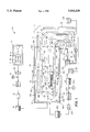
- FIG. 1 is a schematic representation (partially in cross-section) of an exemplary processing system which may be used in accordance with the methods of the present invention.
- the present invention involves a highly efficient method for producing purified 99m Tc compositions from 99 Mo starting materials (e.g. crystalline 99 MoO 3 ).
- 99 Mo starting materials e.g. crystalline 99 MoO 3
- This method is characterized by a number of significant benefits and advantages.
- the following description will involve preferred embodiments of the invention in which optimum operating parameters are disclosed.
- the claimed invention shall not be limited to the specific parameters provided below which are disclosed for example purposes. The most effective operating conditions for a given situation may be determined in accordance with routine preliminary pilot studies on the specific materials being processed and the equipment to be used for 99m Tc production.
- the initial step in the claimed process involves the generation of a 99 MoO 3 starting material which is ultimately treated to recover the desired 99m Tc compositions therefrom.
- Production of the 99 MoO 3 starting material is accomplished by the chemical conversion (e.g. oxidation) of a supply of 99 Mo metal into crystalline 99 MoO 3 as further discussed below.
- a 100 Mo metal target is irradiated with accelerated particles (e.g. electrons) using a particle accelerator apparatus.
- a "particle accelerator apparatus” basically consists of a particle accelerator unit which uses alternating voltages to accelerate electrons, protons, or heavy ions in a straight line.
- Representative particle (electron) accelerator systems may include a variety of different types ranging from a linear accelerator which accelerates particles in a straight line to a "racetrack" type system which accelerates particles in a circular or oval pathway.
- the present invention shall not be limited to the use of a particular particle accelerator system, although a linear electron accelerator is preferred.
- particle accelerator technology in the claimed methods is preferred, unique, and represents a significant development, other processes may also be employed to generate the initial supply of 99 Mo in this case including cyclotron-type (proton-based) methods. Accordingly, the present invention shall not be restricted to any particular methods for generating the requisite starting materials.
- FIG. 1 a system 10 which is suitable for use in accordance with the claimed invention is illustrated.
- a schematically-illustrated particle accelerator apparatus e.g. an electron-based linear accelerator
- FIG. 1 A schematically-illustrated particle accelerator apparatus (e.g. an electron-based linear accelerator) is shown in FIG. 1 at reference number 12.
- Particle accelerators are known in the art for producing various radioactive species, and many different linear and non-linear accelerator systems may be employed for the purposes set forth below. While the present invention shall not be limited to any particular accelerator apparatus as noted above, a representative system suitable for use as the particle accelerator 12 will consist of a 15 kW electron accelerator unit having an MeV rating of up to about 40 MeV. Such a system is commercially available from many sources including Varian Associates of Palo Alto Calif. (USA)-- model "Clinac 35"!.
- This system has an operational capability of 7 MeV-28 MeV, although in actual use, the system is operated at values of at least 10 MeV or more since about 10 MeV is the threshold energy level which is necessary in the photoneutron reactions of concern in the present invention.
- custom-manufactured electron accelerators having the foregoing capabilities may be obtained from Titan Beta Corporation of Dublin Calif. (USA). While accelerator systems having a lower maximum energy level can be employed to produce the desired materials in accordance with the invention, it is preferred that a particle accelerator 12 be selected which is capable of maintaining energy levels of at least about 20 MeV so that sufficient amounts of the 99 Mo starting materials can be generated.
- the particle accelerator 12 e.g. electron linear accelerator
- the particle accelerator 12 in the preferred embodiment of FIG. 1 delivers electrons (schematically illustrated in FIG. 1 at reference number 14) to a substantially circular high atomic number target member 16 which is about 0.5-5 mm thick, with a diameter of about 1-10 cm.
- target member 16 is constructed from tungsten, although other materials may also be employed for this purpose (e.g. tantalum).
- target members 16 with different dimensions e.g. thicknesses
- the electrons 14 strike the target member 16, they generate high energy photons or "bremsstrahlung” (schematically illustrated in FIG. 1 at reference number 20) which are then used to produce the desired 99 Mo metal product.
- the claimed process involves the separation of 99m Tc compositions (defined herein to encompass both 99m Tc and compounds thereof) from crystalline 99 MoO 3 .
- the crystalline 99 MoO 3 is manufactured in a unique manner which provides numerous benefits as discussed further below.
- FIG. 1 a preferred production method used to generate 99 MoO 3 crystals in accordance with the present invention is schematically illustrated.
- the starting material used to generate the desired 99 MoO 3 crystals consists of a 100 Mo-containing target 22 manufactured from 100 Mo metal. The use of 100 Mo metal for this purpose is preferred for many reasons.
- the use of 100 Mo metal is preferred because the reaction rate of high-energy photons ("bremsstrahlung") during the production of 99 Mo from 100 Mo will be considerably higher compared with processes which use 100 Mo compounds (e.g. 100 MoO 3 ) instead of 100 Mo metal.
- 100 Mo compounds e.g. 100 MoO 3
- 100 MoO 3 is employed as a starting material instead of 100 Mo metal since three oxygen atoms will compete with each atom of 100 Mo for interaction with the high energy photons. Interaction of the photons with oxygen atoms will generally reduce the energy of a given proportion of the photons over time to an energy level below the 8.3 MeV threshold value for the desired reaction.
- enriched 100 Mo metal is used in this embodiment to produce the 100 Mo-containing target 22.
- the terms "enriched” and “enrichment” as used herein involve a known process in which the isotopic ratio of a material is changed to increase the amount of a desired isotope in the composition.
- the natural abundance of 100 Mo is 9.63%. While this level will work in producing the desired 99m Tc products associated with the present invention, a greater level of enrichment is preferred in order to ensure that sufficient yields of the final 99m Tc compositions are generated. To achieve optimum results in this embodiment of the invention, an enrichment level of about 60-100% is desired.
- the production of enriched 100 Mo at these enrichment levels may be accomplished in many conventional ways.
- 100 Mo at about a 27% enrichment rate can be generated using standard nuclear fission processes in accordance with the following reaction: 235 U(n,f) 100 Mo.
- Other conventional methods for generating enriched 100 Mo at higher enrichment levels include (1) electromagnetic separation in a mass spectrometer or calutron; and (2) gaseous diffusion separation of MoF 6 .
- supplies of enriched 100 Mo at the foregoing enrichment levels may be obtained from government and commercial sources including the Isotope Production and Distribution Program at Oak Ridge National Laboratory of Oak Ridge, Tenn. (USA) and URENCO of Almelo, Netherlands.
- the use of enriched 100 Mo in the 100 Mo-containing target 22 assists in minimizing the production of undesired impurities.
- These impurities result from ( ⁇ ,n), ( ⁇ ,2n), ( ⁇ ,p), ( ⁇ ,2p), and ( ⁇ ,d) reactions involving other stable isotopes of Mo that may be present in the target 22.
- These are all nuclear reactions which exhibit a threshold energy, and can therefore be minimized by limiting the energy of the selected particle accelerator 12 while increasing its current at a given power output.
- the main radioimpurities which are produced from these reactions include radioactive isotopes of niobium, molybdenum and zirconium (e.g.
- Fission product molybdenum has neither 92 Mo or 94 Mo therein, and likewise includes about sixteen times less 96 Mo compared with natural molybdenum. The absence of 92 Mo and 94 Mo entirely eliminates over 50% of all the potential impurity-producing reactions. Likewise, low amounts of 96 Mo also substantially reduce the number of undesired side reactions.
- a preferred irradiation time associated with the target 22 produced from 100 Mo metal is about 24-48 hours using the representative accelerator systems described above. However, this parameter may be varied in accordance with numerous factors including the type of system being employed and its desired output. Irradiation times which are too short (generally less than about 24 hours) will increase the amount of 100 Mo metal required within the system 10, thereby resulting in additional operating costs. Likewise, irradiation times that are too long (generally more than about 48 hours) will produce a greater degree of quality variation and fluctuation in the average Ci output levels associated with the final 99m Tc product.
- a supply of 99 Mo metal (shown at reference number 24 in FIG. 1) is generated from the 100 Mo-containing target 22.
- the 99m Tc isolation process of the claimed invention involves the use of crystalline 99 MoO 3 as a starting material. Accordingly, the 99 Mo metal 24 must be converted into 99 MoO 3 in a rapid and efficient manner. To accomplish this, the accelerator-generated 99 Mo metal 24 is allowed to stabilize for a rest period of at least about one hour or more. During this stabilization period, low-level radioimpurities having a half-life of less than about several minutes will decay. This process assists in increasing the purity of the 99m Tc final product.
- the stabilized 99 Mo metal 24 is dissolved in at least one oxygen-containing primary solvent material 26 to generate a solvated (liquefied) 99 Mo product 30 schematically shown in FIG. 1.
- the primary solvent material 26 will consist of 6-9 M HNO 3 (optimally heated to a temperature exceeding about 70° C.).
- other compositions may be used for this purpose including but not limited to H 2 SO 4 (at a free acid concentration of 0.12 M heated to about 100°) or H 2 O 2 .
- the term "oxygen-containing" in connection with the solvent materials shall encompass the use of other solvent materials which do not directly contain oxygen as part of their molecular structure, but instead are in the from of an aqueous solution (e.g.
- the 99 Mo metal 24 will optimally be combined with the selected primary solvent material 26 in a metal 24 : primary solvent material 26 weight ratio of about 1-5 : 1-25. However, this ratio represents an exemplary embodiment which may be varied in accordance with preliminary pilot studies on the particular materials being processed.
- the solvated 99 Mo product 30 is then dried (evaporated) in a sealed oven apparatus 32 of conventional design at a temperature of about 250-500° C. for about 5-60 minutes. This process results in the formation of a dried 99 Mo compound consisting of a plurality of elongate, thin, and filamentous 99 MoO 3 crystals schematically illustrated in FIG. 1 at reference number 34. These crystals 34 are then used in the next stage of the 99m Tc production/isolation process.
- the thin, elongate, and needle-like characteristics of the 99 MoO 3 crystals 34 as described above provide numerous advantages and constitute an inventive aspect of primary importance.
- these characteristics result in a crystalline structure with a substantial amount of exposed surface area which facilitates the evolution of 99m Tc compounds therefrom in a highly efficient manner during sublimation.
- the thin, needle-like characteristics of the crystals 34 provide a shortened diffusion path for the release of volatile 99m Tc compounds compared with the use of pulverized 99 MoO 3 bulk materials.
- the presence of a shortened diffusion path, as well as the increased level of surface area enable the desired 99m Tc products to evolve in a more rapid and complete manner at lower, pre-melting temperatures.
- Lower operating temperatures provide an equally important benefit, namely, the ability to generate the desired final 99m Tc compositions while avoiding the production of undesired vaporized 99 MoO 3 which typically results when higher temperatures are employed.
- the production and low-temperature sublimation of crystalline 99 MoO 3 constitute unique aspects of the present invention which provide numerous benefits as outlined above.
- particle accelerator technology to generate the initial 99 Mo metal in the claimed process also represents a departure from conventional methods, especially those involving nuclear reactors which generate "fission moly".
- the use of a particle (e.g. electron) accelerator 12 at this stage in the system 10 reduces the costs, labor, and risks compared with reactor-produced (e.g. fission-generated) 99 Mo products.
- the present method avoids the generation of large amounts of long-term radioactive wastes.
- FIG. 1 This stage of the claimed process is schematically illustrated in FIG. 1. It specifically involves the separation and isolation of 99m Tc "daughter" compositions from the "parent” 99 MoO 3 crystals 34.
- the methods and procedures used to accomplish separation represent a substantial improvement over prior methods and enable the production of final 99m Tc products with high purity levels as discussed below.
- tubular reaction chamber 50 in which 99m Tc separation is accomplished. While many different configurations, dimensions, materials, and components may be used in connection with the reaction chamber 50, a representative and preferred chamber 50 will now be described.
- the term "tubular” as used herein shall generally signify an elongate structure having a bore or passageway therethrough surrounded by a continuous wall as discussed below. While the cross-sectional configuration of the reaction chamber 50 is preferably circular in order to facilitate the removal of desired materials from the internal regions of the chamber 50, numerous alternative cross-sectional configurations may be employed (e.g. square, rectangular, and the like).
- the reaction chamber 50 is preferably of single piece, seamless construction in order to avoid undesired recesses, crevices, and the like which can trap various reaction products and decrease product yields.
- construction materials used to manufacture the reaction chamber 50 many different compositions may be employed, with the present invention not being limited to any particular materials for this purpose.
- exemplary and preferred construction materials suitable for use in producing the reaction chamber 50 will consist of quartz, an alloy of Ni--Cr, or stainless steel.
- a optional protective layer of platinum or gold may be applied to the interior surfaces of the chamber 50 at a thickness of about 0.025-2.5 mm if desired as determined by preliminary tests in order to protect the chamber 50 from corrosion.
- any corrosion normally experienced from contact with 99 MoO 3 is eliminated by limiting the temperature of the 99 MoO 3 to below its melting point.
- the chamber 50 specifically includes an open first end 52, an open second end 54, and a continuous annular side wall 56.
- the side wall 56 is of seamless construction (as noted above) and has a preferred thickness "T 1 " (FIG. 1) of about 0.5-10 mm.
- the thickness "T 1 " of the side wall 56 will be uniform along the entire length of the reaction chamber 50 unless otherwise indicated or illustrated in FIG. 1.
- the side wall 56 also has an inner surface 60 and an outer surface 62 as shown in FIG. 1.
- the reaction chamber 50 Positioned within the reaction chamber 50 and entirely surrounded by the side wall 56 is an internal passageway 64 which extends continuously through the reaction chamber 50 from the first end 52 to the second end 54.
- the diameter values associated with the passageway 64 through the reaction chamber 50 will be discussed in further detail below.
- the reaction chamber 50 first includes a heating section 66 which begins at the first end 52 of the chamber 50 and ends at position 70 shown in FIG. 1.
- the heating section 66 will have a length "L 1 " (FIG.
- the diameter "D 1 " (FIG. 1) of the passageway 64 within the heating section 66 in an exemplary embodiment of the present invention will be about 1-10 cm which is sufficient to accommodate a containment vessel of variable size therein (discussed below) for retaining the initial supply of 99 MoO 3 crystals 34 within the reaction chamber 50.
- a heating system e.g. heating means
- the intermediate section 74 functions as a gas transfer stage in which gaseous materials in the system 10 (discussed in detail below) are transferred from the heating section 66 to the final sections of the system where the desired 99m Tc reaction products are isolated by condensation (desublimation).
- the intermediate section 74 also allows the gaseous materials in the system 10 to undergo a certain degree of transitional cooling. As described further below, the gaseous materials within the system 10 will experience a progressive decrease in temperature as they move away from the heating section 66 and through the intermediate section 74.
- the intermediate section 74 is in fluid communication with the heating section 66 as shown.
- the intermediate section 74 will have a length "L 2 "(FIG. 1) of about 10-100 cm from position 70 to position 72.
- the diameter "D 2 " (FIG. 1) of the passageway 64 within the intermediate section 74 will be about 1-10 cm in an exemplary and preferred embodiment.
- the intermediate section 74 is not being used to perform a direct separation (e.g. by condensation/desublimation) of any particular components in the gaseous materials travelling through the system 10, the length "L 2 " and diameter "D 2 " of the intermediate section 74 are not critical.
- the length "L 2 " and diameter "D 2 " of the intermediate section 74 will be selected in view of many considerations including the size of the system 10 and amount of transitional cooling which is desired prior to the final 99m Tc condensation stages. A greater degree of transitional cooling within the intermediate section 74 will enable a smaller (e.g. shorter) final condensation/collection section to be used at the second end 54 of the reaction chamber 50. Likewise, the need for a long intermediate section 74 may be diminished if a corresponding increase is made to the length or overall cooling capacity of the final collection (condensation) sections of the system 10. For this reason, the length "L 2 " and diameter “D 2 " of the intermediate section 74 may be varied as needed within the foregoing ranges in accordance with the desired operating characteristics and capabilities of the system 10.
- Reconfiguration of the final stages of the system 10 may involve appropriate size adjustments to the final sections of the reaction chamber 50 or the addition of auxiliary cooling systems at the second end 54 of the chamber 50 including chiller coils and the like.
- the present invention shall not be limited to any particular sizes, dimensions, and configurations in connection with the various sections of the reaction chamber 50, provided that the necessary sublimation and condensation processes (discussed below) are able to occur with a maximum degree of efficiency.
- the ranges listed above for "L 2 " and "D 2 " in connection with the intermediate section 74 represent preferred embodiments which will provide effective results in accordance with the operating procedures summarized below.
- the final section of the chamber 50 which consists of a reaction product collecting section 76.
- the collecting section 76 functions a main condensation stage in which sufficiently low temperatures are reached to enable condensation of the gaseous 99m Tc reaction products therein.
- the intermediate section 74 is positioned between the heating section 66 and reaction product collecting section 76 to complete the three-stage reaction chamber 50.
- the collecting section 76 is in fluid communication with the intermediate section 74 as illustrated.
- the collecting section 76 will have a length "L 3 " (FIG. 1) of about 1-100 cm from position 72 to the second end 54 of the reaction chamber 50.
- the operational capabilities of the collecting section 76 will be discussed further below.
- the diameter "D 3 " of the passageway 64 within the section 76 will be about 0.1-5 cm in a representative embodiment. However, these values may again be varied as needed in accordance with a variety of operational factors as determined by preliminary investigation.
- the point of transition between the intermediate section 74 and the reaction product collecting section 76 (e.g. at position 72) will involve a bevelled section 77 which is designed to avoid sharp angles within the passageway 64 so that the trapping of condensed reaction products is avoided.
- the transition between the sections 74, 76 is considered to take place at position 72 which is substantially in the middle of the bevelled section 77.
- the length values L 2 and L 3 associated with sections 74, 76 as shown in FIG. 1 are measured in a manner which takes into consideration the fact that the approximate transition point between the sections 74, 76 occurs at position 72 within the bevelled section 77.
- the reaction chamber 50 may be manufactured so that it is entirely linear (e.g. 180° ) with the first end 52 of the chamber 50 being in axial alignment with the second end 54.
- the reaction product collecting section 76 is positioned at an angle "X" of about 15°-165° (optimally about 90° as illustrated in FIG. 1) relative to the intermediate section 74 and heating section 66 (since the heating section 66 is in axial alignment with the intermediate section 74 in the embodiment of FIG. 1).
- the "line of sight" between the intermediate section 74 and the reaction product collecting section 76 is interrupted.
- This relationship is designed to create separate and distinct temperature gradients in sections 74, 76 of the chamber 50 so that condensation can occur in a rapid and complete manner within the collecting section 76 and not in upstream portions of the system 10.
- the carryover of thermal energy from earlier sections of the system 10 e.g. the heating section 66 and the intermediate section 74
- the size requirements associated with the collecting section 76 and the need for auxiliary cooling systems at the second end 54 of the reaction chamber 50 would correspondingly increase. It is therefore important to avoid the uncontrolled transfer of thermal energy (e.g. heat) from the heating section 66 and intermediate section 74 to downstream portions of the system 10 (e.g. the collecting section 76).
- This goal is accomplished in the embodiment of FIG. 1 by positioning the collecting section 76 at angle "X" relative to the intermediate section 74 as described above. In this manner, convective and radiant heat transfer from the heating section 66 and intermediate section 74 into the collecting section 76 is effectively avoided. The prevention of heat transfer using this approach will enable the reaction chamber 50 to function with a maximum degree of effectiveness.
- the heating section 66 is sized to receive the 99 MoO 3 crystals 34 therein which are subsequently processed (e.g. sublimated) as discussed below. Receipt (e.g. placement) of the 99 MoO 3 crystals 34 within the reaction chamber 50 may be accomplished using two different approaches. First, a cavity may be directly formed within the side wall 56 inside the reaction chamber 50, the outline of which is illustrated in dashed lines at reference number 90 in FIG. 1. However, in a preferred embodiment, an open containment vessel 92 shown cross-sectionally in FIG. 1 is positioned within the heating section 66 of the reaction chamber 50. The containment vessel 92 (also known as a "boat") is placed directly on the inner surface 60 of the side wall 56 at position 94 as illustrated.
- the containment vessel 92 also known as a "boat”
- the containment vessel 92 includes a closed bottom portion 96, upwardly-extending side portions 100, 102, and an open top portion 104. These components define an interior region 106 within the containment vessel 92 which is sized to receive the 99 MoO 3 crystals 34 therein.
- the 99 MoO 3 crystals 34 will be processed inside the containment vessel 92 in accordance with the specific sublimation procedures described below.
- the interior region 106 of the containment vessel 92 will have a depth "Y 1 " (FIG. 1) of about 1-50 mm, again depending on whether a small-scale laboratory system 10 or a large scale commercial system 10 is involved. In the system 10 shown in FIG.
- the interior region 106 of the containment vessel 92 will have a length of about 1-100 cm and a width of about 1-10 cm so that the interior region 106 has a total internal volume of about 0.1-5000 cm 3 .
- these values may be varied within the foregoing ranges as necessary in accordance with numerous factors including the desired size and capacity of the processing system 10.
- the containment vessel 92 is manufactured from a composition which facilitates even and complete heating of the 99 MoO 3 crystals 34 within the reaction chamber 50.
- the selected composition should also be sufficiently strong to accommodate the particular temperature changes experienced by the 99 MoO 3 crystals 34 in the system 10 during operation.
- Pt-Rh 90:10! Other construction materials which may be employed for this purpose include an alloy of Ni--Cr, stainless steel, or quartz.
- the vessel 92 may be coated with an optional surface layer of platinum or gold at an average thickness of about 0.025-2.5 mm in order to prevent corrosion.
- the containment vessel 92 will be manufactured from platinum or a platinum alloy, or will be coated with platinum as noted above, with the phrase "comprised of platinum” encompassing all of these variations.
- an additional aspect of the system 10 involves the use of an oxygen-containing oxidizing gas which is introduced into reaction chamber 50. While the function of the oxidizing gas will be described in further detail below, it is basically used to (1) move the desired gaseous (vaporized) reaction products through the system 10 for processing; and (2) convert various vaporized 99m Tc compositions (e.g.
- a supply of an oxygen-containing oxidizing gas 120 is provided which is retained within a storage container 122 of conventional design (e.g. made of steel or the like).
- representative oxygen-containing oxidizing gases 120 suitable for the purposes set forth herein will include O 2 (g), air, O 3 (g), H 2 O 2 (g) or NO 2 (g), with O 2 (g) being preferred because of its effectiveness and ease of use.
- the storage container 122 is operatively connected to a tubular gas flow conduit 124 having a first end 126 and a second end 130.
- the first end 126 is attached to the storage container 122, with the second end 130 being connected to a cylindrical gas delivery unit 132 which surrounds both the heating section 66 and at least a portion of the intermediate section 74 of the reaction chamber 50.
- a conventional pump 134 Positioned in-line within the gas flow conduit 124 is a conventional pump 134 (e.g. of a standard diaphragm type or other variety known and used for gas delivery). Alterna-tively, the pump 134 may be eliminated provided that the gas 120 is retained within the storage container 122 at a pressure level sufficient to ensure rapid and effective delivery of the gas 120 through the gas flow conduit 124 (e.g. about 1-3000 psi depending on the scale of the system 10).
- the gas flow conduit 124 may also have an optional in-line heater 135 therein which can be used to selectively heat the gas 120 during delivery if needed in accordance with preliminary pilot studies on the particular materials and system components being employed.
- the heater 135 may consist of any conventional (e.g. resistance-type) heater unit known in the art for the purposes set forth above. In-line heating using the heater 135 is designed to pre-heat the gas 120 to a temperature of about 20°-775° C. as it enters the gas delivery unit 132 so that optimum temperature levels may be maintained within the reaction chamber 50 while avoiding "cold spots".
- the gas delivery unit 132 (which is configured in the form of an enclosed cylindrical jacket) entirely encompasses the first end 52 of the reaction chamber 50, as well as the heating section 66 and all or part (at least 50-75%) of the intermediate section 74.
- the gas delivery unit 132 and its various components will be constructed from an inert, heat-resistant material (e.g. silica glass, quartz, or a selected metal such as stainless steel).
- the gas delivery unit 132 includes a continuous tubular side wall 140 which is preferably circular (annular) in cross-section with an inner surface 142 and an outer surface 144.
- the side wall 140 is sufficiently large to completely surround the heating section 66 and most of the intermediate section 74 of the reaction chamber 50. This size relationship enables the inner surface 142 of the side wall 140 to be spaced outwardly from the outer surface 62 of the reaction chamber 50 to create an annular gas flow zone 146 around the heating section 66 and intermediate section 74 as illustrated.
- the side wall 140 associated with the gas delivery unit 132 further includes a closed first end 150 and a closed second end 152.
- the first end 150 of the side wall 140 has an end plate 154 secured thereto (e.g. by welding or other conventional fastening method) in order to effectively seal the first end 150.
- the end plate 154 is manufactured from the same materials which are used to produce the other parts of the gas delivery unit 132 as discussed above. With continued reference to FIG. 1, the end plate 154 is spaced outwardly from the first end 52 of the reaction chamber 50 in order to form an open region 156 therebetween which functions as part of the gas flow zone 146 described above.
- the second end 152 of the side wall 140 includes an end plate 160 secured thereto.
- the end plate 160 is designed to effectively seal the second end 152 of the side wall 140 and is secured thereto by welding or other conventional fastening method.
- the end plate 160 is preferably manufactured from the same materials listed above in connection with the other components of the gas delivery unit 132.
- the end plate 160 further includes an opening 162 therein which is sized to allow the annular side wall 56 of the reaction chamber 50 to pass therethrough.
- the outer surface 62 of the reaction chamber 50 is sealed to and within the opening 162 of the end plate 160 by conventional sealing methods (e.g. o-rings, gaskets, and/or a screw-type thread system of standard design associated with the reaction chamber 50 and the opening 162).
- the second end 152 of the side wall 140 used in connection with the cylindrical gas delivery unit 132 further includes a bore 164 therethrough.
- the bore 164 is sized to receive the second end 130 of the gas flow conduit 124.
- the gas flow conduit 124 is operatively connected to the storage container 122 having the oxidizing gas 120 therein.
- the second end 130 of the conduit 124 is retained within the bore 164 by conventional attachment methods including adhesives, frictional engagement, and/or conventional mechanical fasteners. In this manner, gas 120 from the storage container 122 can be delivered at a rapid rate to the system 10.
- the specific design of the gas delivery unit 132 will enable the gas 120 to be supplied in a counter-current flow orientation.
- an alternative embodiment would involve direct attachment of the second end 130 of the gas flow conduit 124 to the first end 52 of the reaction chamber 50 using connection hardware known in the art for this purpose.
- the oxidizing gas 120 would then be delivered directly to the reaction chamber 50 without using the cylindrical gas delivery unit 132 described above.
- This embodiment would reduce the required amount of equipment in the system 10 and may be appropriate in various circumstances as determined by many factors including the type of system 10 under consideration, the desired scale of operation, and other related issues. Accordingly, the present invention shall not be restricted to any particular gas delivery method.
- the present invention shall not be restricted to any particular methods, components, or sub-systems which are used to provide the necessary degree of temperature control.
- the claimed method may involve many different procedures and sub-systems for achieving the desired temperature conditions within the heating section 66, intermediate section 74, and collecting section 76. Again, routine preliminary investigations may be employed to determine the heating and cooling systems which will provide optimum results in a given situation.
- FIG. 1 schematically illustrates various components which can be used to produce the desired thermal effects in the reaction chamber 50.
- the heating section 66 includes heating means 180 associated therewith.
- the heating means 180 will consist of a heater unit 182 positioned around the heating section 66 as illustrated.
- the heater unit 182 surrounds the outer surface 144 of the side wall 140 associated with the gas delivery unit 132. This particular arrangement of components not only heats the 99 MoO 3 crystals 34 within the heating section 66, but also maintains the incoming oxidizing gas 120 in the gas delivery unit 132 at stable and desired temperature levels of about 20°-775° C. (in cooperation with the heater 135 if necessary).
- the heater unit 182 would surround the outer surface 62 of reaction chamber 50 at the heating section 66.
- the heater unit 182 (which is schematically illustrated in FIG. 1) may involve many different systems which are known in the art for the general purposes set forth above.
- the heater unit 182 may consist of a single heating apparatus or a plurality of individual heating sub-systems with separate control units to achieve selective temperature adjustment at various positions on the heating section 66. Accordingly, the claimed invention shall not be limited to any particular type of heating system, provided that temperature levels of about 600°-775° C. (discussed further below) are maintained within the heating section 66 so that the 99 MoO 3 crystals 34 can be sublimated as discussed below.
- the heater unit 182 will specifically consist of a conventional tube furnace assembly or selected heating elements (e.g. nichrome wires) wrapped around the outer surface 144 of the gas delivery unit 132 or around the outer surface 62 of the reaction chamber 50 if a gas delivery unit 132 is not employed.
- selected heating elements e.g. nichrome wires
- the temperature of the gas 120 will be much less than the temperature levels within the intermediate section 74, depending on the level of heating provided by the heater 135 (which may be used to heat the incoming gas 120 to a temperature within a broad range as noted above.) Further information on the desired temperature characteristics in the intermediate section 74 will be discussed below.
- cooling is preferably provided by direct contact of the collecting section 76 with ambient air.
- the collecting section 76 in the embodiment of FIG. 1 is uncovered and exposed so that the outer surface 62 of the reaction chamber 50 at the collecting section 76 can come in contact with air at "room temperature” levels (e.g. about 20°-25° C.).
- room temperature e.g. about 20°-25° C.
- auxiliary cooling units are not a requirement in system 10, they may be needed to achieve a desired level of efficiency as determined by preliminary experimentation involving many factors including the size of the selected reaction chamber 50, the materials being processed, the ambient environmental conditions (temperatures) experienced by the system 10, and other factors. Accordingly, the present invention shall not be limited to any particular heating/cooling systems, provided that the necessary temperature gradients are achieved in the system 10 as discussed below.
- the initial supply of 99MoO 3 crystals 34 (manufactured as described above) is placed within the containment vessel 92 in the heating section 66 of the reaction chamber 50.
- the 99 MoO 3 crystals 34 are placed within the cavity.
- the 99 MoO 3 crystals 34 are heated in the heating section 66 of the reaction chamber 50 to a first temperature which is sufficient to sublimate the crystals 34 but sufficiently low to (1) avoid melting the crystals 34; and (2) avoid forming vaporized 99 MoO 3 .
- the first temperature may be any temperature which is less than the melting point of the 99 MoO 3 crystals 34 but is nonetheless high enough to sublimate the crystals 34.
- the gaseous mixture 190 will include the following components in combination: (1) vaporized 99m TcO 3 ; and (2) vaporized 99m TcO 2 . A small amount of vaporized 99m Tc 2 O 7 may also be produced.
- the amount of any vaporized 99m Tc 2 O 7 in the gaseous mixture 190 will be so small that, for the sake of clarity and convenience, the gaseous mixture 190 at this stage will be designated to only include vaporized 99m TcO 3 and vaporized 99m TcO 2 .
- the gaseous mixture 190 will be approximately +99% free from vaporized 99 MoO 3 which, for the purposes of this invention, justifies characterization of the gaseous mixture 190 as lacking any contaminating amounts of vaporized 99 MoO 3 therein.
- the unique structure associated with the 99 MoO 3 crystals 34 provides many benefits, including a lack of vaporized 99 MoO 3 in the gaseous mixture 190 as noted above.
- the thin, needle-like character of the crystals 34 creates a substantial amount of exposed surface area which facilitates the evolution of 99m Tc compounds therefrom in a highly efficient manner during sublimation.
- the thin and elongate character of the crystals 34 provides a shortened diffusion path for release of the volatile 99m Tc compounds compared with the use of non-crystalline 99 MoO 3 granular materials. The presence of a shortened diffusion path in the crystals 34, as well as the increased level of surface area, enable the desired 99m Tc compositions (e.g.
- vaporized 99m TcO 3 and vaporized 99m TcO 2 to evolve in a more rapid and complete manner at lower (sub-melting) temperatures.
- Lower operating temperatures provide an equally important benefit, namely, the ability to generate the desired final 99m Tc compositions while avoiding the production of undesired vaporized 99 MoO 3 which typically results when higher temperatures are employed.
- the presence of vaporized 99 MoO 3 will contaminate the final 99m Tc product unless the 99 MoO 3 is removed from the processing system using additional steps and procedures (e.g. additional condensation stages). These supplemental stages can increase the cost and complexity of the production system.
- Heating of the 99 MoO 3 crystals 34 will occur in a thorough and consistent manner within the containment vessel 92 as previously discussed.
- the selection of a containment vessel 92 manufactured from the materials listed above (particularly platinum) will ensure that the 99 MoO 3 crystals 34 are evenly heated.
- the use of a containment vessel 92 made from the foregoing materials (particularly platinum) also prevents the vessel 92 from changing shape at the temperature levels encountered within the heating section 66. As a result, the bottom portion 96 of the vessel 92 will remain substantially flat so that even heating is ensured.
- a containment vessel 92 made of these materials will likewise avoid breakage problems when the 99 MoO 3 crystals 34 in the vessel 92 undergo substantial temperature changes during deactivation of the system 10.
- the heating process described above is typically allowed to continue for a time period of about 0.1-2 hours, although the exact heating time will depend on the type of heating means 180 being employed and the amount of 99 MoO 3 crystals 34 within the system 10.
- the oxidizing gas 120 e.g. O 2 (g)
- the oxidizing gas 120 is designed to convert the vaporized 99m TcO 3 and vaporized 99m TcO 2 to a supply of vaporized 99m Tc 2 O 7 as discussed further below.
- the supply of oxidizing gas 120 is delivered from the storage container 122 through the gas flow conduit 124 using the pump 134.
- the gas 120 is sufficiently pressurized as noted above, release of the gas 120 from the container 122 will cause it to spontaneously pass through the gas flow conduit 124 in a similar manner without using the pump 134.
- the gas 120 will then flow from the conduit 124 into the cylindrical gas delivery unit 132. Specifically, the gas 120 will enter the gas delivery unit 132 through the bore 164 (FIG. 1) and thereafter pass into the annular gas flow zone 146 surrounded by the side wall 140. As the gas 120 continues to enter the gas delivery unit 132, it will flow in the direction of arrows 192 and simultaneously pass over the outer surface 62 of the reaction chamber 50 at the intermediate section 74 in order to provide a temperature modulating effect (discussed further below).
- the gas 120 will then pass through the open region 156 between the end plate 154 and the first end 52 of the reaction chamber 50, followed by entry into the first end 52 in the direction of arrow 194.
- the gas 120 will flow into and through the reaction chamber 50 at a flow rate of about 10-100 std. cc/min which may be achieved by proper adjustment of the gas pump 134 or other conventional gas flow regulators (not shown).
- this flow rate will be applicable in alternative variations of the system 10 which do not use the gas delivery unit 132 and instead directly introduce the gas 120 into the open first end 52 of the reaction chamber 50 as discussed above.
- the actual gas flow rate in a given situation will depend on a variety of factors including the size of the system 10, the materials being processed, and other considerations.
- delivery of the gas 120 may be undertaken immediately before or simultaneously with sublimation of the 99 MoO 3 crystals 34.
- the gas 120 is optimally delivered into the reaction chamber 50 at a temperature of about 20°-775° C. which is achieved prior to passage over the 99 MoO 3 crystals 34 using the heating means 180 which surrounds the gas delivery unit 132 in cooperation with the heater 135 if necessary.
- the gas 120 e.g. O 2 (g)
- the heating section 66 As the gas 120 (e.g. O 2 (g)) passes into and through the heating section 66, it combines with the gaseous mixture 190 to form a gaseous stream 196 schematically illustrated in FIG. 1.
- the gas 120 oxidizes the vaporized 99m TcO 3 and vaporized 99m TcO 2 in the gaseous mixture 190 to form a supply of vaporized 99m Tc 2 O 7 therefrom as previously noted.
- the gaseous stream 196 at this stage will consist of the following materials in combination: (1) remaining (unreacted) amounts of the gas 120 (e.g. O 2 (g)); and (2) vaporized 99m Tc 2 O 7 .
- excess amounts of the gas 120 will be used in the system 10 above the amount necessary to perform an oxidizing function so that the gas 120 can also be used as a continuous carrier to move the various vaporized materials through the system 10. For this reason, excess amounts of unreacted gas 120 will, in most cases, be present in the gaseous stream 196.
- the gaseous stream 196 then passes out of the heating section 66 at approximately the same flow rate associated with the initial entry of the oxidizing gas 120 into the reaction chamber 50, and thereafter enters the intermediate section 74.
- the intermediate section 74 begins at position 70 and ends at position 72 illustrated in FIG. 1.
- the intermediate section 74 (which may be of variable length as indicated above) is designed for use as a gas transfer zone in which a certain degree of preliminary transitional cooling takes place prior to main cooling (condensation) in the collecting section 76.
- the gaseous stream 196 As the gaseous stream 196 enters the intermediate section 74 in the specific embodiment of FIG. 1, it is subjected to a gradual, transitional cooling process which will correspondingly reduce the degree of cooling (e.g. the amount of temperature drop) which is ultimately needed for condensation in the collecting section 76. This is accomplished by the formation of a specific negative temperature gradient along the length of the intermediate section 74, with the gaseous stream 196 experiencing a gradual decrease in temperature while it moves through the section 74. When the gaseous stream 196 enters the intermediate section 74, it will have an initial temperature of about 600°-775° C. in a representative embodiment as it passes position 70 shown in FIG. 1. A gradual and progressive decrease in the temperature of the gaseous stream 196 will then take place in the intermediate section 74.
- the gaseous stream 196 in the intermediate section 74 is cooled from the initial temperature of about 600°-775° C. at position 70 to a transitional temperature of about 300°-400° C. when the stream 196 exits the intermediate section 74 at position 72.
- optimum results will be achieved if the temperature decrease associated with the gaseous stream 196 is undertaken at a cooling rate of about 5°-50° C./cm within the intermediate section 74.
- the term "cooling rate" as used herein shall involve the amount of cooling (in °C.) per unit length of the section under consideration. This is accomplished by the control of numerous factors including the length L 2 of the intermediate section 74 which (as noted above) is optimally about 1-100 cm, depending on the desired scale of the system 10.
- the cooling rate in the intermediate section 74 may be controlled by the counter-current flow of gas 120 through the gas delivery unit 132 along the outer surface 62 of the reaction chamber 50.
- the length "L 2 " and diameter “D 2 " of the intermediate section 74 are not critical.
- the length "L 2 " and diameter “D 2 " of the intermediate section 74 will be selected in accordance with many considerations including the size of the system 10 and amount of transitional cooling which is desired prior to the final 99m Tc condensation stages. A greater degree of transitional cooling which occurs within the intermediate section 74 will enable a smaller (e.g. shorter) final collecting section 76 to be used as discussed above.
- the length “L 2 " and diameter “D 2 " of the intermediate section 74 may be varied as needed in accordance with the desired structural configuration of the system 10 which depends on numerous economic and operational factors.
- the intermediate section 74 it is also possible for the intermediate section 74 to be eliminated entirely, provided that the final cooling/condensation stages of the system 10 (e.g. the collecting section 76) are reconfigured to enable rapid and complete cooling of the gaseous materials in the system 10 to condensation levels. Reconfiguration of the final stages of the system 10 may involve increases in the size (length and/or diameter) of the collecting section 76 or the addition of chiller coils and other auxiliary cooling systems at the second end 54 of the reaction chamber 50.
- the present invention shall be not limited to any particular sizes, dimensions, and configurations in connection with the various sections of the reaction chamber 50, provided that the necessary sublimation and condensation processes are able to occur with a maximum degree of effectiveness.
- the gaseous stream 196 leaves the intermediate section 74 at position 72 (FIG. 1), it will remain unchanged from a chemical standpoint, and will again contain the following compositions in combination: (1) remaining (unreacted) amounts of the oxidizing gas 120 (e.g. O 2 (g)); and (2) vaporized 99m Tc 2 O 7 .
- the gaseous stream 196 enters the reaction product collecting section 76 of the reaction chamber 50 as it passes position 72 (FIG. 1).
- the collecting section 76 functions as the main cooling/condensation stage in the system 10.
- the gaseous stream 196 is then condensed within the collecting section 76 to remove the vaporized 99m Tc 2 O 7 from the stream 196.
- the gaseous stream 196 As the gaseous stream 196 enters the collecting section 76, it will have a starting temperature of about 300°-400° C. in the specific embodiment of FIG. 1 (which is substantially the same as the transitional temperature of the gaseous stream 196 when it left the intermediate section 74). However, as previously noted, the starting temperature of the gaseous stream 196 as it enters the collecting section 76 will vary depending on the size characteristics of the other parts of the system 10 (e.g. the intermediate section 74) which may be adjusted as desired.
- the gaseous stream 196 is then cooled to a final or ending temperature of about 20°-80° C as it passes through and leaves the collecting section 76 at the second end 54 of the reaction chamber 50.
- This temperature decrease will occur in a gradual and progressive manner in order to ensure maximum yields of the desired 99m Tc final product. Optimum results will be achieved if the temperature decrease associated with the gaseous stream 196 in the collecting section 76 is undertaken at a cooling rate of about 4°-200° C./cm therein depending on the size and desired scale of the system 10 as again determined by preliminary investigation. It should also be noted that the flow rate associated with the gaseous stream 196 at this stage will remain constant at the values listed above. In this regard, the flow rate of the gaseous stream 196 through all parts of the reaction chamber 50 will, in a preferred embodiment, be the same (e.g. at about 10-100 std. cc/min as previously noted).
- Cooling of the gaseous stream 196 within the reaction product collecting section 76 is primarily accomplished by controlling the length L 3 of the collecting section 76 as discussed above.
- the collecting section 76 is cooled by direct contact with ambient air (which will have a temperature of about 20 °-25° C. in typical processing environments.)
- ambient air which will have a temperature of about 20 °-25° C. in typical processing environments.
- ambient air which will have a temperature of about 20 °-25° C. in typical processing environments.
- ambient air which will have a temperature of about 20 °-25° C. in typical processing environments.
- ambient air which will have a temperature of about 20 °-25° C. in typical processing environments.
- ambient air which will have a temperature of about 20 °-25° C. in typical processing environments.
- auxiliary cooling systems may be used if appropriate as determined by preliminary pilot studies involving many factors including the size of the system 10 being employed, as well as the environmental conditions associated with the process.
- any method by which the temperature of the gaseous stream 196 is reduced to a final value within the range set forth above may be employed within the scope of the invention.
- the condensation and removal of vaporized 99m Tc 2 O 7 from the gaseous stream 196 is accomplished within the collecting section 76 by control of the following factors: (1) decreasing the temperature of the gaseous stream 196 from the starting value listed above to the designated ending value; (2) the use of a collecting section 76 having a length L 3 within the above-described range; and (3) cooling of the gaseous stream 196 at the foregoing rate. All of these factors enable vaporized 99m Tc 2 O 7 in the gaseous stream 196 to be condensed in a highly effective manner.
- a solid, adherent 99m Tc 2 O 7 film 202 (FIG. 1) will collect on the inner surface 60 of the reaction chamber 50 in the collecting section 76. While formation of the 99m Tc 2 O 7 film 202 will typically occur by condensation, other processes may also be taking place within the collecting section 76 in connection with the formation of film 202. For example, one of these other processes may involve adsorption on the inner surfaces of the collecting section 76. In this regard, the exact processes which take place within the collecting section 76 are not completely known at the present time. However, since it is currently understood that condensation is the primary physical process which occurs within the collecting section 76, the term “condensation" shall be used herein to collectively encompass all of the solidification and isolation processes associated with the 99m Tc 2 O 7 film 202.
- the 99m Tc 2 O 7 film 202 is then collected (removed) from the collecting section 76 using a selected eluant solution as discussed below.
- a selected eluant solution as discussed below.
- the diameter D 3 of the passageway 64 through the collecting section 76 is maintained at a minimal level, with preferred D 3 values being listed above (e.g. about 0.1-5 cm depending on the desired size and scale of the system 10). Larger D 3 values will typically result in a collecting section 76 with a shorter overall length L 3 .
- more eluant would then be needed to remove the 99m Tc 2 O 7 film 202 from the system 10 which is undesirable from an economic and technical standpoint.
- the gaseous stream 196 leaving the open second end 54 of the reaction chamber 50 in the embodiment of FIG. 1 where the oxidizing gas 120 is used as a carrier will consist of substantially pure (+95%) residual (unreacted) oxidizing gas 120 (e.g. O 2 (g)) with the balance of the stream 196 comprising various impurities and very small (inconsequential) levels of residual 99m Tc compounds.
- the final (remaining) oxygen-containing oxidizing gas 120 leaving the reaction chamber 50 at the second end 54 (designated at reference number 204 in FIG.
- the 99m Tc 2 O 7 film 202 which remains within the collecting section 76 represents and shall be characterized as a condensed 99m Tc-containing reaction product 208 which is the desired 99m Tc composition in this case.
- the 99m Tc-containing reaction product 208 is thereafter removed and further processed as desired, depending on the intended uses of the product 208 and other factors.
- the claimed method shall not be limited to any collection and treatment methods concerning the 99m Tc-containing reaction product 208. It should also be noted that the entire process described above typically takes only about 0.1-2 hours from start to finish, depending on the scale of the system 10.
- the "m" in the 99m Tc-containing reaction product 208 signifies the metastable excited state of the technetium isotope whose atomic weight is 99.
- This metastable state has the aforementioned half-life of six hours, and is a medically useful radioisotope of technetium. This is distinct from the ground state of the same isotope, 99 Tc, which is also radioactive but whose half-life is about 213,000 years.
- the metastable state decays into the ground state, so 99 Tc is always present to some degree in 99m Tc compositions, and increases with time.
- the next step involves collecting (removing) the 99m Tc-containing reaction product 208 (e.g. the 99m Tc 2 O 7 film 202) from the collecting section 76 of the reaction chamber 50.
- the flow of gas 120 into the reaction chamber 50 is discontinued, followed by the introduction of a selected eluant 210 into the passageway 64 at the second end 54 of the chamber 50 (e.g. at the collecting section 76).
- a representative eluant 210 will consist of isotonic saline solution (e.g. 0.9% by weight NaCl).
- eluant 210 While isotonic saline solution is preferred, other eluants which may be employed include HCl (followed by neutralization with NaOH) at about the same concentration levels.
- the amount of eluant 210 to be used will depend on the quantity of 99m Tc 2 O 7 film 202 (e.g. 99m Tc-containing reaction product 208) which is present in the collecting section 76. However, an amount should be used which is sufficient to dissolve all of the 99m Tc-containing reaction product 208 that is present in the section 76.
- eluant 210 In a representative embodiment involving a reaction chamber 50 having the broad dimension ranges listed above, about 0.01-2000 ml of eluant 210 will typically be used per mg of 99m Tc-containing reaction product 208, although this amount may be adjusted as necessary in accordance with routine preliminary experimentation. If 0.9% by weight saline solution is employed as the eluant 210, the foregoing process will typically result in a product concentration of greater than about 500 mCi 99m Tc/ml of eluant 210.
- the eluant 210 is typically maintained at room temperature (e.g. about 20°-25° C.), and is allowed to remain in contact with the 99m Tc-containing reaction product 208 for a "soak" time of about 0.1-10 minutes (especially when a quartz reaction chamber 50 is involved).
- room temperature e.g. about 20°-25° C.
- the 99m Tc-containing reaction product 208 e.g. 99m Tc 2 O 7 film 202
- a final 99m Tc-containing solution 212 containing the dissolved 99m Tc 2 O 7 film 202 in the form of an ionic solution of pertechnetate 99m TcO 4 - ! ions
- the final 99m Tc-containing solution 212 can be temporarily stored prior to use, immediately used, or further processed. Additional processing steps may include supplemental purification using an alumina column to remove any residual molybdate ions that are carried over into the eluate. However, the amount of these materials (molybdate ions) will be very small (if not negligible) in view of the highly-efficient reaction procedure described above, thereby avoiding any requirement that supplemental purification be undertaken.
- the 99m Tc-containing reaction product 208 has a high purity level.
- the total 99 Mo/ 100 Mo concentration is normally about 4 ⁇ g/ml compared with a 99 Mo/ 100 Mo concentration in fission-produced 99m Tc products of about 50 ⁇ g/ml.
- the final 99m Tc-containing solution 212 is sufficiently pure to be used for medical purposes without further treatment in accordance with currently-accepted standards, and will typically contain about 0.1-5 Ci of 99m Tc per ml. However, this value may vary depending on reaction conditions and the type of starting materials which are employed.
- the final 99m Tc-containing solution 212 can be passed through an alumina (Al 2 O 3 ) column of conventional design (not shown) as noted above. Since each gram of alumina typically has a capacity to retain at least about 1000 ⁇ g of 99 Mo/ 100 Mo, a very small column can be used to accomplish purification. Treatment in this manner can reduce the residual amount of 99 Mo/ 100 Mo in the 99m Tc-containing solution 212 by a factor of at least about 80,000. However, it is again emphasized that the final 99m Tc-containing solution 212 prior to any supplemental treatment as discussed above will be approximately 95-99% free from residual 99 Mo contaminants.
- a residual 99 MoO 3 -containing reaction product 250 (FIG. 1) will typically remain within the heating section 66 of the reaction chamber 50 after the desired production cycle is completed.
- the claimed 99m Tc isolation process is typically done at discrete intervals or "milkings" to obtain specific on-demand quantities of the final 99m Tc-containing solution 212.
- On-demand processing is undertaken since the 99m Tc-containing solution 212 is subject to rapid decay and deterioration, with a 99m Tc half-life of about six hours. In this regard, the over-production of large amounts of the final 99m Tc product that are not needed for immediate use is undesired.
- the residual 99 MoO 3 -containing reaction product 250 which remains after system deactivation in an on-demand system will normally contain significant amounts of 99m Tc compositions remaining therein.
- the residual 99 MoO 3 -containing reaction product 250 is regenerated (e.g. reprocessed) so that it can be used again when needed. Tests have shown that regeneration of the residual 99 MoO 3 -containing reaction product 250 as described below will provide maximum yields of the desired final 99m Tc compositions compared with a situation in which the reaction product 250 is not regenerated and simply re-sublimated in the reaction chamber 50 without removal from the system 10.
- regeneration e.g. reprocessing
- the residual 99 MoO 3 -containing reaction product 250 is dissolved in at least one secondary solvent material 252 in order to produce a dissolved 99 MoO 3 product 254.
- Representative compositions which may be employed as the secondary solvent material 252 include but are not limited to NH 4 OH or H 2 SO 4 .
- reaction product 250 will optimally be combined with the selected secondary solvent material 252 in a reaction product 250 : secondary solvent material 252 weight ratio of about 1-5:1-25.
- this ratio represents an exemplary embodiment which may be varied in accordance with preliminary pilot studies on the particular materials being processed.
- the dissolved 99 MoO 3 product 254 is then dried (evaporated) to produce regenerated (e.g. reprocessed) 99 MoO 3 crystals.
- regenerated 99 MoO 3 crystals Many different methods may be used to dry the dissolved 99 MoO 3 product 254, and the present invention shall not be limited to any particular evaporation method for this purpose.
- the dissolved 99 MoO 3 product 254 is dried (evaporated) in a sealed oven apparatus 260 of conventional design at a temperature of about 250°-500° C. for about 5-60 minutes to produce a supply of regenerated 99 MoO 3 crystals 262.
- the regenerated 99 MoO 3 crystals 262 can then be reused as desired within the reaction chamber 50 to generate additional amounts of the 99m Tc-containing reaction product 208 on-demand in accordance with the procedures outlined above and shown in FIG. 1. As previously indicated, this particular procedure enables greater yields of the 99m Tc final product compared with situations in which the residual 99 MoO 3 -containing reaction product 250 is simply allowed to remain within the reaction chamber 50 for further sublimation without reprocessing. Finally, it should be noted that while the reuse and reprocessing of the materials described above is preferred for optimum results, these procedures are not an absolute requirement in the system 10 and are undertaken as needed.
- the present invention represents a substantial development in the production of 99m Tc compositions.
- the claimed method is characterized by numerous benefits compared with prior manufacturing processes (including fission-based production systems). These benefits include but are not limited to: (1) the production of substantial yields of 99m Tc in a low-temperature thermal isolation process without the corresponding production of undesired vaporized 99 MoO 3 by-products; (2) the ability to produce substantial 99m Tc yields without using reactor-based uranium processes; (3) the isolation of 99m Tc compositions from 99 Mo products in a manner which avoids losses caused by incomplete separation of these materials; (4) generation of the desired 99m Tc compositions using a procedure which is cost effective, rapid, safe, and avoids the production of hazardous, long-term nuclear wastes; (5) the development of a method which includes a controlled condensation system to provide a high product purity level with a minimal number of operational steps; (6) the use of a simplified production system that does not require supplemental vapor filtration components and other sub-systems for the removal
Abstract
Description
.sup.98 Mo (n,γ).sup.99 Mo (1)
.sup.235 U(n,fission).sup.99 Mo (2)
.sup.100 Mo(p,d).sup.99 Mo (3)
.sup.100 Mo(γ,n).sup.99 Mo (E.sub.t =9.1 MeV) (4)
.sup.100 Mo(γ,p).sup.99 Nb (T.sub.1/2 =15 sec.) →.sup.99 Mo (E.sub.t =16.5 MeV) (5)
.sup.100 Mo(γ,p).sup.99m Nb (T,.sub.1/2 =2.6 min.) →.sup.99 Mo (E.sub.t =16.9 MeV) (6)
.sup.100 Mo(n,2n).sup.99 Mo (E.sub.t =8.3 MeV) (7)
.sup.98 Mo(n,γ)99Mo (8)
.sup.100 Mo(γ,n).sup.99 Mo (E.sub.t =9.1 MeV) (9)
.sup.100 Mo(γ,p).sup.99 Nb (T.sub.1/2 =15 sec.) →.sup.99 Mo (E.sub.t =16.5 MeV) (10)
.sup.100 Mo(γ,p).sup.99m Nb (T.sub.1/2 =2.6 min.) →.sup.99 Mo (E.sub.t =16.9 MeV) (11)
.sup.100 Mo(n,2n).sup.99 Mo (E.sub.t =8.3 MeV) (12)
.sup.98 Mo(n,γ).sup.99 Mo (13)
Claims (26)
Priority Applications (1)
| Application Number | Priority Date | Filing Date | Title |
|---|---|---|---|
| US08/801,981 US5802438A (en) | 1997-02-19 | 1997-02-19 | Method for generating a crystalline 99 MoO3 product and the isolation 99m Tc compositions therefrom |
Applications Claiming Priority (1)
| Application Number | Priority Date | Filing Date | Title |
|---|---|---|---|
| US08/801,981 US5802438A (en) | 1997-02-19 | 1997-02-19 | Method for generating a crystalline 99 MoO3 product and the isolation 99m Tc compositions therefrom |
Publications (1)
| Publication Number | Publication Date |
|---|---|
| US5802438A true US5802438A (en) | 1998-09-01 |
Family
ID=25182522
Family Applications (1)
| Application Number | Title | Priority Date | Filing Date |
|---|---|---|---|
| US08/801,981 Expired - Lifetime US5802438A (en) | 1997-02-19 | 1997-02-19 | Method for generating a crystalline 99 MoO3 product and the isolation 99m Tc compositions therefrom |
Country Status (1)
| Country | Link |
|---|---|
| US (1) | US5802438A (en) |
Cited By (13)
| Publication number | Priority date | Publication date | Assignee | Title |
|---|---|---|---|---|
| WO2006039787A1 (en) * | 2004-10-12 | 2006-04-20 | Mcmaster University | GENERATOR AND METHOD FOR PRODUCTION OF TECHNETIUM-99m |
| WO2011092174A1 (en) | 2010-02-01 | 2011-08-04 | Siemens Aktiengesellschaft | Method and device for producing a 99mtc reaction product |
| US20110272272A1 (en) * | 2010-05-10 | 2011-11-10 | Los Alamos National Security, Llc | Method of producing molybdenum-99 |
| US20120275557A1 (en) * | 2011-04-26 | 2012-11-01 | The Trustees Of Princeton University | Production of Radionuclide Molybdenum 99 in a Distributed and In Situ Fashion |
| US20130036871A1 (en) * | 2011-08-08 | 2013-02-14 | Japan Atomic Energy Agency | METHOD OF PRODUCING HIGH-CONCENTRATED TECHNETIUM-99m SOLUTION IN LARGE QUANTITIES |
| US20130136221A1 (en) * | 2011-11-14 | 2013-05-30 | Japan Atomic Energy Agency | Method of producing radioactive molybdenum |
| US20140029710A1 (en) * | 2011-04-10 | 2014-01-30 | The Governors Of The University Of Alberta | Production of technetium from a molybdenum metal target |
| US9576690B2 (en) | 2012-06-15 | 2017-02-21 | Dent International Research, Inc. | Apparatus and methods for transmutation of elements |
| US20170229202A1 (en) * | 2014-08-11 | 2017-08-10 | Best Theratronics Ltd. | System and method for metallic isotope separation by a combined thermal-vacuum distillation process |
| CN110325271A (en) * | 2017-02-24 | 2019-10-11 | Bwxt同位素技术集团有限公司 | Metal-molybdate and its manufacturing method |
| US11363709B2 (en) | 2017-02-24 | 2022-06-14 | BWXT Isotope Technology Group, Inc. | Irradiation targets for the production of radioisotopes |
| WO2023027933A1 (en) * | 2021-08-27 | 2023-03-02 | Uchicago Argonne, Llc | Remote sublimination apparatus |
| US11974386B2 (en) | 2022-06-09 | 2024-04-30 | BWXT Isotope Technology Group, Inc. | Irradiation targets for the production of radioisotopes |
Citations (8)
| Publication number | Priority date | Publication date | Assignee | Title |
|---|---|---|---|---|
| US3519385A (en) * | 1968-03-12 | 1970-07-07 | Atomic Energy Commission | Method for separating molybdenum from technetium |
| US3799883A (en) * | 1971-06-30 | 1974-03-26 | Union Carbide Corp | Production of high purity fission product molybdenum-99 |
| US3833469A (en) * | 1971-08-31 | 1974-09-03 | Atomic Energy Of Australia | Process for the production of technetium-99m from neutron irradiated molybdenum trioxide |
| US4017583A (en) * | 1974-02-07 | 1977-04-12 | Japan Atomic Energy Research Institute | Volitilization process for separation of molybdenum-99 from irradiated uranium |
| US4123498A (en) * | 1977-02-17 | 1978-10-31 | General Electric Company | Process for separating fission product molybdenum from an irradiated target material |
| AU3675278A (en) * | 1977-06-10 | 1980-01-03 | Australian Atomic Energy Corp. | TECHNETIUM-99m GENERATOR |
| US4981658A (en) * | 1986-05-15 | 1991-01-01 | Kernforschungezentrum Karlsruhe Gmbh | Process for the fine purification of fissionable molybdenum |
| US5382388A (en) * | 1992-08-21 | 1995-01-17 | Curators Of University Of Missouri | Process for the preparation of rhenium-188 and technetium-99m generators |
-
1997
- 1997-02-19 US US08/801,981 patent/US5802438A/en not_active Expired - Lifetime
Patent Citations (8)
| Publication number | Priority date | Publication date | Assignee | Title |
|---|---|---|---|---|
| US3519385A (en) * | 1968-03-12 | 1970-07-07 | Atomic Energy Commission | Method for separating molybdenum from technetium |
| US3799883A (en) * | 1971-06-30 | 1974-03-26 | Union Carbide Corp | Production of high purity fission product molybdenum-99 |
| US3833469A (en) * | 1971-08-31 | 1974-09-03 | Atomic Energy Of Australia | Process for the production of technetium-99m from neutron irradiated molybdenum trioxide |
| US4017583A (en) * | 1974-02-07 | 1977-04-12 | Japan Atomic Energy Research Institute | Volitilization process for separation of molybdenum-99 from irradiated uranium |
| US4123498A (en) * | 1977-02-17 | 1978-10-31 | General Electric Company | Process for separating fission product molybdenum from an irradiated target material |
| AU3675278A (en) * | 1977-06-10 | 1980-01-03 | Australian Atomic Energy Corp. | TECHNETIUM-99m GENERATOR |
| US4981658A (en) * | 1986-05-15 | 1991-01-01 | Kernforschungezentrum Karlsruhe Gmbh | Process for the fine purification of fissionable molybdenum |
| US5382388A (en) * | 1992-08-21 | 1995-01-17 | Curators Of University Of Missouri | Process for the preparation of rhenium-188 and technetium-99m generators |
Non-Patent Citations (40)
| Title |
|---|
| Boyd, R.E., "Molybdenum-99: Technetium-99m Generator", Radiochimica Acta, 30(3) :123--145 (1982). |
| Boyd, R.E., "Technetium-99m Generators--The Available Options", Int. J. Appl. Radiat. Isot., 33:801--809 (1982). |
| Boyd, R.E., Molybdenum 99: Technetium 99m Generator , Radiochimica Acta, 30(3) :123 145 (1982). * |
| Boyd, R.E., Technetium 99m Generators The Available Options , Int. J. Appl. Radiat. Isot., 33:801 809 (1982). * |
| Bremer, K., "Large-Scale Production and Distribution of Tc-99m Generators for Medical Use", Radiochimica Acta, 41:73--81 (1987). |
| Bremer, K., Large Scale Production and Distribution of Tc 99m Generators for Medical Use , Radiochimica Acta, 41:73 81 (1987). * |
| Colombetti, L., et al., "Study of the Purity of 99m Tc Sublimed from Fission 99 Mo and the Radiation Dose from the Impurities", Int. J. Appl. Radiat. Isot., 25:35--41 (1974). |
| Colombetti, L., et al., Study of the Purity of 99m Tc Sublimed from Fission 99 Mo and the Radiation Dose from the Impurities , Int. J. Appl. Radiat. Isot., 25:35 41 (1974). * |
| Davydov, M., et al., "Preparation of 99 Mo and 99m Tc in Electron Accelerators", Translated from Radiokhimiya, 35 (5) :91--96 (Sep.--Oct. 1993). |
| Davydov, M., et al., Preparation of 99 Mo and 99m Tc in Electron Accelerators , Translated from Radiokhimiya, 35 (5) :91 96 (Sep. Oct. 1993). * |
| Helus, F., et al., "System for Routine Production of 99m Tc by Thermal Separation Technique", J. Radiolabelled Compounds and Radiopharamaceuticals, 13 (2) :190 (1977). |
| Helus, F., et al., System for Routine Production of 99m Tc by Thermal Separation Technique , J. Radiolabelled Compounds and Radiopharamaceuticals, 13 (2) :190 (1977). * |
| Hupf, H., et al., "Sublimation as a Separation System for Radionuclide Generators: Mo-99-Tc-99m, A Working Example", Southern Med. J., 64 (11) :1432 (Nov. 1971). |
| Hupf, H., et al., Sublimation as a Separation System for Radionuclide Generators: Mo 99 Tc 99m, A Working Example , Southern Med. J., 64 (11) :1432 (Nov. 1971). * |
| Levin, V., et al., "A Sublimation Generator For 99m Tc", Radiochem. Radioanal. Letters, 32 (2) :141--149 (1979). |
| Levin, V., et al., A Sublimation Generator For 99m Tc , Radiochem. Radioanal. Letters, 32 (2) :141 149 (1979). * |
| Machan, V., et al., "Thermal Separation of 99m Tc from Molybdenum Trioxide, III. Diffusion Separation of 99m Tc from Molybdenum Trioxide from the Standpoint of Its Possible Use in Technetium Generator"Radiochem. Radionanal. Letters, 20 (1) :33--40 (1974). |
| Machan, V., et al., Thermal Separation of 99m Tc from Molybdenum Trioxide, III. Diffusion Separation of 99m Tc from Molybdenum Trioxide from the Standpoint of Its Possible Use in Technetium Generator Radiochem. Radionanal. Letters, 20 (1) :33 40 (1974). * |
| Molinski V. "A Review of 99m Tc Generator Technology", Int. J. Appl. Radiat. Isot., 33:811--819 (1982). |
| Molinski V. A Review of 99m Tc Generator Technology , Int. J. Appl. Radiat. Isot., 33:811 819 (1982). * |
| R o sch, F., et al., Thermochromatographic Separation of 94m Tc from Enriched Molybdenum Targets and its Large Scale Production for Nuclear Medical Application , Radiochimica Acta, 64 (2) :113 120 (1994). * |
| Rosch, F., et al., "Thermochromatographic Separation of 94m Tc from Enriched Molybdenum Targets and its Large Scale Production for Nuclear Medical Application", Radiochimica Acta, 64 (2) :113--120 (1994). |
| Rusek, V., et al., "Thermal Separation of 99m Tc from Molybdenum Trioxide. I. Separation of 99m ", from Molybdenum Trioxide at Temperatures Below 650°Radiochem. Radioanal. Letters, 20 (1) 23--31 (1974). |
| Rusek, V., et al., "Thermal Separation of 99m Tc from Molybdenum Trioxide. V. Thermal Separation of 99m Tc from Molybdenum Trioxide Using a Carrier-Gas", Radiochem. Radioanal. Letters, 25 (3) :179--186 (1976). |
| Rusek, V., et al., Thermal Separation of 99m Tc from Molybdenum Trioxide. I. Separation of 99m , from Molybdenum Trioxide at Temperatures Below 650 Radiochem. Radioanal. Letters, 20 (1) 23 31 (1974). * |
| Rusek, V., et al., Thermal Separation of 99m Tc from Molybdenum Trioxide. V. Thermal Separation of 99m Tc from Molybdenum Trioxide Using a Carrier Gas , Radiochem. Radioanal. Letters, 25 (3) :179 186 (1976). * |
| Saha, G.B., Fundamentals of Nuclear Pharmacy, Third Ed., New York, pp. 65 79 Springer Verlag (1992). * |
| Saha, G.B., Fundamentals of Nuclear Pharmacy, Third Ed., New York, pp. 65--79 Springer-Verlag (1992). |
| Tachimori, S., et al., "Diffusion of Tc-99m in Neutron Irradiated Molybdenum Trioxide and Its Application to Separation", Journal of Nuclear Science and Technology, 8 (6) :295--301 (Jun. 1971). |
| Tachimori, S., et al., Diffusion of Tc 99m in Neutron Irradiated Molybdenum Trioxide and Its Application to Separation , Journal of Nuclear Science and Technology, 8 (6) :295 301 (Jun. 1971). * |
| Toren, D., et al., "Automatic Production of 33m Tc for Pharmaceutical Use", J. Nuc. Med., 11 (6) :368--369 (1970). |
| Toren, D., et al., Automatic Production of 33m Tc for Pharmaceutical Use , J. Nuc. Med., 11 (6) :368 369 (1970). * |
| Vlcek, J., et al., "Thermal Separation of 99m Tc from Molybdenum Trioxide. IV. Diffusion of 99m Tc from Molybdenum Trioxide: Application for Greater Amounts of Mo03 ", Radiochem. Radioanal. Letters, 25 (3) : 173--178 (1976). |
| Vlcek, J., et al., Thermal Separation of 99m Tc from Molybdenum Trioxide. IV. Diffusion of 99m Tc from Molybdenum Trioxide: Application for Greater Amounts of Mo0 3 , Radiochem. Radioanal. Letters, 25 (3) : 173 178 (1976). * |
| Zsinka, L., "99m Tc Sublimation Generators", Radiochimica Acta, 41:91--96 (1987). |
| Zsinka, L., 99m Tc Sublimation Generators , Radiochimica Acta, 41:91 96 (1987). * |
| Zsinka, L., et al, "New Portable Generator for the Sublimation of Technetium-99m", International Conference on Radiopharmaceuticals and Labelled Compounds, Toyko, Japan, pp. 95--106 (Oct. 24, 1984). |
| Zsinka, L., et al, New Portable Generator for the Sublimation of Technetium 99m , International Conference on Radiopharmaceuticals and Labelled Compounds, Toyko, Japan, pp. 95 106 (Oct. 24, 1984). * |
| Zsinka, L., et al., "Recent Development in the Sublimation Generator of 99 Tcm ", Journal of Labelled Compounds and Radiopharmaceuticals, 19 (11--12) :1573--1574 (1982). |
| Zsinka, L., et al., Recent Development in the Sublimation Generator of 99 Tc m , Journal of Labelled Compounds and Radiopharmaceuticals, 19 (11 12) :1573 1574 (1982). * |
Cited By (21)
| Publication number | Priority date | Publication date | Assignee | Title |
|---|---|---|---|---|
| US20080187489A1 (en) * | 2004-10-12 | 2008-08-07 | Mcmaster University | Generator and Method for Production of Technetium-99m |
| WO2006039787A1 (en) * | 2004-10-12 | 2006-04-20 | Mcmaster University | GENERATOR AND METHOD FOR PRODUCTION OF TECHNETIUM-99m |
| WO2011092174A1 (en) | 2010-02-01 | 2011-08-04 | Siemens Aktiengesellschaft | Method and device for producing a 99mtc reaction product |
| DE102010006434A1 (en) | 2010-02-01 | 2011-08-04 | Siemens Aktiengesellschaft, 80333 | Process and apparatus for producing a 99mTc reaction product |
| CN102741939A (en) * | 2010-02-01 | 2012-10-17 | 西门子公司 | Method and device for producing a 99mTc reaction product |
| US9754694B2 (en) | 2010-02-01 | 2017-09-05 | Siemens Aktiengesellschaft | Method and device for producing a 99mTc reaction product |
| US8450629B2 (en) * | 2010-05-10 | 2013-05-28 | Los Alamos National Security, Llc | Method of producing molybdenum-99 |
| US20110272272A1 (en) * | 2010-05-10 | 2011-11-10 | Los Alamos National Security, Llc | Method of producing molybdenum-99 |
| US20140029710A1 (en) * | 2011-04-10 | 2014-01-30 | The Governors Of The University Of Alberta | Production of technetium from a molybdenum metal target |
| US9318228B2 (en) * | 2011-04-26 | 2016-04-19 | Charles A. Gentile | Production of radionuclide molybdenum 99 in a distributed and in situ fashion |
| US20120275557A1 (en) * | 2011-04-26 | 2012-11-01 | The Trustees Of Princeton University | Production of Radionuclide Molybdenum 99 in a Distributed and In Situ Fashion |
| US20130036871A1 (en) * | 2011-08-08 | 2013-02-14 | Japan Atomic Energy Agency | METHOD OF PRODUCING HIGH-CONCENTRATED TECHNETIUM-99m SOLUTION IN LARGE QUANTITIES |
| US20130136221A1 (en) * | 2011-11-14 | 2013-05-30 | Japan Atomic Energy Agency | Method of producing radioactive molybdenum |
| US9576690B2 (en) | 2012-06-15 | 2017-02-21 | Dent International Research, Inc. | Apparatus and methods for transmutation of elements |
| US20170229202A1 (en) * | 2014-08-11 | 2017-08-10 | Best Theratronics Ltd. | System and method for metallic isotope separation by a combined thermal-vacuum distillation process |
| US10943708B2 (en) | 2014-08-11 | 2021-03-09 | Best Theratronics Ltd. | System and method for metallic isotope separation by a combined thermal-vacuum distillation process |
| CN110325271A (en) * | 2017-02-24 | 2019-10-11 | Bwxt同位素技术集团有限公司 | Metal-molybdate and its manufacturing method |
| US11286172B2 (en) * | 2017-02-24 | 2022-03-29 | BWXT Isotope Technology Group, Inc. | Metal-molybdate and method for making the same |
| US11363709B2 (en) | 2017-02-24 | 2022-06-14 | BWXT Isotope Technology Group, Inc. | Irradiation targets for the production of radioisotopes |
| WO2023027933A1 (en) * | 2021-08-27 | 2023-03-02 | Uchicago Argonne, Llc | Remote sublimination apparatus |
| US11974386B2 (en) | 2022-06-09 | 2024-04-30 | BWXT Isotope Technology Group, Inc. | Irradiation targets for the production of radioisotopes |
Similar Documents
| Publication | Publication Date | Title |
|---|---|---|
| US5802439A (en) | Method for the production of 99m Tc compositions from 99 Mo-containing materials | |
| US9202600B2 (en) | Method for production of radioisotope preparations and their use in life science, research, medical application and industry | |
| US11479831B2 (en) | Production of copper-67 from an enriched zinc-68 target | |
| EP2569779B1 (en) | Tc-99m produced by proton irradiation of a fluid target system | |
| Zhuikov et al. | Production of 225 Ac and 223 Ra by irradiation of Th with accelerated protons | |
| EP3991184B1 (en) | Method for producing 225actinium from 226radium | |
| US5802438A (en) | Method for generating a crystalline 99 MoO3 product and the isolation 99m Tc compositions therefrom | |
| JP6478558B2 (en) | Radiopharmaceutical manufacturing system, radiopharmaceutical manufacturing apparatus and radiopharmaceutical manufacturing method | |
| US20110317795A1 (en) | Method for producing actinium-225 and isotopes of radium and target for implementing same | |
| Alves et al. | Cyclotron production of Ga-68 for human use from liquid targets: From theory to practice | |
| Shusterman et al. | Aqueous harvesting of Zr 88 at a radioactive-ion-beam facility for cross-section measurements | |
| Grundler et al. | The metamorphosis of radionuclide production and development at paul scherrer institute | |
| US5987087A (en) | Process for the production of radioisotopes of selenium | |
| Zhang et al. | Production of no-carrier-added 186Re via deuteron induced reactions on isotopically enriched 186W | |
| US20230420153A1 (en) | A method for the generation of scandium-44 | |
| Khandaker et al. | Cyclotron production of no carrier added 186gRe radionuclide for theranostic applications | |
| Shikata et al. | Production of 99 Mo and its application in nuclear medicine | |
| US9449726B2 (en) | 100Mo compounds as accelerator targets for production of 99mTc | |
| EP2372720A1 (en) | Method for the production of copper-67 | |
| Lundqvist | Radionuclide Production | |
| Kazakov | Terbium Isotopes in Nuclear Medicine: Production, Recovery, and Application | |
| Richards et al. | CYCLOTRON PRODUCTION OF 99mTc AND 186Re AT WASHINGTON UNIVERSITY |
Legal Events
| Date | Code | Title | Description |
|---|---|---|---|
| AS | Assignment |
Owner name: LOCKHEED MARTIN IDAHO TECHNOLOGIES, IDAHO Free format text: ASSIGNMENT OF ASSIGNORS INTEREST;ASSIGNORS:BENNETT, RALPH G.;CHRISTIAN, JERRY D.;KIRKHAM, ROBERT J.;AND OTHERS;REEL/FRAME:008438/0752;SIGNING DATES FROM 19970127 TO 19970203 |
|
| STCF | Information on status: patent grant |
Free format text: PATENTED CASE |
|
| FPAY | Fee payment |
Year of fee payment: 4 |
|
| AS | Assignment |
Owner name: BATTELLE ENERGY ALLIANCE, LLC, IDAHO Free format text: ASSIGNMENT OF ASSIGNORS INTEREST;ASSIGNOR:BECHTEL BWXT IDAHO, LLC;REEL/FRAME:016226/0765 Effective date: 20050201 Owner name: BATTELLE ENERGY ALLIANCE, LLC,IDAHO Free format text: ASSIGNMENT OF ASSIGNORS INTEREST;ASSIGNOR:BECHTEL BWXT IDAHO, LLC;REEL/FRAME:016226/0765 Effective date: 20050201 |
|
| FEPP | Fee payment procedure |
Free format text: PAT HOLDER CLAIMS SMALL ENTITY STATUS, ENTITY STATUS SET TO SMALL (ORIGINAL EVENT CODE: LTOS); ENTITY STATUS OF PATENT OWNER: LARGE ENTITY |
|
| FPAY | Fee payment |
Year of fee payment: 8 |
|
| FEPP | Fee payment procedure |
Free format text: PAT HOLDER NO LONGER CLAIMS SMALL ENTITY STATUS, ENTITY STATUS SET TO UNDISCOUNTED (ORIGINAL EVENT CODE: STOL); ENTITY STATUS OF PATENT OWNER: LARGE ENTITY |
|
| REFU | Refund |
Free format text: REFUND - PAYMENT OF MAINTENANCE FEE, 12TH YR, SMALL ENTITY (ORIGINAL EVENT CODE: R2553); ENTITY STATUS OF PATENT OWNER: LARGE ENTITY |
|
| FPAY | Fee payment |
Year of fee payment: 12 |
|
| AS | Assignment |
Owner name: BECHTEL BWXT IDAHO, LLC,IDAHO Free format text: ASSIGNMENT OF ASSIGNORS INTEREST;ASSIGNOR:LOCKHEED MARTIN IDAHO TECHNOLOGIES COMPANY;REEL/FRAME:024007/0759 Effective date: 19990914 |
|
| FEPP | Fee payment procedure |
Free format text: ENTITY STATUS SET TO UNDISCOUNTED (ORIGINAL EVENT CODE: BIG.); ENTITY STATUS OF PATENT OWNER: LARGE ENTITY |