US5794763A - Circuit breaker - Google Patents
Circuit breaker Download PDFInfo
- Publication number
- US5794763A US5794763A US08/888,401 US88840197A US5794763A US 5794763 A US5794763 A US 5794763A US 88840197 A US88840197 A US 88840197A US 5794763 A US5794763 A US 5794763A
- Authority
- US
- United States
- Prior art keywords
- movable contact
- latch
- rotating shaft
- circuit breaker
- switch
- Prior art date
- Legal status (The legal status is an assumption and is not a legal conclusion. Google has not performed a legal analysis and makes no representation as to the accuracy of the status listed.)
- Expired - Lifetime
Links
- 230000000694 effects Effects 0.000 description 4
- 230000000717 retained effect Effects 0.000 description 3
- 210000000078 claw Anatomy 0.000 description 2
- 239000011810 insulating material Substances 0.000 description 2
- 239000011347 resin Substances 0.000 description 2
- 229920005989 resin Polymers 0.000 description 2
- 229910000831 Steel Inorganic materials 0.000 description 1
- 238000005452 bending Methods 0.000 description 1
- 239000004020 conductor Substances 0.000 description 1
- 230000037431 insertion Effects 0.000 description 1
- 238000003780 insertion Methods 0.000 description 1
- 239000010959 steel Substances 0.000 description 1
- 210000005182 tip of the tongue Anatomy 0.000 description 1
- 238000003466 welding Methods 0.000 description 1
Images


Classifications
-
- H—ELECTRICITY
- H01—ELECTRIC ELEMENTS
- H01H—ELECTRIC SWITCHES; RELAYS; SELECTORS; EMERGENCY PROTECTIVE DEVICES
- H01H71/00—Details of the protective switches or relays covered by groups H01H73/00 - H01H83/00
- H01H71/02—Housings; Casings; Bases; Mountings
- H01H71/0207—Mounting or assembling the different parts of the circuit breaker
- H01H71/0214—Housing or casing lateral walls containing guiding grooves or special mounting facilities
-
- H—ELECTRICITY
- H01—ELECTRIC ELEMENTS
- H01H—ELECTRIC SWITCHES; RELAYS; SELECTORS; EMERGENCY PROTECTIVE DEVICES
- H01H73/00—Protective overload circuit-breaking switches in which excess current opens the contacts by automatic release of mechanical energy stored by previous operation of a hand reset mechanism
-
- H—ELECTRICITY
- H01—ELECTRIC ELEMENTS
- H01H—ELECTRIC SWITCHES; RELAYS; SELECTORS; EMERGENCY PROTECTIVE DEVICES
- H01H71/00—Details of the protective switches or relays covered by groups H01H73/00 - H01H83/00
- H01H71/10—Operating or release mechanisms
- H01H71/50—Manual reset mechanisms which may be also used for manual release
- H01H71/52—Manual reset mechanisms which may be also used for manual release actuated by lever
- H01H71/522—Manual reset mechanisms which may be also used for manual release actuated by lever comprising a cradle-mechanism
- H01H71/524—Manual reset mechanisms which may be also used for manual release actuated by lever comprising a cradle-mechanism the contact arm being pivoted on handle and mechanism spring acting between cradle and contact arm
Definitions
- the present invention relates to a circuit breaker, such as a wiring breaker or a leakage breaker, used for a low voltage cable run, and in particular, to a switch mechanism section with a simplified structure.
- FIG. 10 is a vertical cross sectional view showing a switch mechanism section of a circuit breaker of the above kind, which is separated from a case.
- the switch mechanism section is assembled in a frame 1 made of a steel plate, and a latch 3 rotatably joined with the frame 1 at the left end of the figure via a latch pin 2 and a holder 5 made of an insulating material that holds a movable contact 4, are joined together via a toggle link 6.
- the toggle link 6 comprises an upper link 6a and a lower link 6b, which are joined together via a toggle pin 7.
- the movable contact 4 is rotatably supported by the holder 5 via a pin 8 and urged counterclockwise in the figure by a contact spring 9 comprising a torsion spring.
- a switch lever 10 with an operation handle (not shown) is rotatably supported at the head of the frame 1, and a switch spring 11 extends between the switch lever 10 and the toggle pin 7. Under this condition, although the latch 3 is subjected to receive a rotational force caused by the tension of the switch spring 11 to act counterclockwise in the figure wherein the latch pin 2 serves as a supporting point, it is retained in the illustrated position because the right end of the apparatus in the figure is engaged with a latch receiver (not shown).
- the switch mechanism section is inserted into a case 12 of the circuit breaker as shown by the arrow in the figure.
- the bottom of the frame 1 is fixed to the case 12 by a screw (not shown), while the holder 5 is rotatably supported by a bearing notch 14 in the case 12 via an integrated switch shaft 13.
- the switch lever 10 when the switch lever 10 is rotated to the right from the ON state shown in the figure, the effect of the switch spring 11 on the toggle link 6 is reversed to cause the toggle link 6 to collapse, and the holder 5 is driven clockwise to cause the movable contact 4 to be opened and disconnected.
- FIG. 10 shows that the switch mechanism section is an integrated one.
- the holder 5 with only the lower link 6b of the toggle link 6 joined therewith is first inserted into the case 12; the latch 3 with the upper link 6a joined therewith and the frame 1 with the switch lever 10 assembled therein are then fixed to the case 12 by screws; the upper link 6a and the lower link 6b are then joined together via a toggle pin 7; and the switch spring 11 is subsequently attached to the toggle pin 7.
- the operation of stretching the switch spring 11 while locking it on the toggle pin 7 within the narrow case 12 is very cumbersome and requires much labor and skill.
- This invention allows a latch to be directly supported by a case in order to eliminate the need for a frame; avoids the use of a toggle link to simplify the structure; and enables a switch mechanism section to be integrally assembled as a unit, which can then be incorporated in the case, to thereby allow easy assembly operations.
- a switch mechanism unit comprises a handle lever crossing a rotating shaft and including a handle and lever arms protruding in an approximately opposite direction relative to the handle; a movable contact having a movable contact point at one end with the other end rotatably joined with the tips of the lever arms; a latch that crosses the rotating shaft and from which an engaging arm protrudes; and a switch spring, one end being attached to the latch and the other end being attached to the movable contact.
- the switch mechanism unit is supported by semi-circular bearing notches in the case and cover at the handle lever and the rotating shaft of the latch.
- a part of the movable contact engages the latch with the switch spring extending between the latch and the movable contact, and a groove is disposed in the latch to allow the movable contact to be temporarily fixed. This prevents the movable contact from being deflected during insertion into the case, to thereby allow easier assembly operations.
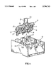
- FIG. 1 is a perspective view of a circuit breaker according to an embodiment of this invention, in which a switch mechanism unit and a case are separated from each other;
- FIG. 2 is a vertical cross sectional view of the circuit breaker shown in FIG. 1;
- FIG. 3(A) is a side view of a movable contact as shown in FIG. 1;
- FIG. 3(B) is a perspective view of the movable contact
- FIG. 4 is a perspective view, in which the movable contact shown in FIGS. 3(A), 3(B) is joined with a latch shown in FIG. 1;
- FIG. 5 is a perspective view of the latch and the movable contact shown in FIG. 4 as shown from the opposite direction;
- FIG. 6 is a side view for showing how to lock a tongue piece of the movable contact in a groove in the latch shown in FIG. 5;
- FIG. 7 is a side view for showing the tongue piece of the movable contact locked in the groove in the latch shown in FIG. 5;
- FIG. 8 is a perspective view for showing the movable contact and handle lever of the switch mechanism unit shown in FIG. 1 before joining;
- FIG. 9 is a cross sectional view of the integral part shown in FIG. 8.
- FIG. 10 is a vertical cross sectional view of a conventional circuit breaker, in which a switch mechanism and a case are separated from each other.
- FIG. 2 is a vertical cross sectional view showing the overall configuration of the circuit breaker, wherein the circuit breaker comprises a switch mechanism section and an overcurrent trap device which are accommodated in a container made of an insulating material comprising a case 12 and a cover 15.
- a current path is formed of an inverse-L-shaped fixed contact 16 having a power supply terminal 16a at one end and a fixed contact point 17 at the other end; a movable contact 4 having a movable contact point 18 that contacts the fixed contact point 17; a lead 19, one end of which is connected to the movable contact 4; a coil 22 in an overcurrent trap device 21 wherein the other end of the lead 19 is connected to one of the trap wires of the coil 22 via a relay terminal 20; and an L-shaped load terminal 23 to which the other trap wire of the coil 22 is connected.
- the movable contact 4 is rotatably joined with the tips of lever arms 25 of a handle lever 24 via protruding shafts 4a at the tops thereof.
- the handle lever 24 is rotatably supported by semi-circular bearing notches in the case 12 via a rotating shaft 26, and held by the cover 15 having semi-circular bearing notches corresponding to the above bearing notches.
- a switch spring 11 comprising a tension spring extends between the movable contact 4 and a latch 3, and the movable contact 4 is subjected to receive a rotational force caused by the tension of the switch spring 11 to act clockwise in the figure wherein the protruding shaft 4a serves as a supporting point, so that the movable contact point 18 is pressed against the fixed contact point 17.
- the latch 3 is rotatably supported by semi-circular bearing notches in the case 12 via a rotating shaft 27, and held by the cover 15 having the semi-circular bearing notches corresponding to these bearing notches.
- the latch 3 is subjected to receive a rotational force caused by the tension of the switch spring 11 to act clockwise in the figure wherein the rotating shaft 27 serves as a supporting point, but is retained in the illustrated position because the tip of an engaging arm 28 is engaged with a latch receiver 29.
- the latch receiver 29 is rotatably supported by a pin 30, and subjected to receive a rotational force provided by the latch 3 to act counterclockwise in the figure wherein the pin 30 serves as a supporting point.
- the latch receiver is retained in the illustrated position because a hook 29a abuts against a claw 31a of a stop bar 31.
- an armature 33 of an overcurrent trap device 21 is attracted to an armature 34 to press a trip arm 31b of a trip bar 31 to thereby rotate the trip bar 31 clockwise in the figure.
- the claw 31a of the trip bar 31 is removed from the hook 29a of a latch receiver 29, and the latch receiver 29 is rotated counterclockwise.
- the disengaged latch 3 is rotated clockwise in the figure, and the effect of the switch spring 11 on the movable contact 4 is reversed to thereby cause the movable contact 4 to be opened and disconnected from the fixed contact 16 (trip operation).
- FIG. 3(A) shows a side view of the movable contact 4
- FIG. 3(B) is a perspective view thereof.
- the movable contact 4 is formed to have a lateral pair of arms by a press-stamped plate conductor as illustrated.
- the movable contact point 18 is integrally joined with the movable contact 4 by press-fitting, and the protruding shafts 4a are integrally formed at the tips of the arms so as to protrude outwardly.
- a tongue piece 4b that is caught in the groove in the latch 3 is formed between the arms so as to extend vertically, and a spring peg 4c is formed by bending so as to extend laterally from one of the arms.
- the lead 19 (FIG. 2) is connected to the rear surface, i.e. the right end surface in FIG. 3(A), of the movable contact point 18 by spot welding.
- FIG. 4 is a perspective view showing the latch 3.
- the latch 3 is made of a molded resin, and includes the engaging arm 28 integrally formed in a central pole section so as to cross the rotating shaft 27.
- a spring peg 3a comprising a constricted shaft portion is integrally formed in the middle of each pole as illustrated.
- One end of the switch spring 11 with its other end caught around the spring peg 4c of the movable contact 4 is caught around the spring peg 3a to connect the latch 3 and the movable contact 4 together as illustrated.
- FIG. 5 shows the latch 3 in FIG. 4 as seen from the opposite direction.
- the latch 3 has a groove 3b of an L-shaped cross section in which the tongue piece 4b of the movable contact 4 is caught. Then, the movable contact 4 connected to the latch 3 is rotated in the direction shown by the arrow to lock the tip of the tongue piece 4b in the groove 3b, as shown in the side view in FIG. 6.
- FIG. 7 shows the state after this operation. In this case, the switch spring 11 is stretched, and this tension causes the movable contact 4 to be temporarily fixed to the latch 3 in the state shown in FIG. 7.
- FIG. 8 is a perspective view showing the latch 3 and the handle lever 24 with the movable contact 4 temporarily fixed thereto.
- the handle lever 24 is made of a molded resin, and comprises an operation handle 32 and three pairs of lever arms 25, i.e. each pair for each pole, that cross the rotating shaft 26 and are integrally formed so as to protrude in approximately opposite directions.
- U-shaped bearing notches 25a that receive the protruding shafts 4a of the movable contact 4 are formed in the inner opposite surfaces at the tips of the lever arms 25.
- FIG. 9 is an enlarged cross sectional view showing the bearing notch section. A circular recess in which the protruding shaft 4a is rotatably fitted is formed in a deep portion of the bearing notch 25a.
- FIG. 1 is a perspective view showing the switch mechanism unit 35 and the case 12.
- the case 12 includes a lateral pair of plate-like bearing sections 12a integrally extending vertically from the bottom, and semi-circular bearing notches 36 and 37 are formed in two longitudinal positions in the top surfaces of the bearing sections 12a.
- the switch mechanism unit 35 is inserted into the case 12 along the arrow shown in FIG. 1.
- the portions of the rotating shaft 27 of the latch 3 which are shown with diagonal lines in FIG. 5 are supported by the bearing notches 36, while the portions of the handle lever 24, one of which is shown with diagonal lines in FIG. 8, are supported by the bearing notches 37.
- bearing notches are formed in the cover 15, corresponding to the bearing notches 36, 37 as described above.
- the cover 15 is fixed on the case 12 by screws so that the bearing notches of the cover 15 abut against the bearing notches 36, 37.
- the movable contact 4 is pressed against the fixed contact 16 to cause the tongue piece 4b to be removed from the groove 3b of the latch 3, and the tension of the switch spring 11 then causes the movable contact point 18 to be pressed against the fixed contact 17.
- the switch spring 11 also has a function of a contact spring for generating a contact pressure between the movable and the fixed contact.
- the arms of the movable contact are joined with the lever arms of the handle lever; the switch spring extends between the latch and the movable contact to form a switch mechanism unit; and the handle lever and the latch are directly supported by the case.
- the switch mechanism unit can be assembled outside the case before it is incorporated into the case, to thereby eliminate the need for cumbersome operations to stretch the switch spring within a narrow case and to allow very easy assembly operations.
Abstract
Description
Claims (6)
Applications Claiming Priority (2)
| Application Number | Priority Date | Filing Date | Title |
|---|---|---|---|
| JP8-198364 | 1996-07-09 | ||
| JP19836496A JP3250650B2 (en) | 1996-07-09 | 1996-07-09 | Circuit breaker |
Publications (1)
| Publication Number | Publication Date |
|---|---|
| US5794763A true US5794763A (en) | 1998-08-18 |
Family
ID=16389885
Family Applications (1)
| Application Number | Title | Priority Date | Filing Date |
|---|---|---|---|
| US08/888,401 Expired - Lifetime US5794763A (en) | 1996-07-09 | 1997-07-07 | Circuit breaker |
Country Status (6)
| Country | Link |
|---|---|
| US (1) | US5794763A (en) |
| JP (1) | JP3250650B2 (en) |
| KR (1) | KR100429665B1 (en) |
| CN (1) | CN1076859C (en) |
| DE (1) | DE19729174B4 (en) |
| TW (1) | TW347543B (en) |
Cited By (5)
| Publication number | Priority date | Publication date | Assignee | Title |
|---|---|---|---|---|
| EP2061050A1 (en) | 2007-11-16 | 2009-05-20 | Schneider Electric Industries SAS | Electrical switchgear with rotating mobile contact(s) |
| US20110073451A1 (en) * | 2009-09-28 | 2011-03-31 | Gottschalk Andrew L | Electrical switching apparatus and shaft assembly therefor |
| US20110272259A1 (en) * | 2009-01-08 | 2011-11-10 | Abb S.P.A. | circuit-breaking device for low-voltage systems |
| US20130056339A1 (en) * | 2011-09-01 | 2013-03-07 | Socomec S.A. | Electrical cut-off device with high making capacity |
| US20130056337A1 (en) * | 2011-09-01 | 2013-03-07 | Socomec S.A. | Moving contact-carrying carriage and electrical cut-off device equipped with such carriage |
Families Citing this family (7)
| Publication number | Priority date | Publication date | Assignee | Title |
|---|---|---|---|---|
| JP3227670B2 (en) * | 1998-02-09 | 2001-11-12 | 富士電機株式会社 | Circuit breaker |
| JP4009892B2 (en) * | 2000-02-07 | 2007-11-21 | 富士電機機器制御株式会社 | Circuit breaker contactor device |
| DE10261853B3 (en) * | 2002-12-20 | 2004-04-22 | Siemens Ag | Multi-pole power switch for 3-phase load, has feedback torque exerted on switch shaft by one switch pole reduced relative to feedback torque exerted on switch shaft by further switch pole |
| US7569784B2 (en) * | 2006-10-13 | 2009-08-04 | Eaton Corporation | Electrical switching apparatus, and housing and integral pole shaft bearing assembly therefor |
| JP4814848B2 (en) * | 2007-08-09 | 2011-11-16 | 三菱電機株式会社 | Circuit breaker |
| KR200472736Y1 (en) * | 2012-12-05 | 2014-05-19 | 엘에스산전 주식회사 | Pivotable part structure of on/off device for circuit breaker |
| CN107026030B (en) * | 2016-02-02 | 2019-04-16 | 三信国际电器上海有限公司 | A kind of contact system of residual current action breaker |
Citations (3)
| Publication number | Priority date | Publication date | Assignee | Title |
|---|---|---|---|---|
| US4786771A (en) * | 1986-09-09 | 1988-11-22 | Mitsubishi Denki Kabushiki Kaisha | Circuit interrupter with two stage stopper preventing bounce back |
| US5302787A (en) * | 1992-05-05 | 1994-04-12 | Square D Company | Automatic miniature circuit breaker with Z-axis assemblable contact assembly |
| US5449871A (en) * | 1993-04-20 | 1995-09-12 | Merlin Gerin | Operating mechanism of a multipole electrical circuit breaker |
Family Cites Families (1)
| Publication number | Priority date | Publication date | Assignee | Title |
|---|---|---|---|---|
| JPS62130832A (en) | 1985-12-02 | 1987-06-13 | Yokohama Rubber Co Ltd:The | Automatic bead-inserting unit |
-
1996
- 1996-07-09 JP JP19836496A patent/JP3250650B2/en not_active Expired - Lifetime
-
1997
- 1997-07-04 KR KR1019970030951A patent/KR100429665B1/en not_active IP Right Cessation
- 1997-07-07 US US08/888,401 patent/US5794763A/en not_active Expired - Lifetime
- 1997-07-08 DE DE19729174A patent/DE19729174B4/en not_active Expired - Fee Related
- 1997-07-08 TW TW086109601A patent/TW347543B/en not_active IP Right Cessation
- 1997-07-09 CN CN97114534A patent/CN1076859C/en not_active Expired - Fee Related
Patent Citations (3)
| Publication number | Priority date | Publication date | Assignee | Title |
|---|---|---|---|---|
| US4786771A (en) * | 1986-09-09 | 1988-11-22 | Mitsubishi Denki Kabushiki Kaisha | Circuit interrupter with two stage stopper preventing bounce back |
| US5302787A (en) * | 1992-05-05 | 1994-04-12 | Square D Company | Automatic miniature circuit breaker with Z-axis assemblable contact assembly |
| US5449871A (en) * | 1993-04-20 | 1995-09-12 | Merlin Gerin | Operating mechanism of a multipole electrical circuit breaker |
Cited By (10)
| Publication number | Priority date | Publication date | Assignee | Title |
|---|---|---|---|---|
| EP2061050A1 (en) | 2007-11-16 | 2009-05-20 | Schneider Electric Industries SAS | Electrical switchgear with rotating mobile contact(s) |
| US20110272259A1 (en) * | 2009-01-08 | 2011-11-10 | Abb S.P.A. | circuit-breaking device for low-voltage systems |
| US8624138B2 (en) * | 2009-01-08 | 2014-01-07 | Abb S.P.A. | Circuit-breaking device for low-voltage systems |
| US20110073451A1 (en) * | 2009-09-28 | 2011-03-31 | Gottschalk Andrew L | Electrical switching apparatus and shaft assembly therefor |
| US8183483B2 (en) * | 2009-09-28 | 2012-05-22 | Eaton Corporation | Electrical switching apparatus and shaft assembly therefor |
| AU2010224436B2 (en) * | 2009-09-28 | 2013-06-20 | Eaton Intelligent Power Limited | Electrical switching apparatus and shaft assembly therefor |
| US20130056339A1 (en) * | 2011-09-01 | 2013-03-07 | Socomec S.A. | Electrical cut-off device with high making capacity |
| US20130056337A1 (en) * | 2011-09-01 | 2013-03-07 | Socomec S.A. | Moving contact-carrying carriage and electrical cut-off device equipped with such carriage |
| US8859916B2 (en) * | 2011-09-01 | 2014-10-14 | Socomec S.A. | Electrical cut-off device with high making capacity |
| US8993908B2 (en) * | 2011-09-01 | 2015-03-31 | Socomec S.A. | Moving contact-carrying carriage and electrical cut-off device equipped with such carriage |
Also Published As
| Publication number | Publication date |
|---|---|
| JP3250650B2 (en) | 2002-01-28 |
| JPH1027534A (en) | 1998-01-27 |
| CN1173033A (en) | 1998-02-11 |
| TW347543B (en) | 1998-12-11 |
| DE19729174A1 (en) | 1998-01-15 |
| KR980011563A (en) | 1998-04-30 |
| DE19729174B4 (en) | 2006-04-27 |
| KR100429665B1 (en) | 2004-07-19 |
| CN1076859C (en) | 2001-12-26 |
Similar Documents
| Publication | Publication Date | Title |
|---|---|---|
| US5794763A (en) | Circuit breaker | |
| KR970007515B1 (en) | Circuit breaker | |
| KR100908373B1 (en) | Drive motor used for closing spring charging device of air circuit breaker | |
| US4484164A (en) | Braidless movable contact with wiping action | |
| JP2002352689A (en) | Circuit breaker for wiring | |
| US4080582A (en) | Circuit breaker with improved trip mechanism | |
| US5874877A (en) | Circuit breaker | |
| CN102047371B (en) | Movable contactor device of circuit breaker | |
| US6333845B1 (en) | Power-supply breaker apparatus | |
| JP3374699B2 (en) | Circuit breaker | |
| US4339642A (en) | Current switching member for circuit breakers | |
| US4931602A (en) | Multipole circuit breaker | |
| KR100443137B1 (en) | Circuit breaker | |
| US5990434A (en) | Switching mechanism for circuit breaker | |
| JP3246564B2 (en) | Circuit breaker and method of assembling the same | |
| CN217881379U (en) | Plastic case circuit breaker | |
| US4554423A (en) | Molded case circuit breaker with adjacent pole mechanisms spaced closer than adjacent terminals | |
| JP2953073B2 (en) | Mounting device for switching mechanism support frame in circuit breaker | |
| JP3503534B2 (en) | Electromagnetic trip device for circuit breakers | |
| JP3097355B2 (en) | Circuit breaker | |
| JPH0715088Y2 (en) | Circuit breaker | |
| KR880000701B1 (en) | Multipolar circuit breaker | |
| JP3232836B2 (en) | Neutral device for circuit breakers | |
| JP2000040458A (en) | Circuit breaker | |
| JP2724027B2 (en) | Circuit breaker |
Legal Events
| Date | Code | Title | Description |
|---|---|---|---|
| AS | Assignment |
Owner name: FUJI ELECTRIC CO., LTD., JAPAN Free format text: ASSIGNMENT OF ASSIGNORS INTEREST;ASSIGNOR:OGASAWARA, MAKOTO;REEL/FRAME:008674/0720 Effective date: 19970702 |
|
| STCF | Information on status: patent grant |
Free format text: PATENTED CASE |
|
| FEPP | Fee payment procedure |
Free format text: PAYOR NUMBER ASSIGNED (ORIGINAL EVENT CODE: ASPN); ENTITY STATUS OF PATENT OWNER: LARGE ENTITY |
|
| FPAY | Fee payment |
Year of fee payment: 4 |
|
| FPAY | Fee payment |
Year of fee payment: 8 |
|
| AS | Assignment |
Owner name: FUJI ELECTRIC FA COMPONENTS & SYSTEMS CO., LTD., J Free format text: ASSIGNMENT OF ASSIGNORS INTEREST;ASSIGNOR:FUJI ELECTRIC HOLDINGS CO., LTD.;REEL/FRAME:021531/0990 Effective date: 20080825 |
|
| AS | Assignment |
Owner name: FUJI ELECTRIC FA COMPONENTS & SYSTEMS CO., LTD., J Free format text: ASSIGNMENT OF ASSIGNORS INTEREST;ASSIGNOR:FUJI ELECTRIC FA COMPONENTS & SYSTEMS CO., LTD.;REEL/FRAME:022380/0001 Effective date: 20081001 Owner name: FUJI ELECTRIC FA COMPONENTS & SYSTEMS CO., LTD.,JA Free format text: ASSIGNMENT OF ASSIGNORS INTEREST;ASSIGNOR:FUJI ELECTRIC FA COMPONENTS & SYSTEMS CO., LTD.;REEL/FRAME:022380/0001 Effective date: 20081001 |
|
| FPAY | Fee payment |
Year of fee payment: 12 |