US5791041A - Device for producing battery electrodes and method for producing the same - Google Patents
Device for producing battery electrodes and method for producing the same Download PDFInfo
- Publication number
- US5791041A US5791041A US08/649,766 US64976696A US5791041A US 5791041 A US5791041 A US 5791041A US 64976696 A US64976696 A US 64976696A US 5791041 A US5791041 A US 5791041A
- Authority
- US
- United States
- Prior art keywords
- bobbin
- strip
- electrode
- spiral
- cross
- Prior art date
- Legal status (The legal status is an assumption and is not a legal conclusion. Google has not performed a legal analysis and makes no representation as to the accuracy of the status listed.)
- Expired - Lifetime
Links
Images


Classifications
-
- H—ELECTRICITY
- H01—ELECTRIC ELEMENTS
- H01M—PROCESSES OR MEANS, e.g. BATTERIES, FOR THE DIRECT CONVERSION OF CHEMICAL ENERGY INTO ELECTRICAL ENERGY
- H01M6/00—Primary cells; Manufacture thereof
- H01M6/04—Cells with aqueous electrolyte
- H01M6/06—Dry cells, i.e. cells wherein the electrolyte is rendered non-fluid
- H01M6/10—Dry cells, i.e. cells wherein the electrolyte is rendered non-fluid with wound or folded electrodes
-
- H—ELECTRICITY
- H01—ELECTRIC ELEMENTS
- H01M—PROCESSES OR MEANS, e.g. BATTERIES, FOR THE DIRECT CONVERSION OF CHEMICAL ENERGY INTO ELECTRICAL ENERGY
- H01M50/00—Constructional details or processes of manufacture of the non-active parts of electrochemical cells other than fuel cells, e.g. hybrid cells
- H01M50/50—Current conducting connections for cells or batteries
- H01M50/531—Electrode connections inside a battery casing
- H01M50/534—Electrode connections inside a battery casing characterised by the material of the leads or tabs
-
- Y—GENERAL TAGGING OF NEW TECHNOLOGICAL DEVELOPMENTS; GENERAL TAGGING OF CROSS-SECTIONAL TECHNOLOGIES SPANNING OVER SEVERAL SECTIONS OF THE IPC; TECHNICAL SUBJECTS COVERED BY FORMER USPC CROSS-REFERENCE ART COLLECTIONS [XRACs] AND DIGESTS
- Y02—TECHNOLOGIES OR APPLICATIONS FOR MITIGATION OR ADAPTATION AGAINST CLIMATE CHANGE
- Y02P—CLIMATE CHANGE MITIGATION TECHNOLOGIES IN THE PRODUCTION OR PROCESSING OF GOODS
- Y02P70/00—Climate change mitigation technologies in the production process for final industrial or consumer products
- Y02P70/50—Manufacturing or production processes characterised by the final manufactured product
-
- Y—GENERAL TAGGING OF NEW TECHNOLOGICAL DEVELOPMENTS; GENERAL TAGGING OF CROSS-SECTIONAL TECHNOLOGIES SPANNING OVER SEVERAL SECTIONS OF THE IPC; TECHNICAL SUBJECTS COVERED BY FORMER USPC CROSS-REFERENCE ART COLLECTIONS [XRACs] AND DIGESTS
- Y10—TECHNICAL SUBJECTS COVERED BY FORMER USPC
- Y10T—TECHNICAL SUBJECTS COVERED BY FORMER US CLASSIFICATION
- Y10T29/00—Metal working
- Y10T29/49—Method of mechanical manufacture
- Y10T29/49002—Electrical device making
- Y10T29/49108—Electric battery cell making
-
- Y—GENERAL TAGGING OF NEW TECHNOLOGICAL DEVELOPMENTS; GENERAL TAGGING OF CROSS-SECTIONAL TECHNOLOGIES SPANNING OVER SEVERAL SECTIONS OF THE IPC; TECHNICAL SUBJECTS COVERED BY FORMER USPC CROSS-REFERENCE ART COLLECTIONS [XRACs] AND DIGESTS
- Y10—TECHNICAL SUBJECTS COVERED BY FORMER USPC
- Y10T—TECHNICAL SUBJECTS COVERED BY FORMER US CLASSIFICATION
- Y10T29/00—Metal working
- Y10T29/49—Method of mechanical manufacture
- Y10T29/49002—Electrical device making
- Y10T29/49117—Conductor or circuit manufacturing
- Y10T29/49124—On flat or curved insulated base, e.g., printed circuit, etc.
-
- Y—GENERAL TAGGING OF NEW TECHNOLOGICAL DEVELOPMENTS; GENERAL TAGGING OF CROSS-SECTIONAL TECHNOLOGIES SPANNING OVER SEVERAL SECTIONS OF THE IPC; TECHNICAL SUBJECTS COVERED BY FORMER USPC CROSS-REFERENCE ART COLLECTIONS [XRACs] AND DIGESTS
- Y10—TECHNICAL SUBJECTS COVERED BY FORMER USPC
- Y10T—TECHNICAL SUBJECTS COVERED BY FORMER US CLASSIFICATION
- Y10T29/00—Metal working
- Y10T29/53—Means to assemble or disassemble
- Y10T29/5313—Means to assemble electrical device
- Y10T29/532—Conductor
- Y10T29/53204—Electrode
Definitions
- the present invention relates to a device for producing a battery electrodes comprising a positive electrode strip, a negative electrode strip and a separator strip, all of which are spirally wound.
- the present invention also relates to a method for producing the same.
- the bobbin 1 is further turned so that a superimposing strip consisting of the separator 2, a positive electrode strip 3 and a negative electrode strip 4 is spirally wound around the circumference of the bobbin 1 to form a spirally wound body (coil).
- the coil is inserted into a cylindrical metal case 6, and then the bobbin 1 is extracted from the coil to produce a spiral electrodes.
- EP 655793 discloses a method for producing an electrode assembly in which an anode and a cathode are wound together in a unidirectional winding having substantially straight sides by using a correspondingly shaped mandrel.
- Another object of the invention is to provide a method for producing a battery electrode including a step of extracting a bobbin while forming a center hole of the battery electrode having a desired shape.
- FIG. 1 is a schematic illustration of a spiral electrode manufactured by means of a bobbin according to a first embodiment of the present invention
- FIG. 2 is a schematic illustration of a method for manufacturing a spiral electrodes by means of the bobbin according to the first embodiment of the present invention
- FIG. 3 is a side view of the bobbin according to the first embodiment of the present invention.
- FIG. 4 is a cross-sectional view of a electrode manufactured by means of the bobbin according to the first embodiment of the present invention
- FIG. 5 is a schematic illustration of a bobbin according to a second embodiment of the present invention.
- FIG. 6 is a schematic illustration of a manufacturing step of welding a lead portion on the negative side of the spiral electrode to a cylindrical metal case according to the present invention
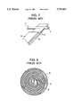
- FIG. 7 is a schematic illustration of a conventional method for manufacturing a spiral electrode by means of a conventional bobbin.
- FIG. 8 is a cross-sectional view of the spiral electrode according to the conventional method.
- a bobbin 1 comprises one piece 1A of the bobbin 1 and the other piece 1B of the bobbin 1, the one piece 1A having one portion of semi-circular cross section, around which portion an electrode is spirally wound, and the other portion of a circular cross section with a diameter of 3 mm at a tip thereof, and the other piece 1B having a semi-circular cross section that forms a circular cross section with a diameter of 3 mm when the other piece 1B is placed over the one piece 1A at a bobbin slope 10 of the one piece 1A.
- a separator strip 2, a positive electrode strip 3, and a negative electrode strip 4 are piled up together and then spirally wound around the outer circumference of the bobbin 1 to form a spiral electrode 5.
- the other piece 1B is first extracted from the spiral electrode 5 in the direction indicated by an arrow B, and secondly the spiral electrode 5 is removed from the one piece 1A toward the direction indicated by an arrow A.
- the center hole 9 of the spiral electrode 5 is formed to be substantially circular in shape since the end of the one piece 1A has a circular cross section as shown in FIG. 1.
- the spiral electrode 5 is inserted into a cylindrical metal case 6 with a lead portion 7 on the negative side of the spiral electrode 5 downwardly, of which the lead portion 7 is welded to the bottom inside 11 of the cylindrical metal case 6.
- a "bent portion" of the separator strip 2, which is left in the center hole 9 of the spiral electrode 5, and the deformation of the center hole 9 itself may cause the separator 2 or the spiral electrode 5 to interfere with a welding apparatus 8, so that an inferior battery electrode is produced. According to the embodiment of the present invention, such defects can be prevented.
- the tapered part of the bobbin 1 prevents the separator 2 from being unnecessarily put between the bobbin pieces 1A, 1B and facilitates extraction of the bobbin when forming the spiral electrode 5.
- FIG. 5 shows a second embodiment of the present invention.
- a bobbin 1 having a guide groove, in which an inclined surface for receiving the separator strip 2 is formed.
- An insulator strip such as the separator strip 2 is put between the guide groove of the bobbin 1 and attached to the guide groove.
- the bobbin 1 is turned so that the insulator strip is spirally wound around the outer circumference thereof to form a spiral electrode.
- the bobbin is then extracted from the spiral electrode, so that the center hole of the bobbin is formed to be substantially circular in shape without the "bent portion" of the separator strip 2.
- the center hole has substantially a circular shape, however, it may have any other shape such as a rectangular shape or an elliptical shape.
- the bobbin consists of two pieces or a single piece, however, it may consist of more than three pieces.
- the cross section of the end of the bobbin is not equivalent in shape with that of the center hole, it is possible to form the center hole into a circular shape by extracting the bobbin from the electrode while turning the bobbin.
- spiral electrodes were produced by the method of the first embodiment, and the same number of the spiral electrodes were produced by a conventional method.
- the spiral electrodes produced by both methods were respectively inserted into a cylindrical iron case, and their lead portion of nickel on the negative side of the spiral electrodes were welded to the inside of the cylinder iron cases.
- the proportion of rejects due to the interference of the welding apparatus with the separator strip 2 during welding was respectively measured.
Landscapes
- Engineering & Computer Science (AREA)
- Manufacturing & Machinery (AREA)
- Chemical & Material Sciences (AREA)
- Chemical Kinetics & Catalysis (AREA)
- Electrochemistry (AREA)
- General Chemical & Material Sciences (AREA)
- Secondary Cells (AREA)
- Primary Cells (AREA)
Abstract
Description
______________________________________
             Proportion of rejects when
             welding the negative terminal
             side lead and the inside of
             the cylindrical iron case
______________________________________
Manufacturing method
                3%
according to first
embodiment
Conventional   12%
manufacturing method
______________________________________
Claims (5)
Applications Claiming Priority (2)
| Application Number | Priority Date | Filing Date | Title |
|---|---|---|---|
| JP12224595A JP3379282B2 (en) | 1995-05-22 | 1995-05-22 | Apparatus and method for producing battery electrode body |
| JP7-122245 | 1995-05-22 |
Publications (1)
| Publication Number | Publication Date |
|---|---|
| US5791041A true US5791041A (en) | 1998-08-11 |
Family
ID=14831190
Family Applications (1)
| Application Number | Title | Priority Date | Filing Date |
|---|---|---|---|
| US08/649,766 Expired - Lifetime US5791041A (en) | 1995-05-22 | 1996-05-15 | Device for producing battery electrodes and method for producing the same |
Country Status (4)
| Country | Link |
|---|---|
| US (1) | US5791041A (en) |
| EP (1) | EP0744783B1 (en) |
| JP (1) | JP3379282B2 (en) |
| DE (1) | DE69601049T2 (en) |
Cited By (9)
| Publication number | Priority date | Publication date | Assignee | Title |
|---|---|---|---|---|
| US20020072668A1 (en) * | 2000-12-13 | 2002-06-13 | Image-Guided Neurologics, Inc. | Microcoil construction |
| US6534952B1 (en) * | 1999-11-08 | 2003-03-18 | Matsushita Electric Industrial Co., Ltd. | Spiral electrode group winding method and device and battery using them |
| US20130316207A1 (en) * | 2011-02-03 | 2013-11-28 | Sanyo Electric Co., Ltd. | Nonaqueous electrolyte secondary battery |
| US8685557B2 (en) | 2010-04-07 | 2014-04-01 | Medtronic, Inc. | Electrode assembly including mandrel having a removable portion |
| US8832914B2 (en) | 2010-10-06 | 2014-09-16 | Medtronic, Inc | Coiling device for making an electrode assembly and methods of use |
| US9005802B2 (en) | 2011-12-21 | 2015-04-14 | Medtronic, Inc. | Electrode assembly with hybrid weld |
| US9054387B2 (en) | 2010-04-07 | 2015-06-09 | Medtronic, Inc. | Electrode assembly including mandrel having removable portion |
| US9083053B2 (en) | 2011-12-21 | 2015-07-14 | Medtronic, Inc. | Through weld interconnect joint |
| US9299971B2 (en) | 2010-10-06 | 2016-03-29 | Medtronic, Inc. | Common carrier for the integrated mandrel battery assembly |
Families Citing this family (4)
| Publication number | Priority date | Publication date | Assignee | Title |
|---|---|---|---|---|
| JP4363677B2 (en) * | 1998-01-30 | 2009-11-11 | Oppc株式会社 | Battery electrode body manufacturing method and manufacturing apparatus |
| KR101678979B1 (en) * | 2015-01-02 | 2016-11-23 | 주식회사 엘지화학 | Double bent type Reform pin |
| JP6567310B2 (en) * | 2015-03-30 | 2019-08-28 | 株式会社皆藤製作所 | Winding core, winding core rotating device and winding method |
| JP6590358B1 (en) * | 2019-07-25 | 2019-10-16 | 株式会社皆藤製作所 | Winding core, winding core rotating device and winding method |
Citations (10)
| Publication number | Priority date | Publication date | Assignee | Title |
|---|---|---|---|---|
| US3373060A (en) * | 1965-12-01 | 1968-03-12 | Texas Instruments Inc | Electrical cell with coiled separators and electrodes |
| US3734778A (en) * | 1971-05-10 | 1973-05-22 | Gates Rubber Co | Method for producing a spirally wound electrolytic cell |
| US4559700A (en) * | 1984-09-10 | 1985-12-24 | General Electric Company | Method for winding an electrode assembly |
| US4709472A (en) * | 1985-12-23 | 1987-12-01 | Sanyo Electric Co., Ltd. | Method of manufacturing spiral electrode assembly |
| EP0283813A1 (en) * | 1987-03-12 | 1988-09-28 | SAFT (inscrite au Registre du Commerce sous le numéro 343 588 737) | Method for making an electrochemical generator with alcaline electrolyte and spirally wound electrodes |
| US5017442A (en) * | 1988-03-19 | 1991-05-21 | Hitachi Maxell, Ltd. | Coiled lithium battery |
| EP0655793A2 (en) * | 1993-11-19 | 1995-05-31 | Medtronic, Inc. | High-reliability electrochemical cell and electrode assembly therefor |
| US5434017A (en) * | 1993-11-19 | 1995-07-18 | Medtronic, Inc. | Isolated connection for an electrochemical cell |
| US5439760A (en) * | 1993-11-19 | 1995-08-08 | Medtronic, Inc. | High reliability electrochemical cell and electrode assembly therefor |
| US5486215A (en) * | 1993-11-19 | 1996-01-23 | Medtronic, Inc. | Electrode assembly and method |
Family Cites Families (1)
| Publication number | Priority date | Publication date | Assignee | Title |
|---|---|---|---|---|
| JPS5866270A (en) * | 1981-10-15 | 1983-04-20 | Matsushita Electric Ind Co Ltd | Manufacturing method for spiral electrode body |
-
1995
- 1995-05-22 JP JP12224595A patent/JP3379282B2/en not_active Expired - Lifetime
-
1996
- 1996-05-15 US US08/649,766 patent/US5791041A/en not_active Expired - Lifetime
- 1996-05-20 DE DE69601049T patent/DE69601049T2/en not_active Expired - Lifetime
- 1996-05-20 EP EP96108023A patent/EP0744783B1/en not_active Expired - Lifetime
Patent Citations (11)
| Publication number | Priority date | Publication date | Assignee | Title |
|---|---|---|---|---|
| US3373060A (en) * | 1965-12-01 | 1968-03-12 | Texas Instruments Inc | Electrical cell with coiled separators and electrodes |
| US3734778A (en) * | 1971-05-10 | 1973-05-22 | Gates Rubber Co | Method for producing a spirally wound electrolytic cell |
| US4559700A (en) * | 1984-09-10 | 1985-12-24 | General Electric Company | Method for winding an electrode assembly |
| US4709472A (en) * | 1985-12-23 | 1987-12-01 | Sanyo Electric Co., Ltd. | Method of manufacturing spiral electrode assembly |
| EP0283813A1 (en) * | 1987-03-12 | 1988-09-28 | SAFT (inscrite au Registre du Commerce sous le numéro 343 588 737) | Method for making an electrochemical generator with alcaline electrolyte and spirally wound electrodes |
| US4802275A (en) * | 1987-03-12 | 1989-02-07 | Saft, S.A. | Method of manufacturing an electrochemical cell having an alkaline electrolyte and spiral-wound electrodes |
| US5017442A (en) * | 1988-03-19 | 1991-05-21 | Hitachi Maxell, Ltd. | Coiled lithium battery |
| EP0655793A2 (en) * | 1993-11-19 | 1995-05-31 | Medtronic, Inc. | High-reliability electrochemical cell and electrode assembly therefor |
| US5434017A (en) * | 1993-11-19 | 1995-07-18 | Medtronic, Inc. | Isolated connection for an electrochemical cell |
| US5439760A (en) * | 1993-11-19 | 1995-08-08 | Medtronic, Inc. | High reliability electrochemical cell and electrode assembly therefor |
| US5486215A (en) * | 1993-11-19 | 1996-01-23 | Medtronic, Inc. | Electrode assembly and method |
Cited By (14)
| Publication number | Priority date | Publication date | Assignee | Title |
|---|---|---|---|---|
| US6534952B1 (en) * | 1999-11-08 | 2003-03-18 | Matsushita Electric Industrial Co., Ltd. | Spiral electrode group winding method and device and battery using them |
| US7210223B2 (en) * | 2000-12-13 | 2007-05-01 | Image-Guided Neurologics, Inc. | Method of manufacturing a microcoil construction |
| US20070287903A1 (en) * | 2000-12-13 | 2007-12-13 | Image-Guided Neurologics, Inc. | Microcoil construction |
| US7774043B2 (en) | 2000-12-13 | 2010-08-10 | Medtronic, Inc. | Microcoil construction |
| US8146239B2 (en) | 2000-12-13 | 2012-04-03 | Medtronic, Inc. | Method of forming microcoil with conducting trace and attaching trace |
| US20020072668A1 (en) * | 2000-12-13 | 2002-06-13 | Image-Guided Neurologics, Inc. | Microcoil construction |
| US9054387B2 (en) | 2010-04-07 | 2015-06-09 | Medtronic, Inc. | Electrode assembly including mandrel having removable portion |
| US8685557B2 (en) | 2010-04-07 | 2014-04-01 | Medtronic, Inc. | Electrode assembly including mandrel having a removable portion |
| US8832914B2 (en) | 2010-10-06 | 2014-09-16 | Medtronic, Inc | Coiling device for making an electrode assembly and methods of use |
| US9299971B2 (en) | 2010-10-06 | 2016-03-29 | Medtronic, Inc. | Common carrier for the integrated mandrel battery assembly |
| US20130316207A1 (en) * | 2011-02-03 | 2013-11-28 | Sanyo Electric Co., Ltd. | Nonaqueous electrolyte secondary battery |
| US9350042B2 (en) * | 2011-02-03 | 2016-05-24 | Sanyo Electric Co., Ltd. | Nonaqueous electrolyte secondary battery |
| US9083053B2 (en) | 2011-12-21 | 2015-07-14 | Medtronic, Inc. | Through weld interconnect joint |
| US9005802B2 (en) | 2011-12-21 | 2015-04-14 | Medtronic, Inc. | Electrode assembly with hybrid weld |
Also Published As
| Publication number | Publication date |
|---|---|
| JP3379282B2 (en) | 2003-02-24 |
| EP0744783A1 (en) | 1996-11-27 |
| DE69601049D1 (en) | 1999-01-14 |
| EP0744783B1 (en) | 1998-12-02 |
| JPH08315830A (en) | 1996-11-29 |
| DE69601049T2 (en) | 1999-06-10 |
Similar Documents
| Publication | Publication Date | Title |
|---|---|---|
| US5791041A (en) | Device for producing battery electrodes and method for producing the same | |
| US8734537B2 (en) | Battery production method | |
| US5021306A (en) | Spiral-wound galvanic cell | |
| DE10027001A1 (en) | Secondary battery for storage of electrical energy, has non-aqueous electrolyte and connecting component constructed to fix winding core on container with protruding surface to press internal lead onto core | |
| CN111370637B (en) | Production method of button cell without welding trace and prepared button cell | |
| JPH0312410B2 (en) | ||
| JPH09330697A (en) | Battery | |
| CA1326185C (en) | Copper core side electrode spark plug shell | |
| CN211957808U (en) | Button cell with no trace welded structure | |
| CN111370638A (en) | Production method of button battery without welding trace and button battery manufactured by same | |
| JPS6025164A (en) | Manufacture of spiral electrode having non-circular cross section | |
| JP2725523B2 (en) | Method of manufacturing battery with spiral electrode | |
| CN210778193U (en) | Inductance coil structure | |
| JPS5942783A (en) | Manufacture of spiral battery | |
| US11972910B2 (en) | Electrolytic capacitor and manufacturing method therefor | |
| JPH01238009A (en) | Manufacture of electrolytic capacitor element | |
| US20230137973A1 (en) | Electrolytic capacitor and manufacturing method therefor | |
| JP2002334691A (en) | Current collector of battery and manufacturing method of battery using the same | |
| CN116565294A (en) | Manufacturing method of multipolar lug cylindrical lithium ion battery cell and battery | |
| JP3217982B2 (en) | Battery and manufacturing method thereof | |
| JPS6177253A (en) | Manufacture of storage battery having spiral plate | |
| JPS6324610Y2 (en) | ||
| JPS62123652A (en) | Formation of cylindrical negative electrode in bobbin type lithium battery | |
| JP2021068655A (en) | Method for connecting lead tab with electrode foil, and method for manufacturing wound type power storage element | |
| JPH0917410A (en) | Manufacture of battery electrode |
Legal Events
| Date | Code | Title | Description |
|---|---|---|---|
| AS | Assignment |
Owner name: MATSUSHITA ELECTRIC INDUSTRIAL CO., LTD., JAPAN Free format text: ASSIGNMENT OF ASSIGNORS INTEREST;ASSIGNORS:MIYATA, KYOSUKE;KANEDA, YOSHIMITU;YONEDA, TAKASHI;REEL/FRAME:008008/0020 Effective date: 19960513 |
|
| STCF | Information on status: patent grant |
Free format text: PATENTED CASE |
|
| FEPP | Fee payment procedure |
Free format text: PAYOR NUMBER ASSIGNED (ORIGINAL EVENT CODE: ASPN); ENTITY STATUS OF PATENT OWNER: LARGE ENTITY |
|
| FPAY | Fee payment |
Year of fee payment: 4 |
|
| FPAY | Fee payment |
Year of fee payment: 8 |
|
| FPAY | Fee payment |
Year of fee payment: 12 |
|
| AS | Assignment |
Owner name: GODO KAISHA IP BRIDGE 1, JAPAN Free format text: ASSIGNMENT OF ASSIGNORS INTEREST;ASSIGNOR:PANASONIC CORPORATION (FORMERLY MATSUSHITA ELECTRIC INDUSTRIAL CO., LTD.);REEL/FRAME:032152/0514 Effective date: 20140117 |