US5787663A - Beam support bracket for a raised access floor - Google Patents
Beam support bracket for a raised access floor Download PDFInfo
- Publication number
- US5787663A US5787663A US08/796,542 US79654297A US5787663A US 5787663 A US5787663 A US 5787663A US 79654297 A US79654297 A US 79654297A US 5787663 A US5787663 A US 5787663A
- Authority
- US
- United States
- Prior art keywords
- support
- access floor
- raised access
- section
- stringer
- Prior art date
- Legal status (The legal status is an assumption and is not a legal conclusion. Google has not performed a legal analysis and makes no representation as to the accuracy of the status listed.)
- Expired - Fee Related
Links
Images


Classifications
-
- E—FIXED CONSTRUCTIONS
- E04—BUILDING
- E04B—GENERAL BUILDING CONSTRUCTIONS; WALLS, e.g. PARTITIONS; ROOFS; FLOORS; CEILINGS; INSULATION OR OTHER PROTECTION OF BUILDINGS
- E04B5/00—Floors; Floor construction with regard to insulation; Connections specially adapted therefor
- E04B5/02—Load-carrying floor structures formed substantially of prefabricated units
- E04B5/14—Load-carrying floor structures formed substantially of prefabricated units with beams or girders laid in two directions
-
- E—FIXED CONSTRUCTIONS
- E04—BUILDING
- E04F—FINISHING WORK ON BUILDINGS, e.g. STAIRS, FLOORS
- E04F15/00—Flooring
- E04F15/02—Flooring or floor layers composed of a number of similar elements
- E04F15/024—Sectional false floors, e.g. computer floors
- E04F15/02447—Supporting structures
- E04F15/02458—Framework supporting the panels
-
- Y—GENERAL TAGGING OF NEW TECHNOLOGICAL DEVELOPMENTS; GENERAL TAGGING OF CROSS-SECTIONAL TECHNOLOGIES SPANNING OVER SEVERAL SECTIONS OF THE IPC; TECHNICAL SUBJECTS COVERED BY FORMER USPC CROSS-REFERENCE ART COLLECTIONS [XRACs] AND DIGESTS
- Y10—TECHNICAL SUBJECTS COVERED BY FORMER USPC
- Y10T—TECHNICAL SUBJECTS COVERED BY FORMER US CLASSIFICATION
- Y10T403/00—Joints and connections
- Y10T403/44—Three or more members connected at single locus
-
- Y—GENERAL TAGGING OF NEW TECHNOLOGICAL DEVELOPMENTS; GENERAL TAGGING OF CROSS-SECTIONAL TECHNOLOGIES SPANNING OVER SEVERAL SECTIONS OF THE IPC; TECHNICAL SUBJECTS COVERED BY FORMER USPC CROSS-REFERENCE ART COLLECTIONS [XRACs] AND DIGESTS
- Y10—TECHNICAL SUBJECTS COVERED BY FORMER USPC
- Y10T—TECHNICAL SUBJECTS COVERED BY FORMER US CLASSIFICATION
- Y10T403/00—Joints and connections
- Y10T403/57—Distinct end coupler
- Y10T403/5733—Plural opposed sockets
Definitions
- the present invention relates generally to a raised access floor construction and raised access floor understructure modification method and, more specifically, to a beam support bracket which allows additional support beams to be installed in a raised access floor quadrant section.
- Raised access floor installations are commonly used in computer and telemarketing centers, electronics and biomedical manufacturing and research facilities, "clean" industrial rooms, or any other institution where specific climate control is required.
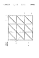
- a raised access floor is typically constructed using rectangular or square panels extending horizontally and supported, at least at their corners, by pedestals arranged on an understructure 10 which is a grid of quadrant sections 20 as seen in FIG. 1.
- each quadrant section 20, nine of which are shown in FIG. 1 includes four horizontal stringer support beams 21 arranged in a frame shape.
- Each stringer support beam 21 has three evenly spaced adjacent pedestal assemblies 22 associated with the beam. Two of these pedestal assemblies 22 are positioned at the extreme ends of the stringer support beam 21 and have respective vertical columns 24 coupled to them and extending to the floor.
- the third pedestal assembly 23 is positioned midway between the other two pedestal assemblies 22 at a central position of the stringer support beam 21.
- a common configuration has the pedestals arranged on four foot centers.
- Each quadrant section has a daisy wheel assembly 26 at each of the four corners of the frame, as seen in FIG. 2.
- the daisy wheel assembly 26 functions as a corner support for the stringer beams and is located between the corner pedestal assembly 22 and the vertical column 24 extending to the building floor.
- Each quadrant section 20 also includes a diagonal support beam 25 connected diagonally between the lower left hand corner of the quadrant section and the upper right hand corner as shown in FIG. 1.
- Each diagonal support beam 25 has three evenly spaced pedestals associated with it as shown in FIG. 1 and FIG. 2.
- the panels are arranged to form a work area floor and are spaced a predetermined distance above and parallel to the building floor by means of the support provided by this grid of pedestals and quadrant sections.
- Each 4' by 4' quadrant section supports four 2' by 2' panels.
- the panels which form the work area floor are each individually readily removable to allow easy access to the area between the building floor and the work area floor.
- Modifications may include removing the diagonal beam support from a quadrant section or cutting off part of the raised access floor construction in order to install a piece of equipment or other obstruction. When such modifications are made, additional structural support for the remaining panels surrounding the obstruction often becomes necessary.
- a first beam support bracket is provided that is capable of being mounted at any position along the length of a first stringer horizontal support beam of said raised access floor quadrant section.
- a mid-span horizontal support beam having first and second ends, is installed across a portion of the area within said frame and is attached to the first beam support bracket at its first end.
- a second beam support bracket is provided for being mounted at a corresponding position along the length of a second stringer horizontal support beam of said raised access floor quadrant section and is attached to said mid-span horizontal support beam at its second end.
- the first and second beam support brackets are preferably constructed of rectangular tubing, and this tubing is preferably made of carbon steel.
- the first and second beam support brackets are preferably painted with a two part conductive epoxy paint.
- the quadrant section is preferably of a four foot on center construction.
- the first and second beam support brackets preferably each comprise a cut-out section for interconnection with a pedestal assembly on a support beam of said raised access floor quadrant section. Also, the first and second beam support brackets may each comprise a saddle section for mounting the bracket over one of the stringer support beams.
- a first beam support bracket is provided that is capable of being mounted at any position along the length of a first stringer horizontal support beam of the raised access floor quadrant section.
- a first mid-span horizontal support beam having first and second ends, is installed across a portion of the area within the frame and attached to the first beam support bracket at its first end.
- a daisy wheel is provided that is mounted on a second stringer horizontal support beam of said raised access floor quadrant section and attached to the first mid-span horizontal support beam at its second end.
- a second beam support bracket having first and second beam support extensions, is mounted on said first mid-span horizontal support beam between said first and second ends of said first mid-span horizontal support beam.
- a second mid-span horizontal support beam having first and second ends, is installed across a portion of the area within the frame and attached at its first end to said first beam support extension of the second beam support bracket.
- a third beam support bracket is mounted at a corresponding position along the length of a third stringer horizontal support beam of the raised access floor quadrant section and attached to the second mid-span horizontal support beam at its second end.
- a third mid-span horizontal support beam having first and second ends, is installed across a portion of the area within the frame and attached at its first end to the second beam support extension of the second beam support bracket.
- a second daisy wheel is mounted on a fourth stringer horizontal support beam of the raised access floor quadrant section and attached to the third mid-span horizontal support beam at its second end.
- the objects and purpose of the invention are achieved by a method of modifying a raised access floor quadrant section construction having adjacent stringer support beams forming a frame.
- the method comprises the steps of mounting a first beam support bracket on a first stringer support beam of said frame, mounting a second beam support bracket on a second stringer support beam of said frame, and installing a third support beam, having first and second ends, at any desired location in the mid-span of said adjacent stringer support beams by connecting said first and second ends to said first and second beam support brackets, respectively.
- FIG. 1 is a plan view of a conventional understructure for a raised access floor
- FIG. 2 is a perspective view of a conventional raised access floor quadrant section
- FIG. 3 is a plan view of a modified understructure for a raised access floor according to a preferred embodiment of the present invention showing adjustable pedestals and beam support brackets installed;
- FIG. 4 is a perspective view of a modified understructure for a raised access floor according to a preferred embodiment of the present invention showing adjustable pedestals and beam support brackets installed;
- FIG. 5 is a perspective view of a beam support bracket according to a preferred embodiment of the present invention.
- FIG. 6A is a side view of the beam support bracket of FIG. 5;
- FIG. 6B is an end view of the beam support bracket of FIG. 5;
- FIG. 7 is a perspective view of the beam support bracket of FIG. 5 installed on a stringer support beam of the raised access floor quadrant section with two additional support beams connected to the bracket;
- FIG. 8A is a plan view of another embodiment of the beam support bracket of the instant invention.
- FIG. 8B is a side view of the beam support bracket embodiment of FIG. 8A.
- Modifications may include removing the diagonal beam support 25 or cutting off part of the raised access floor construction (i.e. part or all of a stringer support beam) in order to install a piece of equipment or other obstruction.
- a number of quadrant sections of the raised access floor understructure will have to be modified to make way for this obstruction. When such modifications are made, additional structural support for the panels often becomes necessary within the quadrant sections.
- FIG. 1 is a plan view of an understructure construction of a raised access floor without such an obstruction installed
- FIG. 3 is a plan view of the same understructure for a raised access floor with modifications made to each of the quadrant sections, according to a preferred embodiment of the present invention, in order to accommodate for an obstruction 50 being installed within the construction of the raised access floor.
- FIG. 4 is a perspective view of the modified understructure as in FIG. 3.
- each of the nine quadrant sections of original FIG. 1 had to be modified in order to accommodate for the obstruction being installed within the raised access floor construction.
- all of the diagonal support beams 25 shown in FIG. 1 had to be removed.
- many portions of the stringer support beams 21 had to be removed.
- This additional support is accomplished through the use of beam support brackets 30 that allow additional support beams to be installed at any location within the frame area of each quadrant section.
- FIG. 5 is a perspective view of a beam support bracket 30 according to a preferred embodiment of the present invention.
- This bracket is designed to be mounted on a stringer support beam of a raised access floor quadrant section by way of its central saddle section 31.
- This saddle section 31 includes a hole 33 on its top surface for receiving a bolt, screw, or the like to add stability to the connection of the bracket with, for example, a stringer support beam 21. Also, a cut-out section 32 is provided on the top surface of the saddle section 31 to allow interconnection of the mounted bracket with a pedestal assembly. While connection with a pedestal assembly is not required for proper functioning of the bracket, such connection is possible if necessary with respect to the desired placement of the bracket along the stringer support beam.
- Saddle section 31 further includes a raised dimple 34 on its top surface between the cut-out section 32 and the hole 33. This dimple functions as a lock for the nut of a pedestal to allow a tight connection between the pedestal and the bracket.
- the bracket also includes block-shaped beam support extensions 35 and 36 protruding from each side of the saddle section 31. These extensions are provided for interconnection with additional support beams that are added to the existing raised access floor during modification of the construction. Each extension is also provided with a hole 33 on their respective top surfaces for receiving a bolt, screw, or the like to add stability to the connection of the bracket with a support beam added to the construction during modification.
- FIG. 6A is a side view of the beam support bracket of FIG. 5 and FIG. 6B is an end view of the beam support bracket of FIG. 5.
- FIG. 7 is a perspective view of the beam support bracket 30 installed on a stringer support beam 21 of the raised access floor quadrant section with two additional support beams connected to the bracket. It should be understood that the bracket may also be used to connect only one additional support beam in some applications. Alternatively, the bracket could be constructed with only one of the two beam support extensions.
- the application shown in FIG. 7 also shows the cut-out section 32 of the bracket connected to a pedestal assembly by way of a nut.
- the bracket may be attached to a location of the stringer support beam where no pedestal exists.
- the beam support bracket may be mounted and slid to any desired connection location along the length of the stringer support beam. Once the bracket is at the desired connection location for a particular application, it may be bolted or screwed in place.
- FIG. 8A is a plan view of another embodiment of the beam support bracket of the instant invention.
- FIG. 8B is a side view of this embodiment.
- this beam support bracket 81 comprises at least one hole 85 for fastening the bracket to an additional support beam to be added to a particular quadrant section.
- Dimples 82 are provided on the bracket to ensure a lock fit between the pedestal and the bracket. While this embodiment will not provide a support as strong as the bracket of FIG. 5 described above, it is of simpler construction and thus is cheaper to manufacture.
- this embodiment could be fastened, by bolts, screws, or the like, at any desired location along the length of a stringer support beam of the quadrant section.
- the modified understructure of the raised access floor construction is shown utilizing the beam support bracket 30 of the instant invention.
- the modified understructure accommodates for the insertion of the obstruction 50 by using a combination of adjustable pedestals 23, adjustable pedestals 22 coupled to a vertical column 24 to the building floor, support beam brackets 30 and support beam brackets 30 attached to an adjustable pedestal 23.
- a first beam support bracket 30 is provided that is capable of being mounted at any position along the length of a first stringer 21 horizontal support beam of the raised access floor quadrant section.
- a first mid-span horizontal support beam 40 having first and second ends, is installed across a portion of the area within the frame and attached to the first support beam bracket at its first end.
- a daisy wheel 26 is provided that is mounted on a second stringer horizontal support beam of said raised access floor quadrant section and attached to the first mid-span horizontal support beam at its second end.
- a second beam support bracket 30, having first and second beam support extensions, is mounted on said first mid-span horizontal support beam 40 between said first and second ends of said first mid-span horizontal support beam 40.
- a second mid-span horizontal support beam 41 having first and second ends, is installed across a portion of the area within the frame and attached at its first end to said first beam support extension of the second beam support bracket.
- a third beam support bracket 30 is mounted at a corresponding position along the length of a third stringer horizontal support beam of the raised access floor quadrant section and attached to the second mid-span horizontal support beam 41 at its second end.
- a third mid-span horizontal support beam 42 having first and second ends, is installed across a portion of the area within the frame and attached at its first end to the second beam support extension of the second beam support bracket.
- a second daisy wheel 26 is mounted on a fourth stringer horizontal support beam of the raised access floor quadrant section and attached to the third mid-span horizontal support beam 42 at its second end.
- the beam support bracket of the instant invention allows additional support beams to be installed at any desired location within the mid-span of the adjacent stringer support beams of the raised access floor quadrant sections. This results from the capacity of the bracket to be mounted at any position along the length of a stringer support beam of the understructure.
- a wide variety of modification schemes of the understructure are thus possible in order to make an appropriate change in response to a variety of obstructions sizes that may be installed within the raised access floor understructure.
Landscapes
- Engineering & Computer Science (AREA)
- Architecture (AREA)
- Civil Engineering (AREA)
- Structural Engineering (AREA)
- General Engineering & Computer Science (AREA)
- Physics & Mathematics (AREA)
- Electromagnetism (AREA)
- Floor Finish (AREA)
Abstract
Description
Claims (22)
Priority Applications (1)
| Application Number | Priority Date | Filing Date | Title |
|---|---|---|---|
| US08/796,542 US5787663A (en) | 1997-02-06 | 1997-02-06 | Beam support bracket for a raised access floor |
Applications Claiming Priority (1)
| Application Number | Priority Date | Filing Date | Title |
|---|---|---|---|
| US08/796,542 US5787663A (en) | 1997-02-06 | 1997-02-06 | Beam support bracket for a raised access floor |
Publications (1)
| Publication Number | Publication Date |
|---|---|
| US5787663A true US5787663A (en) | 1998-08-04 |
Family
ID=25168442
Family Applications (1)
| Application Number | Title | Priority Date | Filing Date |
|---|---|---|---|
| US08/796,542 Expired - Fee Related US5787663A (en) | 1997-02-06 | 1997-02-06 | Beam support bracket for a raised access floor |
Country Status (1)
| Country | Link |
|---|---|
| US (1) | US5787663A (en) |
Cited By (29)
| Publication number | Priority date | Publication date | Assignee | Title |
|---|---|---|---|---|
| EP1223253A1 (en) * | 2001-01-08 | 2002-07-17 | Geberit Technik Ag | Sanitary arrangement |
| EP1310607A1 (en) * | 2001-11-08 | 2003-05-14 | Ramon Collado Izquierdo | A floor |
| US20030196402A1 (en) * | 2001-06-21 | 2003-10-23 | Roen Roger C. | Structurally integrated accessible floor system |
| US6672022B2 (en) * | 2000-05-31 | 2004-01-06 | George E. Simmons | Cable tray support system |
| US6705625B2 (en) * | 2000-10-27 | 2004-03-16 | Liebert Corporation | Caster arrangement for use on access floors |
| US20060260223A1 (en) * | 2005-05-17 | 2006-11-23 | Wang Dennis H | Interlocking Frame System for Floor and Wall Structures |
| EP1760222A3 (en) * | 2005-08-31 | 2007-03-21 | Insca Internacional, S.L. | Dismountable floor |
| US20070245642A1 (en) * | 2006-04-07 | 2007-10-25 | Wigasol Ag | Floor system |
| ES2294894A1 (en) * | 2005-08-31 | 2008-04-01 | Insca Internacional, S.L. | Dismountable floor for use as e.g. a stand comprises horizontal profiles cross-linked to define a horizontal structure and coupled with sliding supports fastened with other floating horizontal profiles |
| US7373759B1 (en) | 2000-05-31 | 2008-05-20 | Simmons George E | Cable tray support assembly |
| US20090090073A1 (en) * | 2007-05-22 | 2009-04-09 | Panduit Corp. | Cable management system for a raised floor grid system |
| US20090282766A1 (en) * | 2001-06-21 | 2009-11-19 | Roen Roger C | Structurally integrated accessible floor system |
| WO2012022925A1 (en) * | 2010-08-20 | 2012-02-23 | Piers St John Spencer Galliard Cave | Loft flooring system |
| WO2011135382A3 (en) * | 2010-04-29 | 2012-07-05 | Mark Howell | Raised floor system with cable management |
| US20130186014A1 (en) * | 2012-01-25 | 2013-07-25 | Steven James Wall | Raised flooring apparatus and system |
| US8898999B1 (en) * | 2013-11-27 | 2014-12-02 | United Construction Products, Inc. | Restraint system for elevated surface tiles |
| WO2015139734A1 (en) * | 2014-03-18 | 2015-09-24 | Rk Rose + Krieger Gmbh Verbinguns- Und Positioniersysteme | Floor structure |
| WO2015017470A3 (en) * | 2013-07-30 | 2015-11-05 | Steven Parks | Stage floor assembly and method of making the same |
| AT15148U1 (en) * | 2015-03-20 | 2017-01-15 | Kluth GmbH | Holder for transversely and vertically abutting control room profile carrier |
| US10094101B1 (en) * | 2017-12-29 | 2018-10-09 | Mohammad Omar A. Jazzar | Precast concrete system with rapid assembly formwork |
| US10119290B2 (en) * | 2016-08-02 | 2018-11-06 | Worksafe Technologies | Modular isolation supports and floors |
| US10119278B1 (en) | 2017-05-05 | 2018-11-06 | International Business Machines Corporation | Load distribution structures for raised floor data center |
| US10260224B1 (en) * | 2017-12-29 | 2019-04-16 | Mohammad Omar A. Jazzar | Simplified precast concrete system with rapid assembly formwork |
| WO2020051002A1 (en) * | 2018-09-05 | 2020-03-12 | Jazzar Mohammad Omar A | Simplified precast concrete system with rapid assembly formwork |
| US10920430B1 (en) * | 2019-11-11 | 2021-02-16 | Hae Kwang Co., Ltd. | Support structure for supporting floor panel and access floor system including support structure |
| US11142925B2 (en) * | 2015-08-19 | 2021-10-12 | Bil-Jax, Inc. | Engineered floor and scaffold system |
| CN114368461A (en) * | 2021-11-28 | 2022-04-19 | 大连中远海运重工有限公司 | Process method for using flat car movable support bracket for ship branch/block |
| US20220389710A1 (en) * | 2019-10-30 | 2022-12-08 | Ecole Polytechnique Federale De Lausanne (Epfl) | Load Bearing Device |
| US11959300B2 (en) | 2020-09-02 | 2024-04-16 | Bil-Jax, Inc. | Floor structure system and method of use |
Citations (3)
| Publication number | Priority date | Publication date | Assignee | Title |
|---|---|---|---|---|
| US3899857A (en) * | 1973-12-12 | 1975-08-19 | Mitsuo Mochizuki | Framing element and its supporting device for laying interior boarding on foundation structure |
| US5371985A (en) * | 1993-04-05 | 1994-12-13 | Awh Corporation | Modular building structure |
| US5465534A (en) * | 1994-05-26 | 1995-11-14 | Equipto | Flooring substructure |
-
1997
- 1997-02-06 US US08/796,542 patent/US5787663A/en not_active Expired - Fee Related
Patent Citations (3)
| Publication number | Priority date | Publication date | Assignee | Title |
|---|---|---|---|---|
| US3899857A (en) * | 1973-12-12 | 1975-08-19 | Mitsuo Mochizuki | Framing element and its supporting device for laying interior boarding on foundation structure |
| US5371985A (en) * | 1993-04-05 | 1994-12-13 | Awh Corporation | Modular building structure |
| US5465534A (en) * | 1994-05-26 | 1995-11-14 | Equipto | Flooring substructure |
Cited By (49)
| Publication number | Priority date | Publication date | Assignee | Title |
|---|---|---|---|---|
| US6672022B2 (en) * | 2000-05-31 | 2004-01-06 | George E. Simmons | Cable tray support system |
| US7373759B1 (en) | 2000-05-31 | 2008-05-20 | Simmons George E | Cable tray support assembly |
| US6705625B2 (en) * | 2000-10-27 | 2004-03-16 | Liebert Corporation | Caster arrangement for use on access floors |
| EP1223253A1 (en) * | 2001-01-08 | 2002-07-17 | Geberit Technik Ag | Sanitary arrangement |
| US20030196402A1 (en) * | 2001-06-21 | 2003-10-23 | Roen Roger C. | Structurally integrated accessible floor system |
| US8850770B2 (en) | 2001-06-21 | 2014-10-07 | Roger C. Roen | Structurally integrated accessible floor system |
| US20090282766A1 (en) * | 2001-06-21 | 2009-11-19 | Roen Roger C | Structurally integrated accessible floor system |
| US7546715B2 (en) * | 2001-06-21 | 2009-06-16 | Roen Roger C | Structurally integrated accessible floor system |
| EP1310607A1 (en) * | 2001-11-08 | 2003-05-14 | Ramon Collado Izquierdo | A floor |
| US7487622B2 (en) * | 2005-05-17 | 2009-02-10 | Wang Dennis H | Interlocking frame system for floor and wall structures |
| US20060260223A1 (en) * | 2005-05-17 | 2006-11-23 | Wang Dennis H | Interlocking Frame System for Floor and Wall Structures |
| ES2294894B1 (en) * | 2005-08-31 | 2009-03-16 | Insca Internacional, S.L. | REMOVABLE SOIL. |
| ES2333690B1 (en) * | 2005-08-31 | 2011-05-16 | Insca Internacional, S.L. | IMPROVEMENTS INTRODUCED IN THE PATENT OF INVENTION N. P 200502130 BY: REMOVABLE SOIL. |
| EP1760222A3 (en) * | 2005-08-31 | 2007-03-21 | Insca Internacional, S.L. | Dismountable floor |
| ES2294894A1 (en) * | 2005-08-31 | 2008-04-01 | Insca Internacional, S.L. | Dismountable floor for use as e.g. a stand comprises horizontal profiles cross-linked to define a horizontal structure and coupled with sliding supports fastened with other floating horizontal profiles |
| ES2303784B1 (en) * | 2005-08-31 | 2009-07-06 | Insca Internacional S.L. | IMPROVEMENTS INTRODUCED IN THE PATENT OF INVENTION N. P-200502130 BY REMOVABLE SOIL. |
| ES2303784A1 (en) * | 2005-08-31 | 2008-08-16 | Insca Internacional S.L. | Dismountable floor for use as e.g. a stand comprises horizontal profiles cross-linked to define a horizontal structure and coupled with sliding supports fastened with other floating horizontal profiles |
| ES2333690A1 (en) * | 2005-08-31 | 2010-02-25 | Insca Internacional, S.L. | Dismountable floor for use as e.g. a stand comprises horizontal profiles cross-linked to define a horizontal structure and coupled with sliding supports fastened with other floating horizontal profiles |
| US20070245642A1 (en) * | 2006-04-07 | 2007-10-25 | Wigasol Ag | Floor system |
| US7874111B2 (en) * | 2006-04-07 | 2011-01-25 | Wigasol Ag | Floor system |
| US7954287B2 (en) | 2007-05-22 | 2011-06-07 | Panduit Corp. | Cable management system for a raised floor grid system |
| US20090090073A1 (en) * | 2007-05-22 | 2009-04-09 | Panduit Corp. | Cable management system for a raised floor grid system |
| WO2011135382A3 (en) * | 2010-04-29 | 2012-07-05 | Mark Howell | Raised floor system with cable management |
| WO2012022925A1 (en) * | 2010-08-20 | 2012-02-23 | Piers St John Spencer Galliard Cave | Loft flooring system |
| US20130186014A1 (en) * | 2012-01-25 | 2013-07-25 | Steven James Wall | Raised flooring apparatus and system |
| US8955276B2 (en) * | 2012-01-25 | 2015-02-17 | Steven James Wall | Raised flooring apparatus and system |
| WO2015017470A3 (en) * | 2013-07-30 | 2015-11-05 | Steven Parks | Stage floor assembly and method of making the same |
| US8898999B1 (en) * | 2013-11-27 | 2014-12-02 | United Construction Products, Inc. | Restraint system for elevated surface tiles |
| WO2015139734A1 (en) * | 2014-03-18 | 2015-09-24 | Rk Rose + Krieger Gmbh Verbinguns- Und Positioniersysteme | Floor structure |
| AT15148U1 (en) * | 2015-03-20 | 2017-01-15 | Kluth GmbH | Holder for transversely and vertically abutting control room profile carrier |
| US11142925B2 (en) * | 2015-08-19 | 2021-10-12 | Bil-Jax, Inc. | Engineered floor and scaffold system |
| US20190145120A1 (en) * | 2016-08-02 | 2019-05-16 | Worksafe Technologies | Modular Seismic Isolation Supports and Floors |
| US10119290B2 (en) * | 2016-08-02 | 2018-11-06 | Worksafe Technologies | Modular isolation supports and floors |
| US20200087941A1 (en) * | 2016-08-02 | 2020-03-19 | Worksafe Technologies | Modular Seismic Isolation Supports and Floors |
| US10487526B2 (en) * | 2016-08-02 | 2019-11-26 | Workspace Technologies | Modular seismic isolation supports and floors |
| US10280631B2 (en) | 2017-05-05 | 2019-05-07 | International Business Machines Corporation | Load distribution structures for raised floor data center |
| US10161141B2 (en) | 2017-05-05 | 2018-12-25 | International Business Machines Corporation | Load distribution structures for raised floor data center |
| US10280632B2 (en) | 2017-05-05 | 2019-05-07 | International Business Machines Corporation | Load distribution structures for raised floor data center |
| US10280630B2 (en) | 2017-05-05 | 2019-05-07 | International Business Machines Corporation | Load distribution structures for raised floor data center |
| US10267047B2 (en) | 2017-05-05 | 2019-04-23 | International Business Machines Corporation | Load distribution structures for raised floor data center |
| US10119278B1 (en) | 2017-05-05 | 2018-11-06 | International Business Machines Corporation | Load distribution structures for raised floor data center |
| US10260224B1 (en) * | 2017-12-29 | 2019-04-16 | Mohammad Omar A. Jazzar | Simplified precast concrete system with rapid assembly formwork |
| US10094101B1 (en) * | 2017-12-29 | 2018-10-09 | Mohammad Omar A. Jazzar | Precast concrete system with rapid assembly formwork |
| WO2020051002A1 (en) * | 2018-09-05 | 2020-03-12 | Jazzar Mohammad Omar A | Simplified precast concrete system with rapid assembly formwork |
| US20220389710A1 (en) * | 2019-10-30 | 2022-12-08 | Ecole Polytechnique Federale De Lausanne (Epfl) | Load Bearing Device |
| US12601174B2 (en) * | 2019-10-30 | 2026-04-14 | Ecole Polytechnique Federale De Lausanne (Epfl) | Load bearing device |
| US10920430B1 (en) * | 2019-11-11 | 2021-02-16 | Hae Kwang Co., Ltd. | Support structure for supporting floor panel and access floor system including support structure |
| US11959300B2 (en) | 2020-09-02 | 2024-04-16 | Bil-Jax, Inc. | Floor structure system and method of use |
| CN114368461A (en) * | 2021-11-28 | 2022-04-19 | 大连中远海运重工有限公司 | Process method for using flat car movable support bracket for ship branch/block |
Similar Documents
| Publication | Publication Date | Title |
|---|---|---|
| US5787663A (en) | Beam support bracket for a raised access floor | |
| US4277923A (en) | Support pedestal assembly for a raised floor system | |
| EP0006707A1 (en) | System for dividing a floor space into a plurality of work areas | |
| US5983582A (en) | Seismic resistant equipment platforms | |
| EP0367176A3 (en) | Interior panel unit for permitting arrangement of cables and devices on room floor | |
| JPH11251770A (en) | Rack for communication apparatus | |
| US4484426A (en) | Support system for landscape screens | |
| GB2277256A (en) | Building system for modular furniture | |
| JPH0613303U (en) | Frame for switchboard and switchboard | |
| JPH0628598Y2 (en) | Seismic isolation floor system using high damping multi-stage laminated rubber | |
| GB2339581A (en) | Raised floor panel support system | |
| JP3030901U (en) | Floor board support legs | |
| JPH0734104Y2 (en) | Support for floor panel | |
| JP2939007B2 (en) | Stair mounting structure | |
| EP1598565B1 (en) | Means for fastening for a bearing modular structure | |
| CN118728023A (en) | Modular Floor Support System | |
| JPH02308048A (en) | Space division system | |
| JPS63210357A (en) | Floor panel support apparatus | |
| JP2514246Y2 (en) | Electronic cabinets | |
| JP3400688B2 (en) | Dry double floor structure and method of changing floor plan | |
| JPH0613944Y2 (en) | Double floor support leg | |
| JPH069229Y2 (en) | Floor height adjustable support legs | |
| JPH09158372A (en) | Partition structure | |
| JP2831340B2 (en) | Floor panel mounting structure | |
| JPH0442510B2 (en) |
Legal Events
| Date | Code | Title | Description |
|---|---|---|---|
| AS | Assignment |
Owner name: SONY CORPORATION, JAPAN Free format text: (ASSIGNMENT OF ASSIGNOR'S INTEREST) RE-RECORD TO CORRECT THE NUMBER OF MICROFILM PAGES FROM 3 TO 4. AN ASSIGNMENT WAS PREVIOUSLY RECORDED AT REEL 8446, FRAME 0128.;ASSIGNOR:WEHRMANN, GARY;REEL/FRAME:008786/0865 Effective date: 19970131 Owner name: SONY ELECTRONICS INC., NEW JERSEY Free format text: (ASSIGNMENT OF ASSIGNOR'S INTEREST) RE-RECORD TO CORRECT THE NUMBER OF MICROFILM PAGES FROM 3 TO 4. AN ASSIGNMENT WAS PREVIOUSLY RECORDED AT REEL 8446, FRAME 0128.;ASSIGNOR:WEHRMANN, GARY;REEL/FRAME:008786/0865 Effective date: 19970131 Owner name: SONY CORPORATION, JAPAN Free format text: ASSIGNMENT OF ASSIGNORS INTEREST;ASSIGNOR:WEHRMANN, GARY;REEL/FRAME:008446/0128 Effective date: 19970131 |
|
| FEPP | Fee payment procedure |
Free format text: PAYOR NUMBER ASSIGNED (ORIGINAL EVENT CODE: ASPN); ENTITY STATUS OF PATENT OWNER: LARGE ENTITY |
|
| FPAY | Fee payment |
Year of fee payment: 4 |
|
| REMI | Maintenance fee reminder mailed | ||
| FPAY | Fee payment |
Year of fee payment: 8 |
|
| REMI | Maintenance fee reminder mailed | ||
| LAPS | Lapse for failure to pay maintenance fees | ||
| LAPS | Lapse for failure to pay maintenance fees |
Free format text: PATENT EXPIRED FOR FAILURE TO PAY MAINTENANCE FEES (ORIGINAL EVENT CODE: EXP.); ENTITY STATUS OF PATENT OWNER: LARGE ENTITY |
|
| STCH | Information on status: patent discontinuation |
Free format text: PATENT EXPIRED DUE TO NONPAYMENT OF MAINTENANCE FEES UNDER 37 CFR 1.362 |
|
| FP | Lapsed due to failure to pay maintenance fee |
Effective date: 20100804 |