US5786640A - Generator control system for a hybrid vehicle driven by an electric motor and an internal combustion engine - Google Patents
Generator control system for a hybrid vehicle driven by an electric motor and an internal combustion engine Download PDFInfo
- Publication number
- US5786640A US5786640A US08/596,407 US59640796A US5786640A US 5786640 A US5786640 A US 5786640A US 59640796 A US59640796 A US 59640796A US 5786640 A US5786640 A US 5786640A
- Authority
- US
- United States
- Prior art keywords
- battery
- charge
- generator
- output
- internal combustion
- Prior art date
- Legal status (The legal status is an assumption and is not a legal conclusion. Google has not performed a legal analysis and makes no representation as to the accuracy of the status listed.)
- Expired - Fee Related
Links
Images


Classifications
-
- B—PERFORMING OPERATIONS; TRANSPORTING
- B60—VEHICLES IN GENERAL
- B60L—PROPULSION OF ELECTRICALLY-PROPELLED VEHICLES; SUPPLYING ELECTRIC POWER FOR AUXILIARY EQUIPMENT OF ELECTRICALLY-PROPELLED VEHICLES; ELECTRODYNAMIC BRAKE SYSTEMS FOR VEHICLES IN GENERAL; MAGNETIC SUSPENSION OR LEVITATION FOR VEHICLES; MONITORING OPERATING VARIABLES OF ELECTRICALLY-PROPELLED VEHICLES; ELECTRIC SAFETY DEVICES FOR ELECTRICALLY-PROPELLED VEHICLES
- B60L58/00—Methods or circuit arrangements for monitoring or controlling batteries or fuel cells, specially adapted for electric vehicles
- B60L58/10—Methods or circuit arrangements for monitoring or controlling batteries or fuel cells, specially adapted for electric vehicles for monitoring or controlling batteries
- B60L58/12—Methods or circuit arrangements for monitoring or controlling batteries or fuel cells, specially adapted for electric vehicles for monitoring or controlling batteries responding to state of charge [SoC]
- B60L58/15—Preventing overcharging
-
- B—PERFORMING OPERATIONS; TRANSPORTING
- B60—VEHICLES IN GENERAL
- B60K—ARRANGEMENT OR MOUNTING OF PROPULSION UNITS OR OF TRANSMISSIONS IN VEHICLES; ARRANGEMENT OR MOUNTING OF PLURAL DIVERSE PRIME-MOVERS IN VEHICLES; AUXILIARY DRIVES FOR VEHICLES; INSTRUMENTATION OR DASHBOARDS FOR VEHICLES; ARRANGEMENTS IN CONNECTION WITH COOLING, AIR INTAKE, GAS EXHAUST OR FUEL SUPPLY OF PROPULSION UNITS IN VEHICLES
- B60K6/00—Arrangement or mounting of plural diverse prime-movers for mutual or common propulsion, e.g. hybrid propulsion systems comprising electric motors and internal combustion engines
- B60K6/20—Arrangement or mounting of plural diverse prime-movers for mutual or common propulsion, e.g. hybrid propulsion systems comprising electric motors and internal combustion engines the prime-movers consisting of electric motors and internal combustion engines, e.g. HEVs
- B60K6/42—Arrangement or mounting of plural diverse prime-movers for mutual or common propulsion, e.g. hybrid propulsion systems comprising electric motors and internal combustion engines the prime-movers consisting of electric motors and internal combustion engines, e.g. HEVs characterised by the architecture of the hybrid electric vehicle
- B60K6/46—Series type
-
- B—PERFORMING OPERATIONS; TRANSPORTING
- B60—VEHICLES IN GENERAL
- B60K—ARRANGEMENT OR MOUNTING OF PROPULSION UNITS OR OF TRANSMISSIONS IN VEHICLES; ARRANGEMENT OR MOUNTING OF PLURAL DIVERSE PRIME-MOVERS IN VEHICLES; AUXILIARY DRIVES FOR VEHICLES; INSTRUMENTATION OR DASHBOARDS FOR VEHICLES; ARRANGEMENTS IN CONNECTION WITH COOLING, AIR INTAKE, GAS EXHAUST OR FUEL SUPPLY OF PROPULSION UNITS IN VEHICLES
- B60K6/00—Arrangement or mounting of plural diverse prime-movers for mutual or common propulsion, e.g. hybrid propulsion systems comprising electric motors and internal combustion engines
- B60K6/20—Arrangement or mounting of plural diverse prime-movers for mutual or common propulsion, e.g. hybrid propulsion systems comprising electric motors and internal combustion engines the prime-movers consisting of electric motors and internal combustion engines, e.g. HEVs
- B60K6/42—Arrangement or mounting of plural diverse prime-movers for mutual or common propulsion, e.g. hybrid propulsion systems comprising electric motors and internal combustion engines the prime-movers consisting of electric motors and internal combustion engines, e.g. HEVs characterised by the architecture of the hybrid electric vehicle
- B60K6/48—Parallel type
-
- B—PERFORMING OPERATIONS; TRANSPORTING
- B60—VEHICLES IN GENERAL
- B60L—PROPULSION OF ELECTRICALLY-PROPELLED VEHICLES; SUPPLYING ELECTRIC POWER FOR AUXILIARY EQUIPMENT OF ELECTRICALLY-PROPELLED VEHICLES; ELECTRODYNAMIC BRAKE SYSTEMS FOR VEHICLES IN GENERAL; MAGNETIC SUSPENSION OR LEVITATION FOR VEHICLES; MONITORING OPERATING VARIABLES OF ELECTRICALLY-PROPELLED VEHICLES; ELECTRIC SAFETY DEVICES FOR ELECTRICALLY-PROPELLED VEHICLES
- B60L50/00—Electric propulsion with power supplied within the vehicle
- B60L50/50—Electric propulsion with power supplied within the vehicle using propulsion power supplied by batteries or fuel cells
- B60L50/60—Electric propulsion with power supplied within the vehicle using propulsion power supplied by batteries or fuel cells using power supplied by batteries
- B60L50/61—Electric propulsion with power supplied within the vehicle using propulsion power supplied by batteries or fuel cells using power supplied by batteries by batteries charged by engine-driven generators, e.g. series hybrid electric vehicles
-
- B—PERFORMING OPERATIONS; TRANSPORTING
- B60—VEHICLES IN GENERAL
- B60L—PROPULSION OF ELECTRICALLY-PROPELLED VEHICLES; SUPPLYING ELECTRIC POWER FOR AUXILIARY EQUIPMENT OF ELECTRICALLY-PROPELLED VEHICLES; ELECTRODYNAMIC BRAKE SYSTEMS FOR VEHICLES IN GENERAL; MAGNETIC SUSPENSION OR LEVITATION FOR VEHICLES; MONITORING OPERATING VARIABLES OF ELECTRICALLY-PROPELLED VEHICLES; ELECTRIC SAFETY DEVICES FOR ELECTRICALLY-PROPELLED VEHICLES
- B60L58/00—Methods or circuit arrangements for monitoring or controlling batteries or fuel cells, specially adapted for electric vehicles
- B60L58/10—Methods or circuit arrangements for monitoring or controlling batteries or fuel cells, specially adapted for electric vehicles for monitoring or controlling batteries
- B60L58/12—Methods or circuit arrangements for monitoring or controlling batteries or fuel cells, specially adapted for electric vehicles for monitoring or controlling batteries responding to state of charge [SoC]
- B60L58/13—Maintaining the SoC within a determined range
-
- B—PERFORMING OPERATIONS; TRANSPORTING
- B60—VEHICLES IN GENERAL
- B60W—CONJOINT CONTROL OF VEHICLE SUB-UNITS OF DIFFERENT TYPE OR DIFFERENT FUNCTION; CONTROL SYSTEMS SPECIALLY ADAPTED FOR HYBRID VEHICLES; ROAD VEHICLE DRIVE CONTROL SYSTEMS FOR PURPOSES NOT RELATED TO THE CONTROL OF A PARTICULAR SUB-UNIT
- B60W10/00—Conjoint control of vehicle sub-units of different type or different function
- B60W10/04—Conjoint control of vehicle sub-units of different type or different function including control of propulsion units
- B60W10/08—Conjoint control of vehicle sub-units of different type or different function including control of propulsion units including control of electric propulsion units, e.g. motors or generators
-
- B—PERFORMING OPERATIONS; TRANSPORTING
- B60—VEHICLES IN GENERAL
- B60W—CONJOINT CONTROL OF VEHICLE SUB-UNITS OF DIFFERENT TYPE OR DIFFERENT FUNCTION; CONTROL SYSTEMS SPECIALLY ADAPTED FOR HYBRID VEHICLES; ROAD VEHICLE DRIVE CONTROL SYSTEMS FOR PURPOSES NOT RELATED TO THE CONTROL OF A PARTICULAR SUB-UNIT
- B60W10/00—Conjoint control of vehicle sub-units of different type or different function
- B60W10/24—Conjoint control of vehicle sub-units of different type or different function including control of energy storage means
- B60W10/26—Conjoint control of vehicle sub-units of different type or different function including control of energy storage means for electrical energy, e.g. batteries or capacitors
-
- B—PERFORMING OPERATIONS; TRANSPORTING
- B60—VEHICLES IN GENERAL
- B60W—CONJOINT CONTROL OF VEHICLE SUB-UNITS OF DIFFERENT TYPE OR DIFFERENT FUNCTION; CONTROL SYSTEMS SPECIALLY ADAPTED FOR HYBRID VEHICLES; ROAD VEHICLE DRIVE CONTROL SYSTEMS FOR PURPOSES NOT RELATED TO THE CONTROL OF A PARTICULAR SUB-UNIT
- B60W20/00—Control systems specially adapted for hybrid vehicles
- B60W20/10—Controlling the power contribution of each of the prime movers to meet required power demand
- B60W20/13—Controlling the power contribution of each of the prime movers to meet required power demand in order to stay within battery power input or output limits; in order to prevent overcharging or battery depletion
-
- B—PERFORMING OPERATIONS; TRANSPORTING
- B60—VEHICLES IN GENERAL
- B60W—CONJOINT CONTROL OF VEHICLE SUB-UNITS OF DIFFERENT TYPE OR DIFFERENT FUNCTION; CONTROL SYSTEMS SPECIALLY ADAPTED FOR HYBRID VEHICLES; ROAD VEHICLE DRIVE CONTROL SYSTEMS FOR PURPOSES NOT RELATED TO THE CONTROL OF A PARTICULAR SUB-UNIT
- B60W20/00—Control systems specially adapted for hybrid vehicles
-
- B—PERFORMING OPERATIONS; TRANSPORTING
- B60—VEHICLES IN GENERAL
- B60W—CONJOINT CONTROL OF VEHICLE SUB-UNITS OF DIFFERENT TYPE OR DIFFERENT FUNCTION; CONTROL SYSTEMS SPECIALLY ADAPTED FOR HYBRID VEHICLES; ROAD VEHICLE DRIVE CONTROL SYSTEMS FOR PURPOSES NOT RELATED TO THE CONTROL OF A PARTICULAR SUB-UNIT
- B60W50/00—Details of control systems for road vehicle drive control not related to the control of a particular sub-unit, e.g. process diagnostic or vehicle driver interfaces
- B60W2050/0001—Details of the control system
- B60W2050/0043—Signal treatments, identification of variables or parameters, parameter estimation or state estimation
- B60W2050/0057—Frequency analysis, spectral techniques or transforms
-
- B—PERFORMING OPERATIONS; TRANSPORTING
- B60—VEHICLES IN GENERAL
- B60W—CONJOINT CONTROL OF VEHICLE SUB-UNITS OF DIFFERENT TYPE OR DIFFERENT FUNCTION; CONTROL SYSTEMS SPECIALLY ADAPTED FOR HYBRID VEHICLES; ROAD VEHICLE DRIVE CONTROL SYSTEMS FOR PURPOSES NOT RELATED TO THE CONTROL OF A PARTICULAR SUB-UNIT
- B60W2510/00—Input parameters relating to a particular sub-units
- B60W2510/24—Energy storage means
- B60W2510/242—Energy storage means for electrical energy
- B60W2510/244—Charge state
-
- Y—GENERAL TAGGING OF NEW TECHNOLOGICAL DEVELOPMENTS; GENERAL TAGGING OF CROSS-SECTIONAL TECHNOLOGIES SPANNING OVER SEVERAL SECTIONS OF THE IPC; TECHNICAL SUBJECTS COVERED BY FORMER USPC CROSS-REFERENCE ART COLLECTIONS [XRACs] AND DIGESTS
- Y02—TECHNOLOGIES OR APPLICATIONS FOR MITIGATION OR ADAPTATION AGAINST CLIMATE CHANGE
- Y02T—CLIMATE CHANGE MITIGATION TECHNOLOGIES RELATED TO TRANSPORTATION
- Y02T10/00—Road transport of goods or passengers
- Y02T10/60—Other road transportation technologies with climate change mitigation effect
- Y02T10/62—Hybrid vehicles
-
- Y—GENERAL TAGGING OF NEW TECHNOLOGICAL DEVELOPMENTS; GENERAL TAGGING OF CROSS-SECTIONAL TECHNOLOGIES SPANNING OVER SEVERAL SECTIONS OF THE IPC; TECHNICAL SUBJECTS COVERED BY FORMER USPC CROSS-REFERENCE ART COLLECTIONS [XRACs] AND DIGESTS
- Y02—TECHNOLOGIES OR APPLICATIONS FOR MITIGATION OR ADAPTATION AGAINST CLIMATE CHANGE
- Y02T—CLIMATE CHANGE MITIGATION TECHNOLOGIES RELATED TO TRANSPORTATION
- Y02T10/00—Road transport of goods or passengers
- Y02T10/60—Other road transportation technologies with climate change mitigation effect
- Y02T10/70—Energy storage systems for electromobility, e.g. batteries
-
- Y—GENERAL TAGGING OF NEW TECHNOLOGICAL DEVELOPMENTS; GENERAL TAGGING OF CROSS-SECTIONAL TECHNOLOGIES SPANNING OVER SEVERAL SECTIONS OF THE IPC; TECHNICAL SUBJECTS COVERED BY FORMER USPC CROSS-REFERENCE ART COLLECTIONS [XRACs] AND DIGESTS
- Y02—TECHNOLOGIES OR APPLICATIONS FOR MITIGATION OR ADAPTATION AGAINST CLIMATE CHANGE
- Y02T—CLIMATE CHANGE MITIGATION TECHNOLOGIES RELATED TO TRANSPORTATION
- Y02T10/00—Road transport of goods or passengers
- Y02T10/60—Other road transportation technologies with climate change mitigation effect
- Y02T10/7072—Electromobility specific charging systems or methods for batteries, ultracapacitors, supercapacitors or double-layer capacitors
-
- Y—GENERAL TAGGING OF NEW TECHNOLOGICAL DEVELOPMENTS; GENERAL TAGGING OF CROSS-SECTIONAL TECHNOLOGIES SPANNING OVER SEVERAL SECTIONS OF THE IPC; TECHNICAL SUBJECTS COVERED BY FORMER USPC CROSS-REFERENCE ART COLLECTIONS [XRACs] AND DIGESTS
- Y10—TECHNICAL SUBJECTS COVERED BY FORMER USPC
- Y10S—TECHNICAL SUBJECTS COVERED BY FORMER USPC CROSS-REFERENCE ART COLLECTIONS [XRACs] AND DIGESTS
- Y10S903/00—Hybrid electric vehicles, HEVS
- Y10S903/902—Prime movers comprising electrical and internal combustion motors
- Y10S903/903—Prime movers comprising electrical and internal combustion motors having energy storing means, e.g. battery, capacitor
- Y10S903/904—Component specially adapted for hev
- Y10S903/912—Drive line clutch
- Y10S903/914—Actuated, e.g. engaged or disengaged by electrical, hydraulic or mechanical means
-
- Y—GENERAL TAGGING OF NEW TECHNOLOGICAL DEVELOPMENTS; GENERAL TAGGING OF CROSS-SECTIONAL TECHNOLOGIES SPANNING OVER SEVERAL SECTIONS OF THE IPC; TECHNICAL SUBJECTS COVERED BY FORMER USPC CROSS-REFERENCE ART COLLECTIONS [XRACs] AND DIGESTS
- Y10—TECHNICAL SUBJECTS COVERED BY FORMER USPC
- Y10S—TECHNICAL SUBJECTS COVERED BY FORMER USPC CROSS-REFERENCE ART COLLECTIONS [XRACs] AND DIGESTS
- Y10S903/00—Hybrid electric vehicles, HEVS
- Y10S903/902—Prime movers comprising electrical and internal combustion motors
- Y10S903/903—Prime movers comprising electrical and internal combustion motors having energy storing means, e.g. battery, capacitor
- Y10S903/946—Characterized by control of driveline clutch
Definitions
- This invention relates to a hybrid vehicle driven by two driving sources, such as a combination of an electric motor supplied with electric power from a battery and an internal combustion engine using fuel such as gasoline or light oil. More particularly, the invention relates to a generator control system for hybrid vehicles capable of providing an extended cruising distance without losing the benefits of an electric car, suppressing harmful emission during the rapid acceleration, and optimizing energy loss during the charging operation of the battery.
- Electric cars driven by motors are advantageous, when compared with the normal vehicles driven by engines, in that electric cars are so clean in exhaust gas emission as to cause no air pollution. Also, and in that noises are extremely small and the drivability, such as response in acceleration and deceleration, is excellent.
- the cruising distance is short due to the poor capacity of the batteries presently available present days, and the energy cost per unit travelling distance travelled is still expensive.
- the hybrid vehicles are roughly divided into two types.
- One of them is a series hybrid vehicle (SHV) which uses the electric motor as a single driving source for driving the wheels of the vehicle and uses the internal combustion engine as a source for rotating a generator for charging the battery.
- SHV series hybrid vehicle
- PHSV parallel hybrid vehicle
- the internal combustion engine is controlled in such a manner that the generator directly connected to the engine generates enough electric power to charge the battery up to a predetermined SOC (State of Charge) level, while reducing the amount of exhaust gas as much as possible.
- the internal combustion engine is usually driven at a constant speed in order to reduce the amount of exhaust gas emitted from the engine.
- FIG. 5 shows one example showing the average power required when the series hybrid vehicle is travelling.
- FIGS. 6A and 6B are graphs showing the change of SOC and the generated output in accordance with a conventional generator control system for the hybrid vehicle.
- the charging operation of batteries is inherently subjected to significant energy loss due to generation of heat.
- a method for driving the series hybrid vehicle accompanied with a representative power consumption shown in FIG. 5.
- the SOC control range (the SOC zone defined by upper and lower limits) is narrowed as shown in FIG. 6A.
- This control method is advantageous in that the energy loss can be minimized because a charging amount in each charging operation is small.
- the hybrid vehicle is chiefly driven by the generator. Electric power of the battery is occasionally used to supplement or compensate for the shortage of electric power generated from the generator.
- a problem of such a control method is that the generator needs to be so frequently activated or deactivated that the generated power is repetitively fluctuated between the predetermined set value and the idle value.
- the operating condition of the internal combustion engine is so rapidly and frequently varied that the exhaust gas emission is fairly deteriorated.
- parallel hybrid vehicles there is known a parallel hybrid vehicle equipped with a motor/generator having functions of both a motor and a generator so as to occasionally charge the battery.
- the generator In the charging operation of batteries used for the above-described hybrid vehicles, the generator is usually rotated by the internal combustion engine in such a manner that the residual capacity of the battery is maintained in an allowable or preferable range defined by predetermined upper and lower limits.
- the batteries are prevented from being excessively charged or discharged for an extended battery life, and a motor driving control is realized using the batteries being adequately charged.
- the internal combustion engine For the series hybrid vehicles the, charging of batteries is immediately started upon each start-up of the associated internal combustion engine. In this case, the internal combustion engine is driven at the optimum fuel economy rate point (refer to FIG. 9) so as to cause the generator to produce a constant electric power.
- the internal combustion engine is driven within a predetermined region having the optimum fuel economy rate (refer to FIG. 9) based on the engine speed determined by the vehicle speed. The charging of batteries is performed by utilizing the surplus of the electric power generated by the generator.
- the hybrid vehicle when the hybrid vehicle is abruptly accelerated, there is the possibility that the hybrid vehicle may be suffering from a shortage of electric power because the output of the engine-driven generator remains the same due to the engine rotational speed being maintained at a constant value irrespective of such an acceleration. In this case, it is generally necessary to use the electric energy stored in the battery. If such an acceleration is continued for a long time, it is feared that the energy stored in the battery will be so excessively consumed that the motor is no longer supplied with sufficient electric current, leading to the deterioration of the driving performance of the hybrid vehicle.
- controlling the output of the engine-driven generator solely in accordance with the vehicle driving conditions is not desirable because the fuel consumption in the engine is increased, or exhaust gas emission is worsened due to large variation or fluctuation of the engine speed.
- the engine-driven generator may encounter a shortage of the power output.
- Such a shortage of electric power can be compensated by the energy stored in the battery.
- simply relying on the stored energy in the battery may result in the fatal lack of residual capacity of the battery and substantially reduces the cruising distance of the hybrid vehicle.
- the reduction of the cruising distance may be induced from the energy loss caused in the charging operation of the battery. For example, when the surplus of electric power produced by the generator is stored during a constant-speed cruising condition.
- charging the battery is inherently subjected to a generation of heat, thereby causing energy loss. This kind of energy loss increases with increasing charging power.
- the engine operating method (the method of driving the internal combustion engine in the optimum fuel economy rate region in accordance with the engine speed as determined by the vehicle speed), the engine is always driven in the optimum fuel economy rate region regardless of change of battery conditions. Hence, the obtained charging power will be fairly large compared with the required power. This will increase the amount of the above-described energy loss.
- a principal object of the present invention is to provide a generator control system for series/parallel hybrid vehicles capable of maintaining the battery residual capacity within an allowable or desirable range, and optimizing the energy loss during the battery charging operation, without worsening exhaust gas emission during acceleration.
- a first aspect of the present invention provides a generator control system for hybrid vehicles including a generator driven by an internal combustion engine.
- a battery is chargeable by the generator, and an electric motor is driven by electric power supplied from the generator and the battery; state-of-charge detecting means detects a state of charge of the battery.
- a generated output control means for controls an electrical output of the generator based on not only the state of charge of the battery but also a variation of the state of charge.
- the state of charge of the battery can be always maintained within a preferable range without causing excessive charge and excessive discharge, thereby preventing the performance of the battery from deteriorating. Furthermore, it becomes possible to optimize the energy loss during the charging operation of the battery, thereby enabling the hybrid vehicle to cruise an extended distance. Moreover, the capability of suppressing the variation or fluctuation of generated output makes it possible to stabilize the operation of the internal combustion engine, thereby preventing exhaust gas emission from worsening.
- the generated output control means performs a fuzzy control in such a manner the electrical output is maintained when a residual capacity of the battery is large and the battery is discharging, decreased when the residual capacity of the battery is large and the battery is charging, increased when the residual capacity of the battery is small and the battery is discharging, and maintained when the residual capacity of the battery is small and the battery is charging.
- the electric motor has a function of generating electric power to charge the battery by utilizing a regenerative braking in a deceleration of a hybrid vehicle.
- the control means comprises a memory for storing control commands used for the computation of a target power output of the generator.
- the memory stores the control commands in relation to the state of charge and the variation of the state of charge, preferably in the form of a three-dimensional data map.
- the control means can use an equation defined by the state of charge and the variation of the state of charge.
- a hybrid vehicle including an internal combustion engine.
- a generator is connected to and driven by the internal combustion engine.
- An inverter electrically connected to the generator and, a battery is chargeable by the generator through the inverter.
- An electric motor is driven by electric power supplied from the generator and the battery through the inverter, the electric motor acting as a driving source for driving vehicle wheels.
- a state-of-charge detecting means detects a state of charge of the battery.
- a control means controls an electrical output of the generator based on not only the state of charge of the battery but also a variation of the state of charge.
- the internal combustion engine is exclusively used for rotating the generator.
- the electric motor has an output shaft connected to the vehicle wheels through a driving mechanism including a transmission and a differential mechanism.
- the internal combustion engine is driven at a wide open throttle condition, so that an output of the internal combustion engine is controlled by an amount of fuel supplied by a fuel supply device while maintaining a throttle at a wholly opened position.
- the internal combustion engine is controlled within a limited output range so that an output of the internal combustion engine has a one-to-one relationship with a rotational speed of the internal combustion engine.
- the inverter charges the battery by utilizing residual electric power when the generator generates excessive electric power.
- a second aspect of the present invention provides a generator control system for hybrid vehicles including an electric motor having both motor and generator functions so as to form one driving source for driving wheels of a hybrid vehicle and also serve as a generating source for generating electric power.
- An internal combustion engine forms another driving source for driving the wheels of the hybrid vehicle.
- a clutch is interposed between the electric motor and the internal combustion engine for selectively engaging and disengaging the internal combustion engine with and from the electric motor.
- a battery is chargeable by the electric motor, and a state-of-charge detecting means detects a state of charge of the battery.
- a engine output control means for controls an output of the internal combustion engine and -a residual capacity of the battery based on not only the state of charge of the battery but also a variation of the state of charge.
- a motor function switching means switches the electric motor between the motor function and the generator function on the basis of the control by the engine output control means.
- a clutch controlling means engages and disengages the internal combustion engine with and from the electric motor on the basis of the control by
- the state of charge of the battery can be always maintained within a preferable range without causing excessive charge and excessive discharge, thereby preventing the performance of the battery from deteriorating. Furthermore, it becomes possible to optimize the energy loss during the charging operation of the battery, thereby enabling the hybrid vehicle to cruise for an extended distance. Moreover, the capability of suppressing the variation or fluctuation of generated output makes it possible to stabilize the operation of the internal combustion engine, thereby preventing exhaust gas emission from worsening.
- the engine output control means performs a fuzzy control in such a manner that an engine operating region is maintained when a residual capacity of the battery is large and the battery is discharging, shifted to a lower output region when the residual capacity of the battery is large and the battery is charging, shifted to a larger output region when the residual capacity of the battery is small and the battery is discharging, and maintained when the residual capacity of the battery is small and the battery is charging.
- the engine output controls means control the output of the internal combustion engine so as to maintain the state of charge of the battery at a predetermined constant level.
- the electric motor generates electric power to charge the battery by utilizing a regenerative braking in a deceleration of the hybrid vehicle.
- the engine output control means is associated with a memory for storing control commands used for the computation of a target output of the internal combustion engine.
- the memory stores the control commands in relation to the state of charge and the variation of the state of charge, preferably in the form of a three-dimensional data map.
- the control means uses an equation defined by the state of charge and the variation of the state of charge.
- a hybrid vehicle including an electric motor having both motor and generator functions so as to form one driving source for driving vehicle wheels and also serve as a generating source for generating electric power.
- An internal combustion engine forms another driving source for driving the wheels of the hybrid vehicle.
- a clutch interposed between the electric motor and the internal combustion engine selectively engages and disengages the internal combustion engine with and from an input shaft of the electric motor.
- An inverter is electrically connected to the electric motor and a battery is chargeable by the electric motor through the inverter.
- Vehicle wheels are connected to an output shaft of the electric motor through a driving mechanism.
- a state-of-charge detecting means detects a state of charge of the battery.
- An engine output control means controls an output of the internal combustion engine and a residual capacity of the battery based on not only the state of charge of the battery but also a variation of the state of charge.
- a motor function switching means switches the electric motor between the motor function and the generator function on the basis of the control by the engine output control means.
- a clutch controlling means for engages and disengages the internal combustion engine with and from the electric motor on the basis of the control by the engine output control means.
- Another aspect of the present invention provides several methods for controlling the above-described hybrid vehicle systems.
- FIG. 1 is a block diagram showing an overall arrangement of a generator control system incorporated in a series hybrid vehicle in accordance with a first embodiment of the present invention
- FIG. 2 is a flow chart illustrating the operation of a generator output controller of an ECU shown in FIG. 1;
- FIG. 3 is one example showing a three-dimensional data map used for calculating a command variation amount in the calculation of the target generator power output in the first embodiment, or an engine output correction amount in the calculation of the target engine output in a second embodiment;
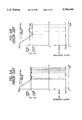
- FIG. 4A is a graph showing the change of SOC (State of Charge) during the cruising of the hybrid vehicle while FIG. 4B is a graph showing the electric power outputted from the generator, wherein a solid line represents the result according to the first embodiment of the present invention while a dotted line represents the result according to a comparative control;
- SOC State of Charge
- FIG. 5 is a graph showing the average power required when the hybrid vehicle is cruising
- FIGS. 6A and 6B are graphs showing the change of a SOC and the generated output in accordance with a conventional generator control system for a hybrid vehicle;
- FIG. 7 is a block diagram showing an overall arrangement of a generator control system incorporated in a parallel hybrid vehicle in accordance with a second embodiment of the present invention.
- FIG. 8 is a flow chart illustrating the operation of an engine output controller of ECU shown in FIG. 7;
- FIG. 9 is a graph illustrating an optimum engine operating region.
- FIG. 1 is a view showing an overall arrangement of a generator control system incorporated in a series hybrid vehicle in accordance with a first embodiment of the present invention, wherein the generator is directly connected to and driven by an internal combustion engine.
- a hybrid vehicle generally comprises, as a driving source of the vehicle, an electric motor 10 whose capacity or total number is determined in accordance with the specifications of each vehicle. For the purpose of simplifying the explanation, only one electric motor 10 is shown in the drawing.
- the electric motor 10 which is either a DC motor or an AC motor, has an output shaft 10a connected linked in a driving relationship to vehicle wheels 90 through a conventional driving mechanism including a transmission 70 and a differential mechanism 80.
- the electric motor 10 is electrically connected to a battery 20 via an inverter 50.
- the inverter 50 is operated by an electronic control unit (ECU) 60.
- the battery 20 supplies the electric motor 10 with electric power through this inverter 50, so that the hybrid vehicle is driven by the electric motor 10.
- electric motor 10 has a function of generating electric power, too. Utilizing regenerative braking during deceleration of vehicle, electric motor 10 generates regenerative electric power and utilizes the regenerated power to charge up battery 20.
- the battery 20 is equipped with a battery capacity sensor 21 detecting an integrating current value, which is a parameter representing the state of charge (SOC) of battery 20.
- the vehicle comprises an internal combustion engine 40 which is directly connected in a driving relation to a generator 30.
- the internal combustion engine 40 will be driven at a WOT (wide open throttle) condition, wherein the output of internal combustion engine 40 is controlled by the amount of fuel injected by an fuel injection valve while the throttle (not shown) is maintained at a wholly opened position.
- WOT wide open throttle
- the internal combustion engine 40 of the first embodiment has a limited output range wherein the output of internal combustion engine 40 has a one-to-one relationship with a rotational speed thereof.
- the generator 30, which is preferably a high efficient generator, is driven by internal combustion engine 40 and generates electric power which is variable in response to the rotational speed of internal combustion engine 40.
- the electric motor 10 can be driven by electric power generated by generator 30 or by electric power stored in battery 20. When generator 30 generates electrical power excessively, residual electric power is used to charge battery 20 through inverted 50.
- Inverter 50 is interposed among electric motor 10, battery 20 and generator 30 so as to be electrically connectable with each of them, and is controlled by ECU 60 so as to establish or release an electrical connection between each two elements of electric motor 10, battery 20 and generator 30, and also to adjust an electric value in the power supply from one element to a corresponding element.
- ECU 60 inputting detection data from sensors and controlling various components of the hybrid vehicle, comprises a memory 62 storing later-described control programs and various data used for computations, and interface circuits sending out control signals to the components of the hybrid vehicle or receiving signals from the same or sensors.
- ECU 60 comprises a generator output controller 61 which receives detection signals from battery capacitor sensor 21 and performs a fuzzy control of an output of generator 30 in accordance with the state of charge (SOC) itself of battery 20 and the variation of SOC.
- SOC state of charge
- FIG. 2 is a flow chart illustrating the operation of generator output controller 61 of ECU 60.
- FIG. 3 is one example showing a three-dimensional data map used for obtaining a command variation amount ⁇ W in the calculation of target power output "W".
- step S100 after the routine is started upon a start-up operation of the hybrid vehicle, generator output controller 61 detects the state of charge (SOC) of battery 20 together with its variation ⁇ SOC every 30 seconds based on the signals sent from battery capacity sensor 21.
- SOC state of charge
- step S101 generator output controller 61 calculates the command variation amount ⁇ W using SOC and ⁇ SOC as parameters of the following function:
- command variation amount ⁇ W is expressed in the form of a three-dimensional data map in relation to SOC and ⁇ SOC.
- the data of this map are determined in accordance with the required performance of the vehicle in the design of the control system.
- FIG. 3 illustrates the rule for the fuzzy control, according to which
- the target value for SOC control is set to 60%, taking account of the experimental result that the charging efficiency of the battery was worsened when SOC is 70% or more.
- command variation amount ⁇ W takes +1 (kw) when SOC is 70% and ⁇ SOC is -5%, and takes -4 (kw) for the same SOC when ⁇ SOC is changed to 0%, as indicated by small circles in the drawing.
- command variation amount ⁇ W can be given by the following equation:
- generator output controller 61 calculates the target power output "W" using the following formula:
- step S104 generator output controller 61 drives internal combustion engine 40 so that the target power output "W” can be obtained from generator 30.
- generator output controller 61 makes a judgement in step S105 as to whether the vehicle has finished the cruising. If the vehicle is still running ("No” in the step S105), the control flow returns to step S100 and repeats the steps S100 through S105. If the vehicle is stopped ("YES" in the step S105), this routine is ended.
- FIG. 4A shows the change of SOC during the cruising of the hybrid vehicle
- FIG. 4B shows the electric power outputted from the generator, wherein a solid line represents the result according to the generator output control of the present invention while a dotted line represents the result according to a comparative control based on the required power.
- the generator is subjected to a large variation or other fluctuation of power output.
- emission of exhaust gas tends to worsened when the engine speed is largely varied or fluctuated in this manner.
- SOC tends to be gradually decreased and offset from the target value.
- the variation or fluctuation of the power output of the generator can be suppressed within a small range and the SOC is almost equalized to the target value without causing undesirable deviation -or offset, because the generator output is controlled by taking account of both the magnitude of the SOC and the variation of the same. More specifically, in calculating the target power output "W", the command variation amount ⁇ W is always determined based on the SOC and ⁇ SOC.
- FIG. 7 shows an overall arrangement of a generator control system incorporated in a parallel hybrid vehicle in accordance with a second embodiment of the present invention.
- An internal combustion engine 400 serving as a main driving power source for the hybrid vehicle, is connected through a clutch 700 to an input shaft 100b of electric motor/generator 100 serving as a sub driving power source for the hybrid vehicle.
- the electric motor/generator has an output shaft 100a connected and linked in a driving relation to vehicle wheels 900 through a conventional driving mechanism including a transmission 800 and a differential mechanism 850. Namely, the speed of a rotational driving force of internal combustion engine 400 or motor/generator 100 is changed by transmission 800 and transmitted to vehicle wheels 900 via differential mechanism 850.
- the motor/generator 100 has functions both as of an electric motor and a generator. More specifically, when the motor/generator 100 acts as an electric motor, it generates an output torque in accordance with an exciting current variably controlled by an exciting current control signal. On the other hand, when the motor/generator 100 acts as a generator, it generates a regenerative torque in a regenerative braking during deceleration of the hybrid vehicle.
- the motor/generator 100 is electrically connected to a high-voltage battery 200 supplying approximately 100 volts through an inverter 500.
- the battery 200 is equipped with a battery capacity sensor 201 detecting an integrating current value which is a parameter representing the state of charge (SOC) of battery 200.
- Inverter 500 interposed between motor/generator 100 and battery 200 so as to be electrically connectable with each of them, is controlled by ECU 600 so as to establish or release the electrical connection between motor/generator 100 and battery 200, and also to adjust an electric value in the power supply from one element to the other element.
- ECU 600 is connected to plural sensors which cooperatively detect the vehicle operating conditions including the amounts an accelerator pedal and a brake pedal are depressed and a vehicle speed.
- ECU 600 controls an output of internal combustion engine 400 by generating a fuel injection control signal and an ignition timing control signal in accordance with the vehicle operating conditions detected by these sensors.
- ECU 600 receives a signal representing the state of charge (SOC) of battery 200 from battery capacity sensor 201, and adjusts an engine output in accordance with the detection values of the SOC and the variation of the same.
- SOC state of charge
- ECU 600 always generates a function switching signal for selecting either the motor function or the generator function, and a duty signal representing a torque (i.e. a motor output torque or a generator regenerative torque) required for motor/generator 100.
- the function switch signal and duty signal are supplied to inverter 500 so that the state of charge of battery 200 is maintained at a constant state.
- ECU 600 comprises a memory 601 storing later-described control programs and various data used for computations, and interface circuits sending out control signals to the components of the hybrid vehicle or receiving signals from the same or sensors.
- ECU 600 comprises an engine output controller 610, a function switching controller 620 for selecting the function of motor/generator 100, and a clutch controller 630 for engaging or disengaging the input and output shafts of clutch 700.
- FIG. 8 shows a flow chart illustrating the operation of each of engine output controller 610, motor/generator function switching controller 620 and clutch controller 630.
- step S200 after the routine is started upon a start-up operation of the hybrid vehicle, engine output controller 610 calculates a required output "P" every 0.1 second.
- the required output "P" is determined based on various detection signals representing vehicle operating conditions such as the depressing amounts of the accelerator pedal and the brake pedal are depressed or the vehicle speed.
- engine output controller 610 detects the state of charge (SOC) of battery 200 together with its variation ⁇ SOC every 30 seconds based on the signals sent from battery capacity sensor 201.
- SOC state of charge
- step S201 a judgement is made as to whether the required output "P" is positive or negative.
- motor/generator function switching controller 620 generates a signal for selecting the generator function.
- ECU 600 controls inverter 500 so as to optimally perform the regenerative braking operation.
- the clutch controller 630 generates a signal for disengaging the input and output shafts of clutch 700 and sends the signal to clutch 700.
- the clutch controller 630 With the disengagement of clutch 700, internal combustion engine 400 is completely separated from motor/generator 100. Thus, it becomes possible to eliminate any motoring load loss caused by internal combustion engine 400, thereby resulting in a high efficient recovery of regenerative energy in the generation by the motor/generator 100.
- the engagement of clutch 700 is carried out after the rotational speed of internal combustion engine 400 (i.e. the rotational speed of the input shaft of clutch. 700) is adjusted to be nearly equal to the rotational speed of motor/generator 100 (i.e. the rotational speed of the output shaft of clutch 700).
- the parallel hybrid vehicle usually starts up with a driving force of an associated electric motor and travels until it reaches an ordinary running condition. Then, after the vehicle running condition is stabilized, the input and output shafts of clutch 700 are engaged with each other to directly transmit the rotational output of internal combustion engine 400 to motor/generator 100, thereby driving the hybrid vehicle by the powerful driving force of internal combustion engine 400.
- the clutch 700 is selectively engaged or disengaged by clutch controller 630 so as to engage and disengage internal combustion engine 400 with and from motor/generator 100 in accordance with various running conditions of the hybrid vehicle.
- the engine output controller 610 calculates the engine output correction amount ⁇ P using the state of charge (SOC) of battery 200 and the variation of SOC (i.e. ⁇ SOC) as parameters of the following function:
- the function defining ⁇ P will be explained in the same manner as the function ⁇ W of the first embodiment with reference to FIG. 3. Namely, the data map shown in FIG. 3 is not limited to the first embodiment, although it was used for obtaining the command variation amount ⁇ W in the calculation of the target power output "W".
- FIG. 3 is used for obtaining the engine output correction amount ⁇ P in the calculation of target engine output "P0" in this second embodiment.
- engine output correction amount ⁇ P (in the parentheses) is expressed in the form of a three-dimensional data map in relation to SOC and ⁇ SOC. The data of this map are determined in accordance with the required performance of the vehicle in the design of the control system.
- the map shown in FIG. 3 illustrates the rule for the fuzzy control, according to which:
- the target value for SOC control is set to 60%, taking account of the experimental result that the charging efficiency of the battery was worsened when the SOC is 70% or more.
- engine output correction amount ⁇ P takes +1 (kw) when SOC is 70% and ⁇ SOC is -5%, and takes -4 (kw) for the same SOC when ⁇ SOC is changed to 0%, as indicated by the small circles in the drawing.
- engine output correction amount ⁇ P can be given by the following equation:
- step S204 engine output controller 610 calculates the target engine output "P0" based on the following formula:
- the optimum fuel economy region of the internal combustion engine shown in FIG. 9 is taken into consideration.
- the internal combustion engine 400 has the optimum fuel economy region of 240 g/kWh at the engine rotational speed of nearly 3 ⁇ 10 3 rpm with the net mean effective pressure of nearly 1.0 MPa.
- the actual engine operating region is depicted by a solid line connecting an upper limit and a lower limit.
- the maximum effective pressure exists beyond the engine operating region, and the engine output at the same engine speed increases with increasing net mean effective pressure.
- step S206 engine output controller 610 generates the fuel injection control signal and the ignition timing control signal so that internal combustion engine 400 can produce the target engine output "P0".
- step S207 a judgement is made as to whether target engine output "P0" is larger than the required engine output "P". If target engine output "P0" is equal to or smaller than the required engine output "P" (i.e. "NO” in the step S207), motor/generator function switching controller 620 generates a signal selecting the motor function and ECU 600 controls the motor/generator 100 to produce output (P-P0) which corresponds to a shortage to the presently required engine output "P".
- motor/generator function switching controller 620 generates a signal selecting the generator function and ECU 600 controls the motor/generator 100 to regenerate or recover output (P0-P) which corresponds to a surplus to the presently required engine output "P".
- step S210 After finishing the control of motor/generator 100, engine output controller 610 makes a judgement in step S210 as to whether the vehicle has finished the cruising. If the vehicle is still running ("NO" in the step S210), the control flow returns to step S200 and repeats the steps S200 through S210. If the vehicle is stopped ("YES" in the step S210), this routine is ended.
Landscapes
- Engineering & Computer Science (AREA)
- Transportation (AREA)
- Mechanical Engineering (AREA)
- Chemical & Material Sciences (AREA)
- Combustion & Propulsion (AREA)
- Sustainable Development (AREA)
- Life Sciences & Earth Sciences (AREA)
- Sustainable Energy (AREA)
- Power Engineering (AREA)
- Automation & Control Theory (AREA)
- Hybrid Electric Vehicles (AREA)
- Electric Propulsion And Braking For Vehicles (AREA)
- Control Of Charge By Means Of Generators (AREA)
- Charge And Discharge Circuits For Batteries Or The Like (AREA)
- Tests Of Electric Status Of Batteries (AREA)
Abstract
A series hybrid vehicle comprises a generator 30 driven by an internal combustion engine 40, a battery 20 chargeable by generator 30, an electric motor 10 rotated by electric power of generator 30 and battery 20. A parallel hybrid vehicle comprises. a battery 200 chargeable by an electric motor 100, and selectively uses an internal combustion engine 400 and electric motor 100 as driving source for driving vehicle wheels 900. In these -hybrid vehicles, there is provided a sensor 21 or 201 for detecting the state of charge (SOC) of battery 20 or 200. An output of generator 30 or internal combustion engine 400 is controlled based on each the SOC and a variation the SOC.
Description
1. Field of the Invention
This invention relates to a hybrid vehicle driven by two driving sources, such as a combination of an electric motor supplied with electric power from a battery and an internal combustion engine using fuel such as gasoline or light oil. More particularly, the invention relates to a generator control system for hybrid vehicles capable of providing an extended cruising distance without losing the benefits of an electric car, suppressing harmful emission during the rapid acceleration, and optimizing energy loss during the charging operation of the battery.
2. Related Art
Electric cars driven by motors are advantageous, when compared with the normal vehicles driven by engines, in that electric cars are so clean in exhaust gas emission as to cause no air pollution. Also, and in that noises are extremely small and the drivability, such as response in acceleration and deceleration, is excellent. On the other hand, because of the nature of the electric cars, the cruising distance is short due to the poor capacity of the batteries presently available present days, and the energy cost per unit travelling distance travelled is still expensive.
To eliminate the weakness of electric cars and enhance their advantages, there have been proposed various hybrid vehicles driven chiefly by a combination of an electric motor which is supplied electric power from batteries and an internal combustion engine using fuel such as gasoline or light oil.
The hybrid vehicles are roughly divided into two types. One of them is a series hybrid vehicle (SHV) which uses the electric motor as a single driving source for driving the wheels of the vehicle and uses the internal combustion engine as a source for rotating a generator for charging the battery. The other is a parallel hybrid vehicle (PHV) which selectively or alternately uses the motor and the internal combustion engine as a driving source for driving the wheels of the vehicle in accordance with travelling conditions of the vehicle.
According to the series hybrid vehicle, the internal combustion engine is controlled in such a manner that the generator directly connected to the engine generates enough electric power to charge the battery up to a predetermined SOC (State of Charge) level, while reducing the amount of exhaust gas as much as possible. In this case, the internal combustion engine is usually driven at a constant speed in order to reduce the amount of exhaust gas emitted from the engine.
FIG. 5 shows one example showing the average power required when the series hybrid vehicle is travelling.
FIGS. 6A and 6B are graphs showing the change of SOC and the generated output in accordance with a conventional generator control system for the hybrid vehicle.
In general, the charging operation of batteries is inherently subjected to significant energy loss due to generation of heat. To eliminate such energy loss, there is proposed a method for driving the series hybrid vehicle accompanied with a representative power consumption shown in FIG. 5. According to this method, the SOC control range (the SOC zone defined by upper and lower limits) is narrowed as shown in FIG. 6A. This control method is advantageous in that the energy loss can be minimized because a charging amount in each charging operation is small.
In this case, the hybrid vehicle is chiefly driven by the generator. Electric power of the battery is occasionally used to supplement or compensate for the shortage of electric power generated from the generator.
A problem of such a control method is that the generator needs to be so frequently activated or deactivated that the generated power is repetitively fluctuated between the predetermined set value and the idle value. In other words, the operating condition of the internal combustion engine is so rapidly and frequently varied that the exhaust gas emission is fairly deteriorated.
Meanwhile, as shown in FIG. 6B, it is possible to drive the hybrid vehicle with an enlarged SOC control range. This method is advantageous in that the fluctuation of the engine operating condition can be suppressed. However, as described above, the energy loss increases with increasing charging amount in each charging operation of the battery.
On the other hand, among parallel hybrid vehicles, there is known a parallel hybrid vehicle equipped with a motor/generator having functions of both a motor and a generator so as to occasionally charge the battery.
In the charging operation of batteries used for the above-described hybrid vehicles, the generator is usually rotated by the internal combustion engine in such a manner that the residual capacity of the battery is maintained in an allowable or preferable range defined by predetermined upper and lower limits. Thus, preventing the batteries are prevented from being excessively charged or discharged for an extended battery life, and a motor driving control is realized using the batteries being adequately charged.
For the series hybrid vehicles the, charging of batteries is immediately started upon each start-up of the associated internal combustion engine. In this case, the internal combustion engine is driven at the optimum fuel economy rate point (refer to FIG. 9) so as to cause the generator to produce a constant electric power. On the other hand, for the parallel hybrid vehicles, the internal combustion engine is driven within a predetermined region having the optimum fuel economy rate (refer to FIG. 9) based on the engine speed determined by the vehicle speed. The charging of batteries is performed by utilizing the surplus of the electric power generated by the generator.
According to Unexamined Japanese patent application No. HEI 6-197406, published in 1994, an average consumption of electric power of a hybrid vehicle is obtained to set a generation start point at a relatively higher value when the obtained average consumption electric power is relatively large, so that the charging operation of the battery can be started at an earlier time. Thus, the SOC is prevented from being excessively lowered even when the battery is subjected to a large load.
However, when the hybrid vehicle is abruptly accelerated, there is the possibility that the hybrid vehicle may be suffering from a shortage of electric power because the output of the engine-driven generator remains the same due to the engine rotational speed being maintained at a constant value irrespective of such an acceleration. In this case, it is generally necessary to use the electric energy stored in the battery. If such an acceleration is continued for a long time, it is feared that the energy stored in the battery will be so excessively consumed that the motor is no longer supplied with sufficient electric current, leading to the deterioration of the driving performance of the hybrid vehicle.
According to Unexamined Japanese patent application No. HEI 5-328525, published in 1993, a plurality of parameters are sensed to judge the vehicle driving conditions so as to drive the engine within a specific operating region where the fuel consumption of the engine is small. Namely, to control the electric power produced by the generator, the rotational speed of the internal combustion engine is varied in accordance with the driving conditions of the series hybrid vehicle.
However, controlling the output of the engine-driven generator solely in accordance with the vehicle driving conditions is not desirable because the fuel consumption in the engine is increased, or exhaust gas emission is worsened due to large variation or fluctuation of the engine speed.
On the other hand, if the maximum power output of the engine-driven generator is limited to suppress fuel consumption in the engine or prevent the exhaust gas emission from worsening, the engine-driven generator may encounter a shortage of the power output. Such a shortage of electric power can be compensated by the energy stored in the battery. However, simply relying on the stored energy in the battery may result in the fatal lack of residual capacity of the battery and substantially reduces the cruising distance of the hybrid vehicle.
When the battery is frequently subjected to excessive loads, the life of the battery will be fairly shortened.
Furthermore, the reduction of the cruising distance may be induced from the energy loss caused in the charging operation of the battery. For example, when the surplus of electric power produced by the generator is stored during a constant-speed cruising condition.
Moreover, according to the engine operating method of the above-described parallel hybrid vehicle, there is a problem that the driving feeling is worsened at the switching (each start and each end) timing in the battery charging operation.
Still further, charging the battery is inherently subjected to a generation of heat, thereby causing energy loss. This kind of energy loss increases with increasing charging power.
In the above-described engine operating method (the method of driving the internal combustion engine in the optimum fuel economy rate region in accordance with the engine speed as determined by the vehicle speed), the engine is always driven in the optimum fuel economy rate region regardless of change of battery conditions. Hence, the obtained charging power will be fairly large compared with the required power. This will increase the amount of the above-described energy loss.
Accordingly, in view of above-described problems encountered in the related art, a principal object of the present invention is to provide a generator control system for series/parallel hybrid vehicles capable of maintaining the battery residual capacity within an allowable or desirable range, and optimizing the energy loss during the battery charging operation, without worsening exhaust gas emission during acceleration.
In order to accomplish this and other related objects, a first aspect of the present invention provides a generator control system for hybrid vehicles including a generator driven by an internal combustion engine. A battery is chargeable by the generator, and an electric motor is driven by electric power supplied from the generator and the battery; state-of-charge detecting means detects a state of charge of the battery. A generated output control means for controls an electrical output of the generator based on not only the state of charge of the battery but also a variation of the state of charge.
According to the above-described control system, the state of charge of the battery can be always maintained within a preferable range without causing excessive charge and excessive discharge, thereby preventing the performance of the battery from deteriorating. Furthermore, it becomes possible to optimize the energy loss during the charging operation of the battery, thereby enabling the hybrid vehicle to cruise an extended distance. Moreover, the capability of suppressing the variation or fluctuation of generated output makes it possible to stabilize the operation of the internal combustion engine, thereby preventing exhaust gas emission from worsening.
In the above-described generator control system for hybrid vehicles, it is preferable that the generated output control means performs a fuzzy control in such a manner the electrical output is maintained when a residual capacity of the battery is large and the battery is discharging, decreased when the residual capacity of the battery is large and the battery is charging, increased when the residual capacity of the battery is small and the battery is discharging, and maintained when the residual capacity of the battery is small and the battery is charging.
According to features in the preferred embodiment, the electric motor has a function of generating electric power to charge the battery by utilizing a regenerative braking in a deceleration of a hybrid vehicle. The control means comprises a memory for storing control commands used for the computation of a target power output of the generator. The memory stores the control commands in relation to the state of charge and the variation of the state of charge, preferably in the form of a three-dimensional data map. Alternatively, for obtaining the control command used for the computation of the target power output of the generator, the control means can use an equation defined by the state of charge and the variation of the state of charge.
According to further features in the preferred embodiment, there is provided a hybrid vehicle including an internal combustion engine. A generator is connected to and driven by the internal combustion engine. An inverter electrically connected to the generator and, a battery is chargeable by the generator through the inverter. An electric motor is driven by electric power supplied from the generator and the battery through the inverter, the electric motor acting as a driving source for driving vehicle wheels. A state-of-charge detecting means detects a state of charge of the battery. A control means controls an electrical output of the generator based on not only the state of charge of the battery but also a variation of the state of charge.
The internal combustion engine is exclusively used for rotating the generator. The electric motor has an output shaft connected to the vehicle wheels through a driving mechanism including a transmission and a differential mechanism. The internal combustion engine is driven at a wide open throttle condition, so that an output of the internal combustion engine is controlled by an amount of fuel supplied by a fuel supply device while maintaining a throttle at a wholly opened position. The internal combustion engine is controlled within a limited output range so that an output of the internal combustion engine has a one-to-one relationship with a rotational speed of the internal combustion engine. The inverter charges the battery by utilizing residual electric power when the generator generates excessive electric power.
Furthermore, a second aspect of the present invention provides a generator control system for hybrid vehicles including an electric motor having both motor and generator functions so as to form one driving source for driving wheels of a hybrid vehicle and also serve as a generating source for generating electric power. An internal combustion engine forms another driving source for driving the wheels of the hybrid vehicle. A clutch is interposed between the electric motor and the internal combustion engine for selectively engaging and disengaging the internal combustion engine with and from the electric motor. A battery is chargeable by the electric motor, and a state-of-charge detecting means detects a state of charge of the battery. A engine output control means for controls an output of the internal combustion engine and -a residual capacity of the battery based on not only the state of charge of the battery but also a variation of the state of charge. A motor function switching means switches the electric motor between the motor function and the generator function on the basis of the control by the engine output control means. A clutch controlling means engages and disengages the internal combustion engine with and from the electric motor on the basis of the control by the engine output control means.
According to the above-described second aspect of the control system, the state of charge of the battery can be always maintained within a preferable range without causing excessive charge and excessive discharge, thereby preventing the performance of the battery from deteriorating. Furthermore, it becomes possible to optimize the energy loss during the charging operation of the battery, thereby enabling the hybrid vehicle to cruise for an extended distance. Moreover, the capability of suppressing the variation or fluctuation of generated output makes it possible to stabilize the operation of the internal combustion engine, thereby preventing exhaust gas emission from worsening.
In the above-described second aspect of the generator control system for hybrid vehicles, it is desirable that the engine output control means performs a fuzzy control in such a manner that an engine operating region is maintained when a residual capacity of the battery is large and the battery is discharging, shifted to a lower output region when the residual capacity of the battery is large and the battery is charging, shifted to a larger output region when the residual capacity of the battery is small and the battery is discharging, and maintained when the residual capacity of the battery is small and the battery is charging.
According to features in the preferred embodiment, the engine output controls means control the output of the internal combustion engine so as to maintain the state of charge of the battery at a predetermined constant level. The electric motor generates electric power to charge the battery by utilizing a regenerative braking in a deceleration of the hybrid vehicle. The engine output control means is associated with a memory for storing control commands used for the computation of a target output of the internal combustion engine. The memory stores the control commands in relation to the state of charge and the variation of the state of charge, preferably in the form of a three-dimensional data map. Alternatively, for obtaining the control command used for computation of the target output of the internal combustion engine, the control means uses an equation defined by the state of charge and the variation of the state of charge.
According to further features of the preferred embodiment, there is provided a hybrid vehicle including an electric motor having both motor and generator functions so as to form one driving source for driving vehicle wheels and also serve as a generating source for generating electric power. An internal combustion engine forms another driving source for driving the wheels of the hybrid vehicle. A clutch interposed between the electric motor and the internal combustion engine selectively engages and disengages the internal combustion engine with and from an input shaft of the electric motor. An inverter is electrically connected to the electric motor and a battery is chargeable by the electric motor through the inverter. Vehicle wheels are connected to an output shaft of the electric motor through a driving mechanism. A state-of-charge detecting means detects a state of charge of the battery. An engine output control means controls an output of the internal combustion engine and a residual capacity of the battery based on not only the state of charge of the battery but also a variation of the state of charge. A motor function switching means switches the electric motor between the motor function and the generator function on the basis of the control by the engine output control means. A clutch controlling means for engages and disengages the internal combustion engine with and from the electric motor on the basis of the control by the engine output control means.
Moreover, another aspect of the present invention provides several methods for controlling the above-described hybrid vehicle systems.
The above and other objects, features and advantages of the present invention will become more apparent from the following detailed description which is to be read in conjunction with the accompanying drawings, in which:
FIG. 1 is a block diagram showing an overall arrangement of a generator control system incorporated in a series hybrid vehicle in accordance with a first embodiment of the present invention;
FIG. 2 is a flow chart illustrating the operation of a generator output controller of an ECU shown in FIG. 1;
FIG. 3 is one example showing a three-dimensional data map used for calculating a command variation amount in the calculation of the target generator power output in the first embodiment, or an engine output correction amount in the calculation of the target engine output in a second embodiment;
FIG. 4A is a graph showing the change of SOC (State of Charge) during the cruising of the hybrid vehicle while FIG. 4B is a graph showing the electric power outputted from the generator, wherein a solid line represents the result according to the first embodiment of the present invention while a dotted line represents the result according to a comparative control;
FIG. 5 is a graph showing the average power required when the hybrid vehicle is cruising;
FIGS. 6A and 6B are graphs showing the change of a SOC and the generated output in accordance with a conventional generator control system for a hybrid vehicle;
FIG. 7 is a block diagram showing an overall arrangement of a generator control system incorporated in a parallel hybrid vehicle in accordance with a second embodiment of the present invention;
FIG. 8 is a flow chart illustrating the operation of an engine output controller of ECU shown in FIG. 7; and
FIG. 9 is a graph illustrating an optimum engine operating region.
Preferred embodiments of the present invention will be explained in greater detail hereinafter, with reference to the accompanying drawings.
FIG. 1 is a view showing an overall arrangement of a generator control system incorporated in a series hybrid vehicle in accordance with a first embodiment of the present invention, wherein the generator is directly connected to and driven by an internal combustion engine. A hybrid vehicle generally comprises, as a driving source of the vehicle, an electric motor 10 whose capacity or total number is determined in accordance with the specifications of each vehicle. For the purpose of simplifying the explanation, only one electric motor 10 is shown in the drawing.
The electric motor 10, which is either a DC motor or an AC motor, has an output shaft 10a connected linked in a driving relationship to vehicle wheels 90 through a conventional driving mechanism including a transmission 70 and a differential mechanism 80.
The electric motor 10 is electrically connected to a battery 20 via an inverter 50. The inverter 50 is operated by an electronic control unit (ECU) 60. The battery 20 supplies the electric motor 10 with electric power through this inverter 50, so that the hybrid vehicle is driven by the electric motor 10.
Furthermore, electric motor 10 has a function of generating electric power, too. Utilizing regenerative braking during deceleration of vehicle, electric motor 10 generates regenerative electric power and utilizes the regenerated power to charge up battery 20. The battery 20 is equipped with a battery capacity sensor 21 detecting an integrating current value, which is a parameter representing the state of charge (SOC) of battery 20.
The vehicle comprises an internal combustion engine 40 which is directly connected in a driving relation to a generator 30. In view of driving efficiency of internal combustion engine 40, the internal combustion engine 40 will be driven at a WOT (wide open throttle) condition, wherein the output of internal combustion engine 40 is controlled by the amount of fuel injected by an fuel injection valve while the throttle (not shown) is maintained at a wholly opened position.
To realize the high efficient drive, the internal combustion engine 40 of the first embodiment has a limited output range wherein the output of internal combustion engine 40 has a one-to-one relationship with a rotational speed thereof.
The generator 30, which is preferably a high efficient generator, is driven by internal combustion engine 40 and generates electric power which is variable in response to the rotational speed of internal combustion engine 40.
The electric motor 10 can be driven by electric power generated by generator 30 or by electric power stored in battery 20. When generator 30 generates electrical power excessively, residual electric power is used to charge battery 20 through inverted 50.
In this first embodiment, ECU 60 comprises a generator output controller 61 which receives detection signals from battery capacitor sensor 21 and performs a fuzzy control of an output of generator 30 in accordance with the state of charge (SOC) itself of battery 20 and the variation of SOC.
FIG. 2 is a flow chart illustrating the operation of generator output controller 61 of ECU 60. FIG. 3 is one example showing a three-dimensional data map used for obtaining a command variation amount ΔW in the calculation of target power output "W".
In step S100, after the routine is started upon a start-up operation of the hybrid vehicle, generator output controller 61 detects the state of charge (SOC) of battery 20 together with its variation ΔSOC every 30 seconds based on the signals sent from battery capacity sensor 21.
In step S101, generator output controller 61 calculates the command variation amount ΔW using SOC and ΔSOC as parameters of the following function:
ΔW=f(SOC, ΔSOC ) (1).
As shown in FIG. 3, command variation amount ΔW is expressed in the form of a three-dimensional data map in relation to SOC and ΔSOC. The data of this map are determined in accordance with the required performance of the vehicle in the design of the control system.
More specifically, the. map shown in FIG. 3 illustrates the rule for the fuzzy control, according to which
(1) the target power output "W" is maintained when SOC is high and ΔSOC is a negative value;
(2) the target power output "W" is decreased when SOC is high and ΔSOC is a positive value;
(3) the target power output "W" is increased when SOC is low and ΔSOC is a negative value; and
(4) the target power output "W" is maintained when SOC is low and ΔSOC is a positive value.
In this first embodiment, the target value for SOC control is set to 60%, taking account of the experimental result that the charging efficiency of the battery was worsened when SOC is 70% or more.
With reference to FIG. 3, it will be understood that command variation amount ΔW takes +1 (kw) when SOC is 70% and ΔSOC is -5%, and takes -4 (kw) for the same SOC when ΔSOC is changed to 0%, as indicated by small circles in the drawing.
In this case, command variation amount ΔW can be given by the following equation:
ΔW=-0.4×SOC-ΔSOC+24.0, when -5.0 ≦ΔW≦5.0; ΔW=5.0, when ΔW>5.0; and ΔW=-5.0, when ΔW<-5.0 (1').
Returning to the flow chart of FIG. 2, in step S102, generator output controller 61 calculates the target power output "W" using the following formula:
W=W+ΔW (2).
In the next step S103, generator output controller 61 makes a judgement as to whether the newly obtained target power output "W" thus calculated in step S102 exceeds a predetermined maximum power output "Wmax". If the newly obtained target power output "W" exceeds the maximum power output "Wmax", the target power output "W" is reduced or corrected to the upper limit value "Wmax" (i.e. W=Wmax).
In the same step S103, generator output controller 61 makes another judgement as to whether the newly obtained target power output "W" calculated in step S102 is smaller than a predetermined minimum power output "Wmin". If the newly obtained target power output "W" is smaller than the minimum power output "Wmin", the target power output "W" is increased or corrected to the lower limit value "Wmin" (i.e. W=Wmin).
In determining maximum power output Wmax and minimum power output Wmin, the efficiency of the internal combustion engine and other factors should be taken into consideration.
Subsequently, in step S104, generator output controller 61 drives internal combustion engine 40 so that the target power output "W" can be obtained from generator 30. After finishing the output control of generator 30, generator output controller 61 makes a judgement in step S105 as to whether the vehicle has finished the cruising. If the vehicle is still running ("No" in the step S105), the control flow returns to step S100 and repeats the steps S100 through S105. If the vehicle is stopped ("YES" in the step S105), this routine is ended.
FIG. 4A shows the change of SOC during the cruising of the hybrid vehicle, while FIG. 4B shows the electric power outputted from the generator, wherein a solid line represents the result according to the generator output control of the present invention while a dotted line represents the result according to a comparative control based on the required power.
As understood from FIGS. 4A and 4B, according to the comparative control based on the required power, the generator is subjected to a large variation or other fluctuation of power output. In general, emission of exhaust gas tends to worsened when the engine speed is largely varied or fluctuated in this manner. Furthermore, as shown in FIG. 4A, SOC tends to be gradually decreased and offset from the target value.
On the other hand, according to the embodiment of the present invention, the variation or fluctuation of the power output of the generator can be suppressed within a small range and the SOC is almost equalized to the target value without causing undesirable deviation -or offset, because the generator output is controlled by taking account of both the magnitude of the SOC and the variation of the same. More specifically, in calculating the target power output "W", the command variation amount ΔW is always determined based on the SOC and ΔSOC.
Hereinafter, a second embodiment of the present invention will be explained with reference to FIGS. 7 through 9. FIG. 7 shows an overall arrangement of a generator control system incorporated in a parallel hybrid vehicle in accordance with a second embodiment of the present invention.
An internal combustion engine 400, serving as a main driving power source for the hybrid vehicle, is connected through a clutch 700 to an input shaft 100b of electric motor/generator 100 serving as a sub driving power source for the hybrid vehicle. The electric motor/generator has an output shaft 100a connected and linked in a driving relation to vehicle wheels 900 through a conventional driving mechanism including a transmission 800 and a differential mechanism 850. Namely, the speed of a rotational driving force of internal combustion engine 400 or motor/generator 100 is changed by transmission 800 and transmitted to vehicle wheels 900 via differential mechanism 850.
The motor/generator 100 has functions both as of an electric motor and a generator. More specifically, when the motor/generator 100 acts as an electric motor, it generates an output torque in accordance with an exciting current variably controlled by an exciting current control signal. On the other hand, when the motor/generator 100 acts as a generator, it generates a regenerative torque in a regenerative braking during deceleration of the hybrid vehicle.
The motor/generator 100 is electrically connected to a high-voltage battery 200 supplying approximately 100 volts through an inverter 500. The battery 200 is equipped with a battery capacity sensor 201 detecting an integrating current value which is a parameter representing the state of charge (SOC) of battery 200.
In this second embodiment, ECU 600 comprises an engine output controller 610, a function switching controller 620 for selecting the function of motor/generator 100, and a clutch controller 630 for engaging or disengaging the input and output shafts of clutch 700.
FIG. 8 shows a flow chart illustrating the operation of each of engine output controller 610, motor/generator function switching controller 620 and clutch controller 630.
In step S200, after the routine is started upon a start-up operation of the hybrid vehicle, engine output controller 610 calculates a required output "P" every 0.1 second. In this case, the required output "P" is determined based on various detection signals representing vehicle operating conditions such as the depressing amounts of the accelerator pedal and the brake pedal are depressed or the vehicle speed. In addition, in the same manner as the first embodiment, engine output controller 610 detects the state of charge (SOC) of battery 200 together with its variation ΔSOC every 30 seconds based on the signals sent from battery capacity sensor 201.
In step S201, a judgement is made as to whether the required output "P" is positive or negative. When the required output "P" is zero or negative (i.e. "NO" in the step S201), engine output controller 610 sets the target engine output "P0" to "0" (i.e. P0=0) in step S202. Then, motor/generator function switching controller 620 generates a signal for selecting the generator function. ECU 600 controls inverter 500 so as to optimally perform the regenerative braking operation.
Meanwhile, the clutch controller 630 generates a signal for disengaging the input and output shafts of clutch 700 and sends the signal to clutch 700. With the disengagement of clutch 700, internal combustion engine 400 is completely separated from motor/generator 100. Thus, it becomes possible to eliminate any motoring load loss caused by internal combustion engine 400, thereby resulting in a high efficient recovery of regenerative energy in the generation by the motor/generator 100.
In this second embodiment, the engagement of clutch 700 is carried out after the rotational speed of internal combustion engine 400 (i.e. the rotational speed of the input shaft of clutch. 700) is adjusted to be nearly equal to the rotational speed of motor/generator 100 (i.e. the rotational speed of the output shaft of clutch 700).
More specifically, the parallel hybrid vehicle usually starts up with a driving force of an associated electric motor and travels until it reaches an ordinary running condition. Then, after the vehicle running condition is stabilized, the input and output shafts of clutch 700 are engaged with each other to directly transmit the rotational output of internal combustion engine 400 to motor/generator 100, thereby driving the hybrid vehicle by the powerful driving force of internal combustion engine 400. However, according to the second embodiment of the present invention, the clutch 700 is selectively engaged or disengaged by clutch controller 630 so as to engage and disengage internal combustion engine 400 with and from motor/generator 100 in accordance with various running conditions of the hybrid vehicle.
It is desirable to engage the input and output shafts of clutch 700 to connect internal combustion engine 400 to motor/generator 100 when the hybrid vehicle is stopped and to cause motor/generator function switching controller 620 to select the motor function so that motor/generator 100 can be used as a starter in the start-up operation of internal combustion engine 400.
When the required output "P" is positive (i.e. "YES" in the step S201), the engine output controller 610 calculates the engine output correction amount ΔP using the state of charge (SOC) of battery 200 and the variation of SOC (i.e. ΔSOC) as parameters of the following function:
ΔP=f(SOC, ΔSOC) (3).
The function defining ΔP will be explained in the same manner as the function ΔW of the first embodiment with reference to FIG. 3. Namely, the data map shown in FIG. 3 is not limited to the first embodiment, although it was used for obtaining the command variation amount ΔW in the calculation of the target power output "W".
More specifically, FIG. 3 is used for obtaining the engine output correction amount ΔP in the calculation of target engine output "P0" in this second embodiment. As shown in FIG. 3, engine output correction amount ΔP (in the parentheses) is expressed in the form of a three-dimensional data map in relation to SOC and ΔSOC. The data of this map are determined in accordance with the required performance of the vehicle in the design of the control system.
More specifically, in the same manner as in the first embodiment, the map shown in FIG. 3 illustrates the rule for the fuzzy control, according to which:
(1) the engine output correction amount "ΔP" is maintained when the SOC is high and ΔSOC is a negative value;
(2) the engine output correction amount "ΔP" is decreased when the SOC is high and ΔSOC is a positive value;
(3) the engine output correction amount "ΔP" is increased when the SOC is low and ΔSOC is a negative value; and
(4) the engine output correction amount "ΔP" is maintained when the SOC is low and ΔSOC is a positive value.
In the second embodiment, the target value for SOC control is set to 60%, taking account of the experimental result that the charging efficiency of the battery was worsened when the SOC is 70% or more.
With reference to FIG. 3, it will be understood that engine output correction amount ΔP takes +1 (kw) when SOC is 70% and ΔSOC is -5%, and takes -4 (kw) for the same SOC when ΔSOC is changed to 0%, as indicated by the small circles in the drawing.
In this case, engine output correction amount ΔP can be given by the following equation:
ΔP=-0.4×SOC-ΔSOC+24.0, when -5.0 ≦ΔP≦5.0; ΔP=5.0, when ΔP>5.0; and ΔP=-5.0, when ΔP<-5.0 (3').
Returning to the flow chart of FIG. 8, in step S204, engine output controller 610 calculates the target engine output "P0" based on the following formula:
P0 =P+ΔP (4).
In step S205, engine output controller 610 makes a judgement as to whether the obtained target engine output "P0" thus calculated in step S204. exceeds the maximum engine output "Pmax". If the obtained target engine output "P0" exceeds the maximum engine output "Pmax", the target engine output "P0" is reduced or corrected to the upper limit value "Pmax" (i.e. P0=Pmax).
In the same step S205, engine output controller 610 makes another judgement as to whether the obtained target engine output "P0" calculated in step S204 is smaller than "0". If the obtained target engine output "P0" is smaller than "0", the target engine output "P0" is increased or corrected to "0" (i.e. P0=0).
In determining maximum engine output Pmax, the optimum fuel economy region of the internal combustion engine shown in FIG. 9 is taken into consideration. As shown by equi-fuel economy rate curves in FIG. 9, the internal combustion engine 400 has the optimum fuel economy region of 240 g/kWh at the engine rotational speed of nearly 3×10³ rpm with the net mean effective pressure of nearly 1.0 MPa. Thus, the actual engine operating region is depicted by a solid line connecting an upper limit and a lower limit. As shown in FIG. 9, the maximum effective pressure exists beyond the engine operating region, and the engine output at the same engine speed increases with increasing net mean effective pressure.
Subsequently, in step S206, engine output controller 610 generates the fuel injection control signal and the ignition timing control signal so that internal combustion engine 400 can produce the target engine output "P0".
Then, in step S207, a judgement is made as to whether target engine output "P0" is larger than the required engine output "P". If target engine output "P0" is equal to or smaller than the required engine output "P" (i.e. "NO" in the step S207), motor/generator function switching controller 620 generates a signal selecting the motor function and ECU 600 controls the motor/generator 100 to produce output (P-P0) which corresponds to a shortage to the presently required engine output "P".
On the other hand, if target engine output "P0" is larger than the required engine output "P" (i.e. "YES" in the step S207), motor/generator function switching controller 620 generates a signal selecting the generator function and ECU 600 controls the motor/generator 100 to regenerate or recover output (P0-P) which corresponds to a surplus to the presently required engine output "P".
After finishing the control of motor/generator 100, engine output controller 610 makes a judgement in step S210 as to whether the vehicle has finished the cruising. If the vehicle is still running ("NO" in the step S210), the control flow returns to step S200 and repeats the steps S200 through S210. If the vehicle is stopped ("YES" in the step S210), this routine is ended.
As this invention may be embodied in several forms without departing from the spirit of essential characteristics thereof, the present embodiments described are therefore intended to be only illustrative and not restrictive, since the scope of the invention is defined by the appended claims rather than by the description preceding them, and all changes that fall within metes and bounds of the claims, or equivalents of such metes and bounds, are therefore intended to be embraced by the claims.
Claims (45)
1. A generator control system for hybrid vehicles comprising:
a generator driven by an internal combustion engine;
a battery chargeable by said generator;
an electric motor driven by electric power supplied from said generator and said battery;
state-of-charge detecting means for detecting a state of charge of said battery at predetermined sampling intervals to obtain a present state-of-charge (SOC) of said battery and a variation (ΔSOC) of said state-of-charge of said battery during a predetermined time interval based on said present state-of-charge (SOC); and
control means for controlling an electrical output of said generator based on said present state-of-charge (SOC) and said variation (ΔSOC).
2. The generator control system for hybrid vehicles defined by claim 1, wherein said control means performs a fuzzy control in such a manner so that said electrical output of said generator is maintained when a residual capacity of said battery is large and said battery is discharging, decreased when said residual capacity of said battery is large and said battery is charging, increased when said residual capacity of said battery is small and said battery is discharging, and maintained when said residual capacity of said battery is small and said battery is charging.
3. The generator control system for hybrid vehicles defined by claim 1, wherein said electric motor generates electric power to charge said battery by utilizing a regenerative braking in a deceleration of a hybrid vehicle.
4. The generator control system for hybrid vehicles defined by claim 1, wherein said control means comprises a memory for storing control commands used for a computation of a target power output of said generator.
5. The generator control system for hybrid vehicles defined by claim 4, wherein said memory stores said control commands in relation to said present state-of-charge (SOC) and said variation (ΔSOC).
6. The generator control system for hybrid vehicles defined by claim 5, wherein said memory stores said control commands in the form of a three-dimensional data map.
7. The generator control system for hybrid vehicles defined by claim 1, wherein said control means uses an equation defined by said present state-of-charge (SOC) and said variation (ΔSOC) to obtain a control command used for a computation of a target power output of said generator.
8. The generator control system for hybrid vehicles defined by claim 1, wherein a judgment is made as to whether a sign of said variation (ΔSOC) is positive or negative, and said output of said generator is controlled in accordance with said sign of said variation (ΔSOC).
9. The generator control system for hybrid vehicles defined by claim 1, wherein a judgment is made as to whether a level of said present state-of-charge (SOC) is high or low relative to a reference level and whether a sign of said variation (ΔSOC) is positive or negative, and said output of said generator is controlled in accordance with said level of said present state-of-charge (SOC) and said sign of said variation (ΔSOC).
10. A hybrid vehicle comprising:
an internal combustion engine;
a generator connected to and driven by said internal combustion engine;
an inverter electrically connected to said generator;
a battery chargeable by said generator through said inverter;
an electric motor driven by electric power supplied from said generator and said battery through said inverter, said electric motor acting as a driving source for driving vehicle wheels;
state-of-charge detecting means for detecting a state of charge of said battery at predetermined sampling intervals to obtain a present state-of-charge (SOC) of said battery and a variation (ΔSOC) of the state-of-charge of said battery during a predetermined time interval based on said present state-of-charge (SOC); and
control means for controlling an electrical output of said generator based on said present state-of-charge (SOC) and said variation (ΔSOC).
11. The hybrid vehicle defined by claim 10, wherein said control means controls said internal combustion engine in such a manner so that said electrical output of said generator is maintained when a residual capacity of said battery is large and said battery is discharging, decreased when said residual capacity of said battery is large and said battery is charging, increased when said residual capacity of said battery is small and said battery is discharging, and maintained when said residual capacity of said battery is small and said battery is charging.
12. The hybrid vehicle defined by claim 10, wherein said internal combustion engine is exclusively used for rotating said generator.
13. The hybrid vehicle defined by claim 10, wherein said electric motor has an output shaft connected to said vehicle wheels through a driving mechanism including a transmission and a differential mechanism.
14. The hybrid vehicle defined by claim 10, wherein said electric motor generates electric power to charge said battery by utilizing a regenerative braking in a deceleration of said hybrid vehicle.
15. The hybrid vehicle defined by claim 10, wherein said internal combustion engine is driven at a wide open throttle condition, so that an output of said internal combustion engine is controlled by an amount of fuel supplied by a fuel supply device while maintaining a throttle at a wholly opened position.
16. The hybrid vehicle defined by claim 10, wherein said internal combustion engine is controlled within a limited output range so that an output of said internal combustion engine has a one-to-one relationship with a rotational speed of said internal combustion engine.
17. The hybrid vehicle defined by claim 10, wherein said inverter charges said battery by utilizing residual electric power when said generator generates excessive electric power.
18. The hybrid vehicle defined by claim 10, wherein said control means comprises a memory for storing control commands used for computing a target power output of said generator.
19. The hybrid vehicle defined by claim 18, wherein said memory stores said control commands in relation to said present state-of-charge (SOC) and said variation (ΔSOC).
20. The hybrid vehicle defined by claim 19, wherein said memory stores said control commands in the form of a three-dimensional data map.
21. The hybrid vehicle defined by claim 10, wherein said control means uses an equation defined by said present state-of-charge (SOC) and said variation (ΔSOC ) to obtain a control command used for a computation of a target power output of said generator.
22. A control system for hybrid vehicles comprising:
an electric motor, having both motor and generator functions to form one driving source for driving wheels of a hybrid vehicle and serve as a generating source for generating electric power;
an internal combustion engine forming another driving source for driving said wheels of said hybrid vehicle;
a clutch interposed between said electric motor and said internal combustion engine for selectively engaging and disengaging said internal combustion engine with and from said electric motor;
a battery chargeable by said electric motor;
state-of-charge detecting means for detecting a state of charge of said battery at predetermined sampling intervals to obtain a present state-of-charge (SOC) of said battery and a variation (ΔSOC) of the state-of-charge of said batter v during a predetermined time interval based on said present state-of-charge (SOC);
engine output control means for controlling an output of said internal combustion engine and a residual capacity of said battery based on said present state-of-charge (SOC) and said variation (ΔSOC);
motor function switching means for switching said electric motor between said motor function and said generator function on the basis of said control by said engine output control means; and
clutch controlling means for engaging and disengaging said internal combustion engine with and from said electric motor on the basis of said control by said engine output control means.
23. The control system for hybrid vehicles defined by claim 22, wherein said engine output control means performs a fuzzy control in such a manner so that an operating region of said internal combustion engine is maintained when said residual capacity of said battery is large and said battery is discharging, shifted to a lower output region when said residual capacity of said battery is large and said battery is charging, shifted to a larger output region when said residual capacity of said battery is small and said battery is discharging, and maintained when said residual capacity of said battery is small and said battery is charging.
24. The control system for hybrid vehicles defined by claim 22, wherein said engine output control means controls the output of said internal combustion engine so as to maintain said present state-of-charge (SOC) of said battery at a predetermined constant level.
25. The control system for hybrid vehicles defined by claim 22, wherein said electric motor generates electric power to charge said battery by utilizing a regenerative braking in a deceleration of said hybrid vehicle.
26. The control system for hybrid vehicles defined by claim 22, wherein said engine output control means is associated with a memory for storing control commands used for a computation of a target output of said internal combustion engine.
27. The control system for hybrid vehicles defined by claim 26, wherein said memory stores said control commands in relation to said present state-of-charge (SOC) and said variation (ΔSOC).
28. The control system for hybrid vehicles defined by claim 27, wherein said memory stores said control commands in the form of a three-dimensional data map.
29. The control system for hybrid vehicles defined by claim 22, wherein said control means uses an equation defined by said present state-of-charge (SOC) and said variation (ΔSOC) to obtain a control command used for a computation of a target output of said internal combustion engine.
30. A hybrid vehicle comprising:
an electric motor, having both motor and generator functions to form one driving source for driving vehicle wheels of said hybrid vehicle and serve as a generating source for generating electric power;
an internal combustion engine forming another driving source for driving said wheels of said hybrid vehicle;
a clutch interposed between said electric motor and said internal combustion engine for selectively engaging and disengaging said internal combustion engine with and from an input shaft of said electric motor;
an inverter electrically connected to said electric motor;
a battery chargeable by said electric motor through said inverter;
wherein said vehicle wheels are connected to an output shaft of said electric motor through a driving mechanism;
state-of-charge detecting means for detecting a state of charge of said battery at predetermined sampling intervals to obtain a present state-of-charge (SOC) of said battery and a variation (ΔSOC) of the state of charge of said battery during a predetermined time interval based on said present state-of-charge (SOC);
engine output control means for controlling an output of said internal combustion engine and a residual capacity of said battery based on said present state-of-charge (SOC) and said variation (ΔSOC);
motor function switching means for switching said electric motor between said motor function and said generator function on the basis of said control by said engine output control means; and
clutch controlling means for engaging and disengaging said internal combustion engine with and from said electric motor on the basis of said control by said engine output control means.
31. The hybrid vehicle defined by claim 30, wherein said engine output control means controls said internal combustion engine in such a manner so that an engine operating region is maintained when said residual capacity of said battery is large and said battery is discharging, shifted to a lower output region when said residual capacity of said battery is large and said battery is charging, shifted to a larger output region when said residual capacity of said battery is small and said battery is discharging, and maintained when said residual capacity of said battery is small and said battery is charging.
32. The hybrid vehicle defined by claim 30, wherein said engine output control means controls said internal combustion engine so as to maintain said present state-of-charge (SOC) of said battery at a predetermined constant level.
33. The hybrid vehicle defined by claim 30, wherein said electric motor generates electric power to charge said battery by utilizing a regenerative braking in a deceleration of said hybrid vehicle.
34. The hybrid vehicle defined by claim 30, wherein said inverter charges said battery by utilizing residual electric power when said electric motor generates excessive electric power.
35. The hybrid vehicle defined by claim 30, wherein said engine output control means is associated with a memory for storing control commands used for a computation of a target output of said internal combustion engine.
36. The hybrid vehicle defined by claim 35, wherein said memory stores said control commands in relation to said present state-of-charge (SOC) and said variation (ΔSOC).
37. The hybrid vehicle defined by claim 36, wherein said memory stores said control commands in the form of a three-dimensional data map.
38. The hybrid vehicle defined by claim 30, wherein said engine output control means uses an equation defined by said present state-of-charge (SOC) and said variation (ΔSOC) to obtain a control command used for a computation of a target output of said internal combustion engine.
39. A control method for a generator used in a hybrid vehicle, comprising steps of:
driving a generator by an internal combustion engine;
charging a battery by electric power produced by said generator;
driving an electric motor by electric power supplied from said generator and said battery, said electric motor having an output connected to vehicle wheels of said hybrid vehicle;
detecting a state of charge of said battery at predetermined sampling intervals to obtain a present state-of-charge (SOC) of said battery and a variation (ΔSOC) of the state of charge of said battery during a predetermined time interval based on said present state-of-charge (SOC); and
controlling an electrical output of said generator based on said present state-of-charge (SOC) and said variation (ΔSOC).
40. The control method defined by claim 39, wherein said electrical output of said generator is maintained when a residual capacity of said battery is large and said battery is discharging, decreased when said residual capacity of said battery is large and said battery is charging, increased when said residual capacity of said battery is small and said battery is discharging, and maintained when said residual capacity of said battery is small and said battery is charging.
41. The control method defined by claim 39, wherein said electrical output of said generator is controlled in such a manner so that said present state-of-charge (SOC) is maintained at a predetermined constant level.
42. The control method defined by claim 41, wherein said predetermined level is approximately 60%.
43. A control method for a hybrid vehicle comprising steps of:
driving an internal combustion engine in accordance with vehicle driving conditions;
selectively engaging and disengaging said internal combustion engine through a clutch to and from an input shaft of an electric motor having both motor and generator functions;
charging a battery by electric power produced by said electric motor when said electric motor performs said generator function and discharging electric energy stored in said battery to said electric motor when said electric motor performs said motor functions;
driving vehicle wheels connected to an output shaft of said electric motor by an output of said electric motor;
detecting a state of charge of said battery at predetermined sampling intervals to obtain a present state-of-charge (SOC) of said battery and a variation (ΔSOC) of the state of charge of said battery during a predetermined time interval based on said present state-of-charge (SOC); and
controlling an output of said internal combustion engine, said electric motor and said clutch in such a manner so that a residual capacity of said battery is maintained at a predetermined level based on said present state-of-charge (SOC) and said variation (ΔSOC).
44. The control method defined by claim 43, wherein an operating region of said internal combustion engine is maintained when said residual capacity of said battery is large and said battery is discharging, shifted to a lower output region when said residual capacity of said battery is large and said battery is charging, shifted to a larger output region when said residual capacity of said battery is small and said battery is discharging, and maintained when said residual capacity of said battery is small and said battery is charging.
45. The control method defined by claim 43, wherein said predetermined level is approximately 60%.
Applications Claiming Priority (4)
| Application Number | Priority Date | Filing Date | Title |
|---|---|---|---|
| JP2382095 | 1995-02-13 | ||
| JP7-023820 | 1995-02-13 | ||
| JP7290089A JPH08289407A (en) | 1995-02-13 | 1995-11-08 | Power generation control device for hybrid vehicle |
| JP7-290089 | 1995-11-08 |
Publications (1)
| Publication Number | Publication Date |
|---|---|
| US5786640A true US5786640A (en) | 1998-07-28 |
Family
ID=26361239
Family Applications (1)
| Application Number | Title | Priority Date | Filing Date |
|---|---|---|---|
| US08/596,407 Expired - Fee Related US5786640A (en) | 1995-02-13 | 1996-02-02 | Generator control system for a hybrid vehicle driven by an electric motor and an internal combustion engine |
Country Status (2)
| Country | Link |
|---|---|
| US (1) | US5786640A (en) |
| JP (1) | JPH08289407A (en) |
Cited By (169)
| Publication number | Priority date | Publication date | Assignee | Title |
|---|---|---|---|---|
| US5893895A (en) * | 1996-08-02 | 1999-04-13 | Honda Giken Kogyo Kabushiki Kaisha | Control system for hybrid vehicle |
| US5927416A (en) * | 1996-09-18 | 1999-07-27 | Smh Management Services Ag | Method for operating a non-railborne hybrid vehicle |
| US5935040A (en) * | 1996-07-23 | 1999-08-10 | Toyota Jidosha Kabushiki Kaisha | Hybrid vehicle drive system adapted to produce substantially constant vehicle drive force under the same vehicle running condition, even in different modes of operation |
| US5939861A (en) * | 1996-05-24 | 1999-08-17 | Hino Jidosha Kogyo Kabushiki Kaisha | Control system for on-vehicle battery |
| US5966000A (en) * | 1996-03-06 | 1999-10-12 | Yang; Tai-Her | Storage battery auxiliary charging system with surveillance functions |
| US5984033A (en) * | 1996-04-10 | 1999-11-16 | Honda Giken Kogyo Kabushiki Kaisha | Control system for hybrid vehicles |
| US6018694A (en) * | 1996-07-30 | 2000-01-25 | Denso Corporation | Controller for hybrid vehicle |
| US6054844A (en) * | 1998-04-21 | 2000-04-25 | The Regents Of The University Of California | Control method and apparatus for internal combustion engine electric hybrid vehicles |
| WO2000031818A1 (en) | 1998-11-24 | 2000-06-02 | Matsushita Electric Industrial Co., Ltd. | Charging/discharging control method for secondary battery |
| US6104166A (en) * | 1997-10-13 | 2000-08-15 | Toyota Jidosha Kabushiki Kaisha | Method and device for detecting a state of charge of a battery assembly, and battery assembly charge and discharge control device |
| US6105697A (en) * | 1996-04-01 | 2000-08-22 | Weaver; Winstead B. | Hybrid turbine-electric motor system |
| US6122588A (en) * | 1999-10-19 | 2000-09-19 | Ford Global Technologies, Inc. | Vehicle speed control with continuously variable braking torque |
| US6166517A (en) * | 1998-12-07 | 2000-12-26 | Honda Giken Kogyo Kabushiki Kaisha | Control system for hybrid vehicle |
| US6172427B1 (en) * | 1997-02-13 | 2001-01-09 | Nissan Motor Co., Ltd. | Electric energy supply system for vehicle |
| US6209672B1 (en) | 1998-09-14 | 2001-04-03 | Paice Corporation | Hybrid vehicle |
| US6222348B1 (en) | 1998-02-13 | 2001-04-24 | Sony Corporation | Battery system featuring transmission of battery data from a battery pack |
| US6223842B1 (en) * | 1998-05-18 | 2001-05-01 | Hitachi, Ltd. | Hybrid vehicle |
| EP1095811A1 (en) * | 1999-10-29 | 2001-05-02 | Honda Giken Kogyo Kabushiki Kaisha | Control apparatus for hybrid vehicle |
| US6242873B1 (en) | 2000-01-31 | 2001-06-05 | Azure Dynamics Inc. | Method and apparatus for adaptive hybrid vehicle control |
| US6260644B1 (en) * | 1997-09-14 | 2001-07-17 | Honda Giken Kogyo Kabushiki Kaisha | Motor controlling apparatus for a hybrid car |
| WO2001025041A3 (en) * | 1999-10-05 | 2001-08-30 | Auto Viacao Abc Ltda | System for a hybrid vehicle |
| US6294843B1 (en) * | 1999-02-03 | 2001-09-25 | Honda Giken Kogyo Kabushiki Kaisha | Control system for a hybrid vehicle |
| US6304055B1 (en) * | 2000-06-30 | 2001-10-16 | Ford Global Technologies, Inc. | Method and apparatus for efficiently operating a hybrid vehicle |
| US6314346B1 (en) * | 1998-12-07 | 2001-11-06 | Honda Giken Kogyo Kabushiki Kaisha | Control system for hybrid vehicle |
| US6326765B1 (en) | 2000-10-04 | 2001-12-04 | Vectrix Corporation | Electric scooter with on-board charging system |
| US6336063B1 (en) * | 2000-10-31 | 2002-01-01 | Volvo Car Corporation | Method and arrangement in a hybrid vehicle for improving battery state-of-charge control and minimizing driver perceptible disturbances |
| US6338391B1 (en) | 1999-03-01 | 2002-01-15 | Paice Corporation | Hybrid vehicles incorporating turbochargers |
| EP1157878A3 (en) * | 2000-05-22 | 2002-03-20 | Honda Giken Kogyo Kabushiki Kaisha | Control device for hybrid vehicles |
| US6394209B1 (en) * | 1996-08-17 | 2002-05-28 | Daimlerchrysler Ag | Motor vehicle serial hybrid drive for I.C. engine operated only at or near full load |
| US6435294B1 (en) | 1999-10-13 | 2002-08-20 | Honda Giken Kogyo Kabushiki Kaisha | Control device for hybrid vehicle |
| US6441506B2 (en) * | 2000-03-07 | 2002-08-27 | Jatco Transtechnology Ltd. | Parallel hybrid vehicle employing parallel hybrid system, using both internal combustion engine and electric motor generator for propulsion |
| US6453222B1 (en) * | 2000-10-31 | 2002-09-17 | Volvo Car Corporation | Method and arrangement in a hybrid vehicle for matching engine and generator torques at times of engagement and disengagement |
| US6483198B2 (en) * | 2001-01-19 | 2002-11-19 | Transportation Techniques Llc | Hybrid electric vehicle having a selective zero emission mode, and method of selectively operating the zero emission mode |
| US6488107B1 (en) * | 1999-08-25 | 2002-12-03 | Honda Giken Kogyo Kabushiki Kaisha | Control device for a hybrid vehicle |
| US6508321B1 (en) * | 1997-07-10 | 2003-01-21 | Voith Turbo Gmbh & Co. Kg | Diesel-electric drive system with a starting torque converter |
| US20030029653A1 (en) * | 2001-08-07 | 2003-02-13 | Jatco Ltd | Parallel hybrid vehicle |
| KR20030018924A (en) * | 2001-08-31 | 2003-03-06 | 현대자동차주식회사 | Motor load controlling device of hybrid fuel cell vehicle and method thereof |
| US6536207B1 (en) | 2000-03-02 | 2003-03-25 | New Power Concepts Llc | Auxiliary power unit |
| US6554088B2 (en) | 1998-09-14 | 2003-04-29 | Paice Corporation | Hybrid vehicles |
| US6573675B2 (en) | 2000-12-27 | 2003-06-03 | Transportation Techniques Llc | Method and apparatus for adaptive energy control of hybrid electric vehicle propulsion |
| EP0917978B1 (en) * | 1997-11-21 | 2003-06-11 | BAE SYSTEMS Controls, Inc. | Hybrid electric vehicle with reduced auxiliary power to batteries during regenerative braking |
| US6580178B1 (en) * | 2000-09-21 | 2003-06-17 | Ford Global Technologies, Inc. | Pulsed charge starter/alternator control system |
| US6588392B2 (en) * | 2001-08-17 | 2003-07-08 | Delphi Technologies, Inc. | Fuel efficient powertrain system |
| US6622804B2 (en) | 2001-01-19 | 2003-09-23 | Transportation Techniques, Llc. | Hybrid electric vehicle and method of selectively operating the hybrid electric vehicle |
| EP1221394A4 (en) * | 1999-08-05 | 2003-10-01 | Honda Motor Co Ltd | Control device of hybrid vehicle |
| US6664651B1 (en) * | 2000-11-14 | 2003-12-16 | Ford Motor Company | Engine on idle arbitration for a hybrid electric vehicle |
| US20030230440A1 (en) * | 2000-03-02 | 2003-12-18 | Kamen Dean L. | Hybrid electric vehicles using a stirling engine |
| EP1086846A3 (en) * | 1999-09-22 | 2004-01-02 | Honda Giken Kogyo Kabushiki Kaisha | Control apparatus for hybrid vehicles |
| US6695082B2 (en) * | 2000-10-21 | 2004-02-24 | Daimlerchrysler Ag | Vehicle having an electrical machine optionally coupling with a transmission input shaft or output shaft |
| US20040035618A1 (en) * | 2000-09-27 | 2004-02-26 | Georg Grassl | Drivetrain controller for a motor vehicle with at least two power units and a gear-box |
| US20040036475A1 (en) * | 2000-09-04 | 2004-02-26 | Pascoe Phillip Enwood | Battery monitoring |
| US20040041568A1 (en) * | 2002-03-22 | 2004-03-04 | Tai-Her Yang | Automatic surveillant revolving storage battery auxiliary charging system |
| EP1302353A3 (en) * | 2001-10-11 | 2004-03-10 | Nissan Motor Co., Ltd. | Control device and control method for hybrid vehicle |
| US20040060751A1 (en) * | 1995-05-31 | 2004-04-01 | The Regents Of The University Of California | Method for controlling the operating characteristics of a hybrid electric vehicle |
| EP1415838A1 (en) * | 2002-10-29 | 2004-05-06 | STMicroelectronics S.r.l. | Electronic control system for torque distribution in hybrid vehicles |
| EP1415839A1 (en) * | 2002-10-29 | 2004-05-06 | STMicroelectronics S.r.l. | Fuzzy logic control system for torque distribution in hybrid vehicles |
| EP1442909A1 (en) * | 2003-01-22 | 2004-08-04 | HONDA MOTOR CO., Ltd. | Control apparatus for hybrid vehicle |
| US20040155468A1 (en) * | 2003-02-12 | 2004-08-12 | Tai-Her Yang | Series and parallel combined dual power drive system |
| FR2851856A1 (en) * | 2003-02-27 | 2004-09-03 | Peugeot Citroen Automobiles Sa | Control of electrical machine in series hybrid vehicle, uses control of power demand to charge battery using an adaptive law with gain adjusted as a function of vehicle operating conditions |
| US20040174125A1 (en) * | 2000-12-27 | 2004-09-09 | Transportation Techniques Llc | Method and apparatus for adaptive control of hybrid electric vehicle components |
| US20040207348A1 (en) * | 2000-12-27 | 2004-10-21 | Transportation Techniques Llc | Method and apparatus for adaptive control of traction drive units in a hybrid vehicle |
| US20040210356A1 (en) * | 2000-12-27 | 2004-10-21 | Transportation Techniques, Llc | Method and apparatus for selective operation of a hybrid electric vehicle in various driving modes |
| US20040222769A1 (en) * | 2001-05-14 | 2004-11-11 | Adnan Al-Anbuky | Stress management of battery recharge and method of state charge estimation |
| US20040232861A1 (en) * | 2001-09-21 | 2004-11-25 | Teruo Wakashiro | Control device for hybrid vehicle |
| US20050001627A1 (en) * | 2003-07-01 | 2005-01-06 | Anbuky Adnan H. | Apparatus, methods and computer program products for estimation of battery reserve life using adaptively modified state of health indicator-based reserve life models |
| US20050008272A1 (en) * | 2003-07-08 | 2005-01-13 | Prashant Bhat | Method and device for bearing seal pressure relief |
| US20050019173A1 (en) * | 2003-07-22 | 2005-01-27 | Tsutomu Wakitani | Working machine |
| US20050145426A1 (en) * | 2003-09-25 | 2005-07-07 | GOV. of the U.S.A. as represented by the Administrator of the U.S. environmental protection | Methods of operating a series hybrid vehicle |
| US20050145218A1 (en) * | 2004-01-07 | 2005-07-07 | Rod Radovanovic | Engine tuned for hybrid electric and continuously variable transmission applications |
| EP1354389A4 (en) * | 2001-01-03 | 2005-07-20 | Univ California | METHOD FOR CONTROLLING THE OPERATIONAL PROPERTIES OF A HYBRID ELECTRIC VEHICLE |
| US20050161948A1 (en) * | 2003-02-12 | 2005-07-28 | Tai-Her Yang | Partial-powered series hybrid driving system |
| US20050161268A1 (en) * | 2003-02-12 | 2005-07-28 | Tai-Her Yang | Series-parallel dual power hybrid driving system |
| US6924622B1 (en) * | 1999-06-03 | 2005-08-02 | Invensys Energy Systems (Nz) Limited | Battery capacity measurement |
| US20050183419A1 (en) * | 2001-06-15 | 2005-08-25 | New Power Concepts Llc | Thermal improvements for an external combustion engine |
| US20050188674A1 (en) * | 2004-02-09 | 2005-09-01 | New Power Concepts Llc | Compression release valve |
| US20050189918A1 (en) * | 2004-02-14 | 2005-09-01 | Weisgerber Scott T. | Energy storage system state of charge diagnostic |
| US20050250062A1 (en) * | 2004-05-06 | 2005-11-10 | New Power Concepts Llc | Gaseous fuel burner |
| US6965173B2 (en) * | 2000-03-01 | 2005-11-15 | Hitachi, Ltd. | Electric generating system for automobiles and its control method |
| US20050263333A1 (en) * | 2004-06-01 | 2005-12-01 | Fuji Jukogyo Kabushiki Kaisha | Control apparatus of hybrid vehicle |
| US20060006009A1 (en) * | 2004-07-12 | 2006-01-12 | Garth Mennenga | Hybrid drive system for a vehicle and method therefor |
| WO2006018695A1 (en) * | 2004-08-13 | 2006-02-23 | Eaton Corporation | Battery control system for hybrid vehicle and method for controlling a hybrid vehicle battery |
| WO2006053624A1 (en) * | 2004-11-16 | 2006-05-26 | Volkswagen Aktiengesellschaft | Method for controlling an operation of a hybrid motor vehicle and hybrid vehicle |
| US20070080006A1 (en) * | 2003-11-10 | 2007-04-12 | Koichi Yamaguchi | Hybrid vehicle |
| US20070080664A1 (en) * | 2005-07-29 | 2007-04-12 | Ford Global Technologies, Llc | System and method for rebalancing a battery during vehicle operation |
| US20070135976A1 (en) * | 2005-12-14 | 2007-06-14 | Hyundai Motor Company | Method for determining optimal drive point in series and parallel type hybrid car |
| US20070145924A1 (en) * | 2005-12-27 | 2007-06-28 | Denso Corporation | Control apparatus for motor generator of hybrid vehicle |
| US20070204611A1 (en) * | 2006-03-01 | 2007-09-06 | Toyota Jidosha Kabushiki Kaisha | Exhaust heat recovery apparatus |
| US20070205741A1 (en) * | 2006-03-06 | 2007-09-06 | Hitachi, Ltd. | Controller for an electric vehicle and driving apparatus for the electric vehicle |
| US20070251748A1 (en) * | 2006-05-01 | 2007-11-01 | Downs James P | Overrunning clutch and method of controlling engagement of same |
| US20070254765A1 (en) * | 2006-05-01 | 2007-11-01 | Marsh Gregory A | Driveline coupling for electric module |
| US20070251742A1 (en) * | 2006-05-01 | 2007-11-01 | Adams Herbert L Iii | Vehicle with hybrid power train providing part-time all-wheel drive |
| US20070251739A1 (en) * | 2006-05-01 | 2007-11-01 | Marsh Gregory A | Electronic all-wheel drive module with overrunning clutch differential |
| US20070251743A1 (en) * | 2006-05-01 | 2007-11-01 | Adams Herbert L Iii | Centrifugal clutch |
| US7309938B1 (en) * | 2006-05-31 | 2007-12-18 | Smith Kelly S | Rotary power converter |
| US7310945B2 (en) | 2004-02-06 | 2007-12-25 | New Power Concepts Llc | Work-space pressure regulator |
| US20070295543A1 (en) * | 2003-10-06 | 2007-12-27 | Jochen Fassnacht | Method for Regulating the State of Charge of an Energy Accumulator in a Vehicle Having a Hybrid Drive Unit |
| US20080011531A1 (en) * | 2006-07-15 | 2008-01-17 | Monty Cole | Motorized axle for use with environmentally friendly vehicles |
| US20080023966A1 (en) * | 2006-07-26 | 2008-01-31 | Kumar Ajith K | System and method for propelling a large land-based vehicle using a dual function brushless dynamoelectric machine |
| US20080097684A1 (en) * | 2006-10-20 | 2008-04-24 | Fazal Syed | Hybrid electric vehicle control system and method of use |
| US20090189570A1 (en) * | 2008-01-28 | 2009-07-30 | Denso Corporation | Vehicle control system capable of controlling electric-power generation state of vehicle alternator |
| US7576518B2 (en) | 2000-09-04 | 2009-08-18 | Eaton Power Quality Company | Battery monitoring network |
| US7605493B1 (en) * | 2005-11-09 | 2009-10-20 | Joseph P. Boudreaux | Electrically powered vehicle engine |
| US20090321159A1 (en) * | 2008-06-27 | 2009-12-31 | Ford Global Technologies, Llc | Plug-in hybrid electric vehicle |
| US7654084B2 (en) | 2000-03-02 | 2010-02-02 | New Power Concepts Llc | Metering fuel pump |
| US20100300781A1 (en) * | 2009-05-28 | 2010-12-02 | Ford Global Technologies, Llc | Plug-in Hybrid Electric Vehicle |
| CN101947955A (en) * | 2010-08-31 | 2011-01-19 | 重庆长安汽车股份有限公司 | Plug-in hybrid electric vehicle control method based on fuzzy system |
| US20110077879A1 (en) * | 2009-09-30 | 2011-03-31 | Tesla Motors, Inc. | Determining battery dc impedance |
| US20110087392A1 (en) * | 2009-09-15 | 2011-04-14 | Kpit Cummins Infosystems Ltd. | Motor assistance for a hybrid vehicle |
| US20110100731A1 (en) * | 2009-10-30 | 2011-05-05 | Hassan M Hassan | Perpetual fuel-free electric vehicle |
| US20110112708A1 (en) * | 2008-04-14 | 2011-05-12 | Jochen Fassnacht | Method and control module for controlling the drive mode of a hybrid drive to prevent jerky movements |
| WO2011033529A3 (en) * | 2009-09-15 | 2011-05-26 | Kpit Cummins Infosystems Ltd. | Method of providing assistance for a hybrid vehicle based on user input |
| US20110148615A1 (en) * | 2008-07-16 | 2011-06-23 | Bayerische Motoren Werke Aktiengesellschaft | Method for Determining at Least One Operating State of a Hybrid Vehicle and a Hybrid Vehicle |
| US20110169273A1 (en) * | 2008-09-26 | 2011-07-14 | Arb Greenpower, Llc | Hybrid energy conversion system |
| US20110174561A1 (en) * | 2010-01-21 | 2011-07-21 | ePower Engine Systems, L.L.C. | Hydrocarbon Fueled-Electric Series Hybrid Propulsion Systems |
| US8006511B2 (en) | 2007-06-07 | 2011-08-30 | Deka Products Limited Partnership | Water vapor distillation apparatus, method and system |
| US8069676B2 (en) | 2002-11-13 | 2011-12-06 | Deka Products Limited Partnership | Water vapor distillation apparatus, method and system |
| WO2012045522A1 (en) * | 2010-10-08 | 2012-04-12 | Robert Bosch Gmbh | Hybrid drive unit |
| US20120112608A1 (en) * | 2010-11-04 | 2012-05-10 | Remy Technologies, L.L.C. | Electric machine having an integrated inverter |
| US20120112576A1 (en) * | 2010-11-04 | 2012-05-10 | Remy Technologies, L.L.C. | Inverter for an electric machine |
| CN102514570A (en) * | 2011-12-30 | 2012-06-27 | 潍柴动力股份有限公司 | Series-parallel combined hybrid electric vehicle, method for controlling starting and stopping of engine of series-parallel combined hybrid electric vehicle and system |
| US8282790B2 (en) | 2002-11-13 | 2012-10-09 | Deka Products Limited Partnership | Liquid pumps with hermetically sealed motor rotors |
| US20120290161A1 (en) * | 2011-05-12 | 2012-11-15 | Denso Corporation | Air-conditioning control device for electric vehicle |
| US8337352B2 (en) | 2010-06-22 | 2012-12-25 | Oshkosh Corporation | Electromechanical variable transmission |
| US8359877B2 (en) | 2008-08-15 | 2013-01-29 | Deka Products Limited Partnership | Water vending apparatus |
| US20130065718A1 (en) * | 2011-09-08 | 2013-03-14 | Ford Global Technologies, Llc | Counter-Rotation Electric Machine |
| US8403101B2 (en) | 2010-09-15 | 2013-03-26 | Deere & Company | User interface for energy sources on a hybrid vehicle |
| CN103171546A (en) * | 2011-12-21 | 2013-06-26 | 福特全球技术公司 | Hybrid electric vehicle and method for smooth engine operation |
| US20130190132A1 (en) * | 2010-09-21 | 2013-07-25 | Suzuki Motor Corporation | Power generation control device for electric vehicle |
| US8511105B2 (en) | 2002-11-13 | 2013-08-20 | Deka Products Limited Partnership | Water vending apparatus |
| US20130278221A1 (en) * | 2010-12-28 | 2013-10-24 | Reizo Maeda | Method of detecting battery degradation level |
| US8596391B2 (en) | 2009-09-15 | 2013-12-03 | Kpit Cummins Infosystems Ltd | Method of converting vehicle into hybrid vehicle |
| US20140116793A1 (en) * | 2011-06-09 | 2014-05-01 | Prevost, Une Division De Groupe Volvo Canada Inc. | Hybrid vehicle |
| US20140195137A1 (en) * | 2012-03-30 | 2014-07-10 | Honda Motor Co., Ltd. | Internal combustion engine control apparatus and internal combustion engine control method |
| US8800701B1 (en) * | 2009-11-02 | 2014-08-12 | L.R.S. Innovations, Inc. | Electric vehicle with onboard electricity production |
| US8838312B2 (en) | 2011-06-24 | 2014-09-16 | L.R.S. Innovations, Inc. | Electric vehicle |
| US8874334B2 (en) | 2010-07-29 | 2014-10-28 | Hyundai Motor Company | Shift control system of hybrid vehicle with automatic transmission and method thereof |
| CN104276045A (en) * | 2013-07-02 | 2015-01-14 | 本田技研工业株式会社 | Vehicle power supply device |
| DE202013105062U1 (en) * | 2013-11-11 | 2015-02-16 | Hofer-Pdc Gmbh | Powertrain, especially as a drive kit |
| US20150051776A1 (en) * | 2013-08-19 | 2015-02-19 | Denso Corporation | Vehicle control apparatus |
| US9037325B2 (en) | 2010-08-24 | 2015-05-19 | Bayerische Motoren Werke Aktiengesellschaft | Method and a device for operating an electrically driven motor vehicle |
| US20150158391A1 (en) * | 2013-12-09 | 2015-06-11 | Textron Inc. | Using AC Induction Motor As A Generator In A Utility Vehicle |
| US20150174998A1 (en) * | 2012-07-20 | 2015-06-25 | Mitsubishi Electric Corporation | Control device for hybrid vehicle |
| US9102323B2 (en) * | 2013-10-10 | 2015-08-11 | Hyundai Motor Company | Hybrid vehicle having brake function |
| US9114804B1 (en) | 2013-03-14 | 2015-08-25 | Oshkosh Defense, Llc | Vehicle drive and method with electromechanical variable transmission |
| US9227626B2 (en) | 2009-09-15 | 2016-01-05 | Kpit Technologies Limited | Motor assistance for a hybrid vehicle based on predicted driving range |
| US9651120B2 (en) | 2015-02-17 | 2017-05-16 | Oshkosh Corporation | Multi-mode electromechanical variable transmission |
| US9650032B2 (en) | 2015-02-17 | 2017-05-16 | Oshkosh Corporation | Multi-mode electromechanical variable transmission |
| US9656659B2 (en) | 2015-02-17 | 2017-05-23 | Oshkosh Corporation | Multi-mode electromechanical variable transmission |
| US20170151954A1 (en) * | 2014-06-24 | 2017-06-01 | Flybrid Automotive Limited | Control of kinetic energy recovery systems |
| US9719477B2 (en) | 2013-12-09 | 2017-08-01 | Textron Inc. | Using a DC or AC generator as a starter with fault detection |
| US20180072307A1 (en) * | 2016-09-15 | 2018-03-15 | Mitsubishi Jidosha Kogyo Kabushiki Kaisha | Operation control system for hybrid vehicle |
| CN107933328A (en) * | 2017-11-15 | 2018-04-20 | 瑞华特装(天津)低温设备有限公司 | A kind of electric automobile LNG distance increasing units |
| US20180111602A1 (en) * | 2016-10-20 | 2018-04-26 | Subaru Corporation | Control apparatus of plug-in hybrid electric vehicle |
| US20180362014A1 (en) * | 2017-06-20 | 2018-12-20 | A Truly Electric Car Company | Adaptive power supply for electric cars |
| US10421350B2 (en) | 2015-10-20 | 2019-09-24 | Oshkosh Corporation | Inline electromechanical variable transmission system |
| CN110386126A (en) * | 2018-04-19 | 2019-10-29 | 丰田自动车株式会社 | The control system of hybrid vehicle |
| US10578195B2 (en) | 2015-02-17 | 2020-03-03 | Oshkosh Corporation | Inline electromechanical variable transmission system |
| US10584775B2 (en) | 2015-02-17 | 2020-03-10 | Oshkosh Corporation | Inline electromechanical variable transmission system |
| DE102007028700B4 (en) * | 2007-06-21 | 2020-09-17 | Volkswagen Ag | Method and device for controlling the operation of a hybrid vehicle |
| US10982736B2 (en) | 2015-02-17 | 2021-04-20 | Oshkosh Corporation | Multi-mode electromechanical variable transmission |
| DE102007007126B4 (en) * | 2006-02-15 | 2021-07-01 | Mitsubishi Fuso Truck And Bus Corp. | Control system for a hybrid-electric vehicle |
| DE102021210156A1 (en) | 2021-09-14 | 2023-03-16 | Robert Bosch Gesellschaft mit beschränkter Haftung | Communication between an engine control unit and an inverter |
| US11701959B2 (en) | 2015-02-17 | 2023-07-18 | Oshkosh Corporation | Inline electromechanical variable transmission system |
| US11826681B2 (en) | 2006-06-30 | 2023-11-28 | Deka Products Limited Partneship | Water vapor distillation apparatus, method and system |
| US11884555B2 (en) | 2007-06-07 | 2024-01-30 | Deka Products Limited Partnership | Water vapor distillation apparatus, method and system |
| US11885760B2 (en) | 2012-07-27 | 2024-01-30 | Deka Products Limited Partnership | Water vapor distillation apparatus, method and system |
| CN118254607A (en) * | 2024-05-09 | 2024-06-28 | 北京中环投资管理有限公司 | Power system of electric vehicle and control method thereof |
| US12078231B2 (en) | 2015-02-17 | 2024-09-03 | Oshkosh Corporation | Inline electromechanical variable transmission system |
| DE102008008238B4 (en) | 2007-02-15 | 2025-03-13 | Volkswagen Ag | Method for the charging strategy of a hybrid drive and implementing control unit |
Families Citing this family (18)
| Publication number | Priority date | Publication date | Assignee | Title |
|---|---|---|---|---|
| JP3087884B2 (en) * | 1995-04-28 | 2000-09-11 | 本田技研工業株式会社 | Hybrid vehicle power generation control device |
| JPH10178703A (en) * | 1996-12-20 | 1998-06-30 | Toyota Motor Corp | Power generation control device for hybrid electric vehicle |
| JP3896640B2 (en) * | 1997-06-03 | 2007-03-22 | 日産自動車株式会社 | Vehicle powertrain system |
| JP3399299B2 (en) * | 1997-07-04 | 2003-04-21 | 日産自動車株式会社 | Series hybrid generator control system |
| JP3409661B2 (en) * | 1997-09-29 | 2003-05-26 | 日産自動車株式会社 | Control device for hybrid vehicle |
| JPH11136808A (en) * | 1997-10-31 | 1999-05-21 | Nissan Motor Co Ltd | Power generation control device for hybrid vehicle |
| JP3588993B2 (en) * | 1997-11-25 | 2004-11-17 | 日産自動車株式会社 | Hybrid vehicle control device |
| JP3478723B2 (en) * | 1998-02-03 | 2003-12-15 | 本田技研工業株式会社 | Control device for hybrid vehicle |
| JP4031566B2 (en) * | 1998-02-23 | 2008-01-09 | 三菱重工業株式会社 | Control device for vehicle air conditioner |
| JP3473545B2 (en) * | 2000-03-22 | 2003-12-08 | 株式会社日立製作所 | Control device for parallel hybrid vehicle |
| JP4158615B2 (en) * | 2003-06-20 | 2008-10-01 | 株式会社デンソー | Vehicle power supply |
| JP3665060B2 (en) * | 2003-07-04 | 2005-06-29 | 本田技研工業株式会社 | Control device for hybrid vehicle |
| JP3730246B2 (en) * | 2004-04-20 | 2005-12-21 | 本田技研工業株式会社 | Control device and control method for hybrid vehicle |
| JP4678353B2 (en) * | 2006-09-29 | 2011-04-27 | コベルコ建機株式会社 | Hybrid work machine |
| JP5042816B2 (en) * | 2007-12-28 | 2012-10-03 | 本田技研工業株式会社 | Internal combustion engine control device |
| JP2012017677A (en) * | 2010-07-07 | 2012-01-26 | Caterpillar Sarl | Device for control of hybrid construction machine |
| JP2015166220A (en) * | 2014-03-04 | 2015-09-24 | マツダ株式会社 | Hybrid vehicle controller |
| JP2019093990A (en) * | 2017-11-27 | 2019-06-20 | トヨタ自動車株式会社 | Control device of vehicle |
Citations (13)
| Publication number | Priority date | Publication date | Assignee | Title |
|---|---|---|---|---|
| US4533011A (en) * | 1979-10-27 | 1985-08-06 | Volkswagenwerk Aktiengesellschaft | Hybrid drive for a vehicle, in particular an automobile |
| US4951769A (en) * | 1985-10-29 | 1990-08-28 | Isuzu Motors Limited | Motor vehicle driving system |
| US5176213A (en) * | 1987-12-09 | 1993-01-05 | Aisin Aw Co., Ltd. | Driving force distribution system for hybrid vehicles |
| JPH05153703A (en) * | 1991-11-26 | 1993-06-18 | Toyota Motor Corp | Power distribution device for series hybrid vehicles |
| EP0570234A1 (en) * | 1992-05-15 | 1993-11-18 | Mitsubishi Jidosha Kogyo Kabushiki Kaisha | Operating method for a hybrid car |
| US5264764A (en) * | 1992-12-21 | 1993-11-23 | Ford Motor Company | Method for controlling the operation of a range extender for a hybrid electric vehicle |
| JPH05328525A (en) * | 1992-05-15 | 1993-12-10 | Mitsubishi Motors Corp | Method for operating internal combustion engine for power generation of hybrid vehicle |
| JPH06197406A (en) * | 1992-12-21 | 1994-07-15 | Toyota Motor Corp | Control device for engine driven generator for electric vehicle |
| US5359228A (en) * | 1992-05-15 | 1994-10-25 | Mitsubishi Jidosha Kogyo Kabushiki Kaisha | Operating method for a hybrid car |
| US5406126A (en) * | 1991-02-06 | 1995-04-11 | Lauzun Corporation | Hybrid drive system with regeneration for motor vehicles and the like |
| US5428274A (en) * | 1991-11-22 | 1995-06-27 | Toyota Jidosha Kabushiki Kaisha | Drive control apparatus of series hybrid vehicle |
| US5469816A (en) * | 1993-09-02 | 1995-11-28 | Nippondenso Co., Ltd. | Control mechanism for an electric generator motor in an internal combustion engine |
| US5550445A (en) * | 1993-09-24 | 1996-08-27 | Toyota Jidosha Kabushiki Kaisha | Generator controller and controlling method for hybrid vehicle |
-
1995
- 1995-11-08 JP JP7290089A patent/JPH08289407A/en active Pending
-
1996
- 1996-02-02 US US08/596,407 patent/US5786640A/en not_active Expired - Fee Related
Patent Citations (13)
| Publication number | Priority date | Publication date | Assignee | Title |
|---|---|---|---|---|
| US4533011A (en) * | 1979-10-27 | 1985-08-06 | Volkswagenwerk Aktiengesellschaft | Hybrid drive for a vehicle, in particular an automobile |
| US4951769A (en) * | 1985-10-29 | 1990-08-28 | Isuzu Motors Limited | Motor vehicle driving system |
| US5176213A (en) * | 1987-12-09 | 1993-01-05 | Aisin Aw Co., Ltd. | Driving force distribution system for hybrid vehicles |
| US5406126A (en) * | 1991-02-06 | 1995-04-11 | Lauzun Corporation | Hybrid drive system with regeneration for motor vehicles and the like |
| US5428274A (en) * | 1991-11-22 | 1995-06-27 | Toyota Jidosha Kabushiki Kaisha | Drive control apparatus of series hybrid vehicle |
| JPH05153703A (en) * | 1991-11-26 | 1993-06-18 | Toyota Motor Corp | Power distribution device for series hybrid vehicles |
| JPH05328525A (en) * | 1992-05-15 | 1993-12-10 | Mitsubishi Motors Corp | Method for operating internal combustion engine for power generation of hybrid vehicle |
| US5359228A (en) * | 1992-05-15 | 1994-10-25 | Mitsubishi Jidosha Kogyo Kabushiki Kaisha | Operating method for a hybrid car |
| EP0570234A1 (en) * | 1992-05-15 | 1993-11-18 | Mitsubishi Jidosha Kogyo Kabushiki Kaisha | Operating method for a hybrid car |
| JPH06197406A (en) * | 1992-12-21 | 1994-07-15 | Toyota Motor Corp | Control device for engine driven generator for electric vehicle |
| US5264764A (en) * | 1992-12-21 | 1993-11-23 | Ford Motor Company | Method for controlling the operation of a range extender for a hybrid electric vehicle |
| US5469816A (en) * | 1993-09-02 | 1995-11-28 | Nippondenso Co., Ltd. | Control mechanism for an electric generator motor in an internal combustion engine |
| US5550445A (en) * | 1993-09-24 | 1996-08-27 | Toyota Jidosha Kabushiki Kaisha | Generator controller and controlling method for hybrid vehicle |
Cited By (305)
| Publication number | Priority date | Publication date | Assignee | Title |
|---|---|---|---|---|
| US20040060751A1 (en) * | 1995-05-31 | 2004-04-01 | The Regents Of The University Of California | Method for controlling the operating characteristics of a hybrid electric vehicle |
| US6847189B2 (en) | 1995-05-31 | 2005-01-25 | The Regents Of The University Of California | Method for controlling the operating characteristics of a hybrid electric vehicle |
| US5966000A (en) * | 1996-03-06 | 1999-10-12 | Yang; Tai-Her | Storage battery auxiliary charging system with surveillance functions |
| US6105697A (en) * | 1996-04-01 | 2000-08-22 | Weaver; Winstead B. | Hybrid turbine-electric motor system |
| US5984033A (en) * | 1996-04-10 | 1999-11-16 | Honda Giken Kogyo Kabushiki Kaisha | Control system for hybrid vehicles |
| US5939861A (en) * | 1996-05-24 | 1999-08-17 | Hino Jidosha Kogyo Kabushiki Kaisha | Control system for on-vehicle battery |
| US5935040A (en) * | 1996-07-23 | 1999-08-10 | Toyota Jidosha Kabushiki Kaisha | Hybrid vehicle drive system adapted to produce substantially constant vehicle drive force under the same vehicle running condition, even in different modes of operation |
| US6018694A (en) * | 1996-07-30 | 2000-01-25 | Denso Corporation | Controller for hybrid vehicle |
| US5893895A (en) * | 1996-08-02 | 1999-04-13 | Honda Giken Kogyo Kabushiki Kaisha | Control system for hybrid vehicle |
| US6394209B1 (en) * | 1996-08-17 | 2002-05-28 | Daimlerchrysler Ag | Motor vehicle serial hybrid drive for I.C. engine operated only at or near full load |
| US5927416A (en) * | 1996-09-18 | 1999-07-27 | Smh Management Services Ag | Method for operating a non-railborne hybrid vehicle |
| US6172427B1 (en) * | 1997-02-13 | 2001-01-09 | Nissan Motor Co., Ltd. | Electric energy supply system for vehicle |
| US6508321B1 (en) * | 1997-07-10 | 2003-01-21 | Voith Turbo Gmbh & Co. Kg | Diesel-electric drive system with a starting torque converter |
| US6260644B1 (en) * | 1997-09-14 | 2001-07-17 | Honda Giken Kogyo Kabushiki Kaisha | Motor controlling apparatus for a hybrid car |
| US6104166A (en) * | 1997-10-13 | 2000-08-15 | Toyota Jidosha Kabushiki Kaisha | Method and device for detecting a state of charge of a battery assembly, and battery assembly charge and discharge control device |
| EP0917978B1 (en) * | 1997-11-21 | 2003-06-11 | BAE SYSTEMS Controls, Inc. | Hybrid electric vehicle with reduced auxiliary power to batteries during regenerative braking |
| US6222348B1 (en) | 1998-02-13 | 2001-04-24 | Sony Corporation | Battery system featuring transmission of battery data from a battery pack |
| US6054844A (en) * | 1998-04-21 | 2000-04-25 | The Regents Of The University Of California | Control method and apparatus for internal combustion engine electric hybrid vehicles |
| US20050088139A1 (en) * | 1998-04-21 | 2005-04-28 | Frank Andrew A. | Method for controlling the operating characteristics of a hybrid electric vehicle |
| US6809429B1 (en) * | 1998-04-21 | 2004-10-26 | The Regents Of The University Of California | Control method and apparatus for internal combustion engine electric hybrid vehicles |
| WO2000025417A1 (en) * | 1998-04-21 | 2000-05-04 | The Regents Of The University Of California | Control method and apparatus for internal combustion engine electric hybrid vehicles |
| US6318486B2 (en) * | 1998-05-18 | 2001-11-20 | Hitachi, Ltd. | Hybrid vehicle |
| US6223842B1 (en) * | 1998-05-18 | 2001-05-01 | Hitachi, Ltd. | Hybrid vehicle |
| US6554088B2 (en) | 1998-09-14 | 2003-04-29 | Paice Corporation | Hybrid vehicles |
| US7520353B2 (en) | 1998-09-14 | 2009-04-21 | Paice Llc | Hybrid vehicle configuration |
| US7104347B2 (en) | 1998-09-14 | 2006-09-12 | Paice Llc | Hybrid vehicles |
| US7455134B2 (en) | 1998-09-14 | 2008-11-25 | Paice Llc | Hybrid vehicles |
| US7237634B2 (en) | 1998-09-14 | 2007-07-03 | Paice Llc | Hybrid vehicles |
| US7392871B2 (en) | 1998-09-14 | 2008-07-01 | Paice Llc | Hybrid vehicles |
| US7597164B2 (en) | 1998-09-14 | 2009-10-06 | Paice Llc | Hybrid vehicles |
| US6209672B1 (en) | 1998-09-14 | 2001-04-03 | Paice Corporation | Hybrid vehicle |
| US6573687B2 (en) * | 1998-11-24 | 2003-06-03 | Matsushita Electric Industrial Co., Ltd. | Charging/discharging control method for secondary battery |
| WO2000031818A1 (en) | 1998-11-24 | 2000-06-02 | Matsushita Electric Industrial Co., Ltd. | Charging/discharging control method for secondary battery |
| EP1139481A4 (en) * | 1998-11-24 | 2008-06-25 | Matsushita Electric Industrial Co Ltd | METHOD FOR CONTROLLING CHARGE / DISCHARGE OF AN ACCUMULATOR |
| EP1008484A3 (en) * | 1998-12-07 | 2004-01-07 | Honda Giken Kogyo Kabushiki Kaisha | Control system for a hybrid vehicle |
| US6314346B1 (en) * | 1998-12-07 | 2001-11-06 | Honda Giken Kogyo Kabushiki Kaisha | Control system for hybrid vehicle |
| US6166517A (en) * | 1998-12-07 | 2000-12-26 | Honda Giken Kogyo Kabushiki Kaisha | Control system for hybrid vehicle |
| US6294843B1 (en) * | 1999-02-03 | 2001-09-25 | Honda Giken Kogyo Kabushiki Kaisha | Control system for a hybrid vehicle |
| US6338391B1 (en) | 1999-03-01 | 2002-01-15 | Paice Corporation | Hybrid vehicles incorporating turbochargers |
| US6924622B1 (en) * | 1999-06-03 | 2005-08-02 | Invensys Energy Systems (Nz) Limited | Battery capacity measurement |
| EP1221394A4 (en) * | 1999-08-05 | 2003-10-01 | Honda Motor Co Ltd | Control device of hybrid vehicle |
| US6488107B1 (en) * | 1999-08-25 | 2002-12-03 | Honda Giken Kogyo Kabushiki Kaisha | Control device for a hybrid vehicle |
| US6907948B2 (en) * | 1999-09-22 | 2005-06-21 | Honda Giken Kogyo Kabushiki Kaisha | Control apparatus for hybrid vehicles |
| US6702052B1 (en) * | 1999-09-22 | 2004-03-09 | Honda Giken Kogyo Kabushiki Kaisha | Control apparatus for hybrid vehicles |
| EP1086846A3 (en) * | 1999-09-22 | 2004-01-02 | Honda Giken Kogyo Kabushiki Kaisha | Control apparatus for hybrid vehicles |
| WO2001025041A3 (en) * | 1999-10-05 | 2001-08-30 | Auto Viacao Abc Ltda | System for a hybrid vehicle |
| US6435294B1 (en) | 1999-10-13 | 2002-08-20 | Honda Giken Kogyo Kabushiki Kaisha | Control device for hybrid vehicle |
| US6122588A (en) * | 1999-10-19 | 2000-09-19 | Ford Global Technologies, Inc. | Vehicle speed control with continuously variable braking torque |
| EP1095811A1 (en) * | 1999-10-29 | 2001-05-02 | Honda Giken Kogyo Kabushiki Kaisha | Control apparatus for hybrid vehicle |
| US6570266B1 (en) | 1999-10-29 | 2003-05-27 | Honda Giken Kogyo Kabushiki Kaisha | Control apparatus for hybrid vehicle |
| US6242873B1 (en) | 2000-01-31 | 2001-06-05 | Azure Dynamics Inc. | Method and apparatus for adaptive hybrid vehicle control |
| US6965173B2 (en) * | 2000-03-01 | 2005-11-15 | Hitachi, Ltd. | Electric generating system for automobiles and its control method |
| US20030230440A1 (en) * | 2000-03-02 | 2003-12-18 | Kamen Dean L. | Hybrid electric vehicles using a stirling engine |
| US20100269789A1 (en) * | 2000-03-02 | 2010-10-28 | New Power Concepts Llc | Metering fuel pump |
| US7654084B2 (en) | 2000-03-02 | 2010-02-02 | New Power Concepts Llc | Metering fuel pump |
| US6536207B1 (en) | 2000-03-02 | 2003-03-25 | New Power Concepts Llc | Auxiliary power unit |
| US6441506B2 (en) * | 2000-03-07 | 2002-08-27 | Jatco Transtechnology Ltd. | Parallel hybrid vehicle employing parallel hybrid system, using both internal combustion engine and electric motor generator for propulsion |
| US6523626B2 (en) | 2000-05-22 | 2003-02-25 | Honda Giken Kogyo Kabushiki Kaisha | Control device for hybrid vehicles |
| EP1157878A3 (en) * | 2000-05-22 | 2002-03-20 | Honda Giken Kogyo Kabushiki Kaisha | Control device for hybrid vehicles |
| US6304055B1 (en) * | 2000-06-30 | 2001-10-16 | Ford Global Technologies, Inc. | Method and apparatus for efficiently operating a hybrid vehicle |
| US20040036475A1 (en) * | 2000-09-04 | 2004-02-26 | Pascoe Phillip Enwood | Battery monitoring |
| US7576518B2 (en) | 2000-09-04 | 2009-08-18 | Eaton Power Quality Company | Battery monitoring network |
| US6580178B1 (en) * | 2000-09-21 | 2003-06-17 | Ford Global Technologies, Inc. | Pulsed charge starter/alternator control system |
| US20040035618A1 (en) * | 2000-09-27 | 2004-02-26 | Georg Grassl | Drivetrain controller for a motor vehicle with at least two power units and a gear-box |
| US7017692B2 (en) * | 2000-09-27 | 2006-03-28 | Siemens Aktiengesellschaft | Drivetrain controller for a motor vehicle with at least two power units and a gear-box |
| US6326765B1 (en) | 2000-10-04 | 2001-12-04 | Vectrix Corporation | Electric scooter with on-board charging system |
| US6695082B2 (en) * | 2000-10-21 | 2004-02-24 | Daimlerchrysler Ag | Vehicle having an electrical machine optionally coupling with a transmission input shaft or output shaft |
| US7353895B2 (en) | 2000-10-21 | 2008-04-08 | Daimlerchrysler Ag | Vehicle transmission with selectively-engageable electric motor |
| US6336063B1 (en) * | 2000-10-31 | 2002-01-01 | Volvo Car Corporation | Method and arrangement in a hybrid vehicle for improving battery state-of-charge control and minimizing driver perceptible disturbances |
| US6453222B1 (en) * | 2000-10-31 | 2002-09-17 | Volvo Car Corporation | Method and arrangement in a hybrid vehicle for matching engine and generator torques at times of engagement and disengagement |
| US6664651B1 (en) * | 2000-11-14 | 2003-12-16 | Ford Motor Company | Engine on idle arbitration for a hybrid electric vehicle |
| US20040207348A1 (en) * | 2000-12-27 | 2004-10-21 | Transportation Techniques Llc | Method and apparatus for adaptive control of traction drive units in a hybrid vehicle |
| US20040174125A1 (en) * | 2000-12-27 | 2004-09-09 | Transportation Techniques Llc | Method and apparatus for adaptive control of hybrid electric vehicle components |
| US7122979B2 (en) | 2000-12-27 | 2006-10-17 | Transportation Techniques, Llc | Method and apparatus for selective operation of a hybrid electric vehicle in various driving modes |
| US20040245947A1 (en) * | 2000-12-27 | 2004-12-09 | Transportation Techniques, Llc | Method and apparatus for adaptive control and protection of hybrid electric vehicle systems |
| US7071642B2 (en) | 2000-12-27 | 2006-07-04 | Transportation Techniques, Llc | Method and apparatus for adaptive control of traction drive units in a hybrid vehicle |
| US6573675B2 (en) | 2000-12-27 | 2003-06-03 | Transportation Techniques Llc | Method and apparatus for adaptive energy control of hybrid electric vehicle propulsion |
| US20040210356A1 (en) * | 2000-12-27 | 2004-10-21 | Transportation Techniques, Llc | Method and apparatus for selective operation of a hybrid electric vehicle in various driving modes |
| US6897629B2 (en) | 2000-12-27 | 2005-05-24 | Transportation Techniques, Llc | Method and apparatus for adaptive control and protection of hybrid electric vehicle systems |
| EP1354389A4 (en) * | 2001-01-03 | 2005-07-20 | Univ California | METHOD FOR CONTROLLING THE OPERATIONAL PROPERTIES OF A HYBRID ELECTRIC VEHICLE |
| US20090044996A1 (en) * | 2001-01-03 | 2009-02-19 | The Regents Of The University Of California | Method for controlling the operating characteristics of a hybrid electric vehicle |
| US6622804B2 (en) | 2001-01-19 | 2003-09-23 | Transportation Techniques, Llc. | Hybrid electric vehicle and method of selectively operating the hybrid electric vehicle |
| US6877576B2 (en) | 2001-01-19 | 2005-04-12 | Transportation Techniques, Llc. | Method and apparatus for selective operation of a hybrid electric vehicle powerplant |
| US7121234B2 (en) | 2001-01-19 | 2006-10-17 | Transportation Techniques, Llc | Hybrid electric vehicle and method of selectively operating the hybrid electric vehicle |
| US6483198B2 (en) * | 2001-01-19 | 2002-11-19 | Transportation Techniques Llc | Hybrid electric vehicle having a selective zero emission mode, and method of selectively operating the zero emission mode |
| US20060106524A1 (en) * | 2001-01-19 | 2006-05-18 | Transportation Techniques, Llc | Hybrid electric vehicle and method of selectively operating the hybrid electric vehicle |
| US7017542B2 (en) | 2001-01-19 | 2006-03-28 | Transportation Techniques, Llc | Hybrid electric vehicle and method of selectively operating the hybrid electric vehicle |
| US20040026142A1 (en) * | 2001-01-19 | 2004-02-12 | Transportation Techniques, Llc | Method and apparatus for selective operation of a hybrid electric vehicle powerplant |
| US20040007404A1 (en) * | 2001-01-19 | 2004-01-15 | Transportation Techniques, Llc | Hybrid electric vehicle and method of selectively operating the hybrid electric vehicle |
| US20040222769A1 (en) * | 2001-05-14 | 2004-11-11 | Adnan Al-Anbuky | Stress management of battery recharge and method of state charge estimation |
| US8040110B2 (en) | 2001-05-14 | 2011-10-18 | Eaton Power Quality Company | Stress management of battery recharge, and method of state of charge estimation |
| US7308787B2 (en) | 2001-06-15 | 2007-12-18 | New Power Concepts Llc | Thermal improvements for an external combustion engine |
| US20050183419A1 (en) * | 2001-06-15 | 2005-08-25 | New Power Concepts Llc | Thermal improvements for an external combustion engine |
| US6840341B2 (en) * | 2001-08-07 | 2005-01-11 | Jatco Ltd | Parallel hybrid vehicle |
| US20030029653A1 (en) * | 2001-08-07 | 2003-02-13 | Jatco Ltd | Parallel hybrid vehicle |
| US6588392B2 (en) * | 2001-08-17 | 2003-07-08 | Delphi Technologies, Inc. | Fuel efficient powertrain system |
| KR20030018924A (en) * | 2001-08-31 | 2003-03-06 | 현대자동차주식회사 | Motor load controlling device of hybrid fuel cell vehicle and method thereof |
| US6949897B2 (en) | 2001-09-21 | 2005-09-27 | Honda Motor Co., Ltd. | Control device for hybrid vehicle |
| US20040232861A1 (en) * | 2001-09-21 | 2004-11-25 | Teruo Wakashiro | Control device for hybrid vehicle |
| EP1302353A3 (en) * | 2001-10-11 | 2004-03-10 | Nissan Motor Co., Ltd. | Control device and control method for hybrid vehicle |
| US20040041568A1 (en) * | 2002-03-22 | 2004-03-04 | Tai-Her Yang | Automatic surveillant revolving storage battery auxiliary charging system |
| CN100369354C (en) * | 2002-03-22 | 2008-02-13 | 杨泰和 | Automatic monitoring and operating auxiliary charging system for accumulator jar |
| EP1415838A1 (en) * | 2002-10-29 | 2004-05-06 | STMicroelectronics S.r.l. | Electronic control system for torque distribution in hybrid vehicles |
| EP1415839A1 (en) * | 2002-10-29 | 2004-05-06 | STMicroelectronics S.r.l. | Fuzzy logic control system for torque distribution in hybrid vehicles |
| US6853893B2 (en) | 2002-10-29 | 2005-02-08 | Stmicroelectronics S.R.L. | Electronic control system for torque distribution in hybrid vehicles |
| US8282790B2 (en) | 2002-11-13 | 2012-10-09 | Deka Products Limited Partnership | Liquid pumps with hermetically sealed motor rotors |
| US8511105B2 (en) | 2002-11-13 | 2013-08-20 | Deka Products Limited Partnership | Water vending apparatus |
| US8069676B2 (en) | 2002-11-13 | 2011-12-06 | Deka Products Limited Partnership | Water vapor distillation apparatus, method and system |
| EP1442909A1 (en) * | 2003-01-22 | 2004-08-04 | HONDA MOTOR CO., Ltd. | Control apparatus for hybrid vehicle |
| US6956298B2 (en) | 2003-01-22 | 2005-10-18 | Honda Motor Co., Ltd. | Control apparatus for hybrid vehicle |
| US20050161268A1 (en) * | 2003-02-12 | 2005-07-28 | Tai-Her Yang | Series-parallel dual power hybrid driving system |
| US20040155468A1 (en) * | 2003-02-12 | 2004-08-12 | Tai-Her Yang | Series and parallel combined dual power drive system |
| US7315090B2 (en) | 2003-02-12 | 2008-01-01 | Tai-Her Yang | Series-parallel dual power hybrid driving system |
| US7196430B2 (en) | 2003-02-12 | 2007-03-27 | Tai-Her Yang | Partial-powered series hybrid driving system |
| US20050161948A1 (en) * | 2003-02-12 | 2005-07-28 | Tai-Her Yang | Partial-powered series hybrid driving system |
| FR2851856A1 (en) * | 2003-02-27 | 2004-09-03 | Peugeot Citroen Automobiles Sa | Control of electrical machine in series hybrid vehicle, uses control of power demand to charge battery using an adaptive law with gain adjusted as a function of vehicle operating conditions |
| EP1454786A3 (en) * | 2003-02-27 | 2006-11-15 | Peugeot Citroen Automobiles SA | Control of an electrical machine in a serial hybrid vehicle |
| US20050001627A1 (en) * | 2003-07-01 | 2005-01-06 | Anbuky Adnan H. | Apparatus, methods and computer program products for estimation of battery reserve life using adaptively modified state of health indicator-based reserve life models |
| US7199557B2 (en) | 2003-07-01 | 2007-04-03 | Eaton Power Quality Company | Apparatus, methods and computer program products for estimation of battery reserve life using adaptively modified state of health indicator-based reserve life models |
| US20050008272A1 (en) * | 2003-07-08 | 2005-01-13 | Prashant Bhat | Method and device for bearing seal pressure relief |
| US7343994B2 (en) * | 2003-07-22 | 2008-03-18 | Honda Motor Co., Ltd. | Working machine |
| US20050019173A1 (en) * | 2003-07-22 | 2005-01-27 | Tsutomu Wakitani | Working machine |
| US8381851B2 (en) | 2003-09-25 | 2013-02-26 | The United States Of America, As Represented By The Administrator Of The U.S. Environmental Protection Agency | Methods of operating a series hybrid vehicle |
| US7857082B2 (en) | 2003-09-25 | 2010-12-28 | The United States Of America, As Represented By The Administrator Of The U.S. Environmental Protection Agency | Methods of operating a series hybrid vehicle |
| US20050145426A1 (en) * | 2003-09-25 | 2005-07-07 | GOV. of the U.S.A. as represented by the Administrator of the U.S. environmental protection | Methods of operating a series hybrid vehicle |
| US7934573B2 (en) * | 2003-10-06 | 2011-05-03 | Robert Bosch Gmbh | Method for regulating the state of charge of an energy accumulator in a vehicle having a hybrid drive unit |
| US20070295543A1 (en) * | 2003-10-06 | 2007-12-27 | Jochen Fassnacht | Method for Regulating the State of Charge of an Energy Accumulator in a Vehicle Having a Hybrid Drive Unit |
| US20070080006A1 (en) * | 2003-11-10 | 2007-04-12 | Koichi Yamaguchi | Hybrid vehicle |
| US20050145218A1 (en) * | 2004-01-07 | 2005-07-07 | Rod Radovanovic | Engine tuned for hybrid electric and continuously variable transmission applications |
| US7487757B2 (en) | 2004-01-07 | 2009-02-10 | Cummins, Inc. | Engine tuned for hybrid electric and continuously variable transmission applications |
| US7310945B2 (en) | 2004-02-06 | 2007-12-25 | New Power Concepts Llc | Work-space pressure regulator |
| US7007470B2 (en) | 2004-02-09 | 2006-03-07 | New Power Concepts Llc | Compression release valve |
| US20050188674A1 (en) * | 2004-02-09 | 2005-09-01 | New Power Concepts Llc | Compression release valve |
| US20050189918A1 (en) * | 2004-02-14 | 2005-09-01 | Weisgerber Scott T. | Energy storage system state of charge diagnostic |
| US7301304B2 (en) * | 2004-02-14 | 2007-11-27 | General Motors Corporation | Energy storage system state of charge diagnostic |
| US20050250062A1 (en) * | 2004-05-06 | 2005-11-10 | New Power Concepts Llc | Gaseous fuel burner |
| US7934926B2 (en) | 2004-05-06 | 2011-05-03 | Deka Products Limited Partnership | Gaseous fuel burner |
| US20050263333A1 (en) * | 2004-06-01 | 2005-12-01 | Fuji Jukogyo Kabushiki Kaisha | Control apparatus of hybrid vehicle |
| US20060006009A1 (en) * | 2004-07-12 | 2006-01-12 | Garth Mennenga | Hybrid drive system for a vehicle and method therefor |
| WO2006018695A1 (en) * | 2004-08-13 | 2006-02-23 | Eaton Corporation | Battery control system for hybrid vehicle and method for controlling a hybrid vehicle battery |
| US20090146615A1 (en) * | 2004-11-16 | 2009-06-11 | Volkswagen Aktiengesellschaft | Hybrid Motor Vehicle and Method for Controlling Operation of a Hybrid Motor Vehicle |
| US8020651B2 (en) | 2004-11-16 | 2011-09-20 | Volkswagen Aktiengesellschaft | Hybrid motor vehicle and method for controlling operation of a hybrid motor vehicle |
| WO2006053624A1 (en) * | 2004-11-16 | 2006-05-26 | Volkswagen Aktiengesellschaft | Method for controlling an operation of a hybrid motor vehicle and hybrid vehicle |
| US20090206793A1 (en) * | 2005-07-29 | 2009-08-20 | Ford Global Technologies, Llc | System and method for rebalancing a battery during vehicle operation |
| US8736230B2 (en) | 2005-07-29 | 2014-05-27 | Ford Motor Company | System and method for rebalancing modules of a battery during vehicle operation |
| US20070080664A1 (en) * | 2005-07-29 | 2007-04-12 | Ford Global Technologies, Llc | System and method for rebalancing a battery during vehicle operation |
| US7605493B1 (en) * | 2005-11-09 | 2009-10-20 | Joseph P. Boudreaux | Electrically powered vehicle engine |
| US20070135976A1 (en) * | 2005-12-14 | 2007-06-14 | Hyundai Motor Company | Method for determining optimal drive point in series and parallel type hybrid car |
| US20070145924A1 (en) * | 2005-12-27 | 2007-06-28 | Denso Corporation | Control apparatus for motor generator of hybrid vehicle |
| US7633247B2 (en) * | 2005-12-27 | 2009-12-15 | Denso Corporation | Control apparatus for motor generator of hybrid vehicle |
| DE102007007126B4 (en) * | 2006-02-15 | 2021-07-01 | Mitsubishi Fuso Truck And Bus Corp. | Control system for a hybrid-electric vehicle |
| US20070204611A1 (en) * | 2006-03-01 | 2007-09-06 | Toyota Jidosha Kabushiki Kaisha | Exhaust heat recovery apparatus |
| US20070205741A1 (en) * | 2006-03-06 | 2007-09-06 | Hitachi, Ltd. | Controller for an electric vehicle and driving apparatus for the electric vehicle |
| US7427849B2 (en) * | 2006-03-06 | 2008-09-23 | Hitachi, Ltd. | Controller for an electric vehicle and driving apparatus for the electric vehicle |
| US7559390B2 (en) | 2006-05-01 | 2009-07-14 | American Axle & Manufacturing, Inc. | Electronic all-wheel drive module with overrunning clutch differential |
| US7364524B2 (en) | 2006-05-01 | 2008-04-29 | American Axel & Manufacturing, Inc. | Driveline coupling for electric module |
| US7588508B2 (en) | 2006-05-01 | 2009-09-15 | American Axle & Manufacturing, Inc. | Auxillary drive system for motor vehicles having axle assembly and electric drive unit |
| US20070251742A1 (en) * | 2006-05-01 | 2007-11-01 | Adams Herbert L Iii | Vehicle with hybrid power train providing part-time all-wheel drive |
| US20070251748A1 (en) * | 2006-05-01 | 2007-11-01 | Downs James P | Overrunning clutch and method of controlling engagement of same |
| US20080217079A1 (en) * | 2006-05-01 | 2008-09-11 | Marsh Gregory A | Auxillary drive system for motor vehicles having axle assembly and electric drive unit |
| US7377343B2 (en) | 2006-05-01 | 2008-05-27 | American Axle & Manufacturing, Inc. | Centrifugal clutch |
| US20070254765A1 (en) * | 2006-05-01 | 2007-11-01 | Marsh Gregory A | Driveline coupling for electric module |
| US20070251743A1 (en) * | 2006-05-01 | 2007-11-01 | Adams Herbert L Iii | Centrifugal clutch |
| US7363995B2 (en) | 2006-05-01 | 2008-04-29 | American Axle & Manufacturing, Inc. | Overrunning clutch and method of controlling engagement of same |
| US20070251739A1 (en) * | 2006-05-01 | 2007-11-01 | Marsh Gregory A | Electronic all-wheel drive module with overrunning clutch differential |
| US7309938B1 (en) * | 2006-05-31 | 2007-12-18 | Smith Kelly S | Rotary power converter |
| US11826681B2 (en) | 2006-06-30 | 2023-11-28 | Deka Products Limited Partneship | Water vapor distillation apparatus, method and system |
| US20080011531A1 (en) * | 2006-07-15 | 2008-01-17 | Monty Cole | Motorized axle for use with environmentally friendly vehicles |
| US7329960B1 (en) * | 2006-07-26 | 2008-02-12 | General Electric Company | System and method for propelling a large land-based vehicle using a dual function brushless dynamoelectric machine |
| US20080023966A1 (en) * | 2006-07-26 | 2008-01-31 | Kumar Ajith K | System and method for propelling a large land-based vehicle using a dual function brushless dynamoelectric machine |
| US7832511B2 (en) * | 2006-10-20 | 2010-11-16 | Ford Global Technologies | Hybrid electric vehicle control system and method of use |
| US20080097684A1 (en) * | 2006-10-20 | 2008-04-24 | Fazal Syed | Hybrid electric vehicle control system and method of use |
| DE102008008238B4 (en) | 2007-02-15 | 2025-03-13 | Volkswagen Ag | Method for the charging strategy of a hybrid drive and implementing control unit |
| US11884555B2 (en) | 2007-06-07 | 2024-01-30 | Deka Products Limited Partnership | Water vapor distillation apparatus, method and system |
| US8006511B2 (en) | 2007-06-07 | 2011-08-30 | Deka Products Limited Partnership | Water vapor distillation apparatus, method and system |
| DE102007028700B4 (en) * | 2007-06-21 | 2020-09-17 | Volkswagen Ag | Method and device for controlling the operation of a hybrid vehicle |
| US20090189570A1 (en) * | 2008-01-28 | 2009-07-30 | Denso Corporation | Vehicle control system capable of controlling electric-power generation state of vehicle alternator |
| US7705556B2 (en) * | 2008-01-28 | 2010-04-27 | Denso Corporation | Vehicle control system capable of controlling electric-power generation state of vehicle alternator |
| US20110112708A1 (en) * | 2008-04-14 | 2011-05-12 | Jochen Fassnacht | Method and control module for controlling the drive mode of a hybrid drive to prevent jerky movements |
| US8755959B2 (en) * | 2008-04-14 | 2014-06-17 | Robert Bosch Gmbh | Method and control module for controlling the drive mode of a hybrid drive to prevent jerky movements |
| US20120178584A1 (en) * | 2008-06-27 | 2012-07-12 | Ford Global Technologies, Llc | Plug-in hybrid electric vehicle |
| US7980342B2 (en) * | 2008-06-27 | 2011-07-19 | Ford Global Technologies, Llc | Plug-in hybrid electric vehicle |
| US20120029751A1 (en) * | 2008-06-27 | 2012-02-02 | Ford Global Technologies, Llc | Plug-in hybrid electric vehicle |
| US8136614B2 (en) * | 2008-06-27 | 2012-03-20 | Ford Global Technologies, Llc | Plug-in hybrid electric vehicle |
| US20090321159A1 (en) * | 2008-06-27 | 2009-12-31 | Ford Global Technologies, Llc | Plug-in hybrid electric vehicle |
| US8047313B2 (en) * | 2008-06-27 | 2011-11-01 | Ford Global Technologies, Llc | Plug-in hybrid electric vehicle |
| US20090321164A1 (en) * | 2008-06-27 | 2009-12-31 | Ford Global Technologies, Llc | Plug-in hybrid electric vehicle |
| US8240412B2 (en) * | 2008-06-27 | 2012-08-14 | Ford Global Technologies, Llc | Plug-in hybrid electric vehicle |
| US20110148615A1 (en) * | 2008-07-16 | 2011-06-23 | Bayerische Motoren Werke Aktiengesellschaft | Method for Determining at Least One Operating State of a Hybrid Vehicle and a Hybrid Vehicle |
| US11285399B2 (en) | 2008-08-15 | 2022-03-29 | Deka Products Limited Partnership | Water vending apparatus |
| US8359877B2 (en) | 2008-08-15 | 2013-01-29 | Deka Products Limited Partnership | Water vending apparatus |
| US20110169273A1 (en) * | 2008-09-26 | 2011-07-14 | Arb Greenpower, Llc | Hybrid energy conversion system |
| US20100300781A1 (en) * | 2009-05-28 | 2010-12-02 | Ford Global Technologies, Llc | Plug-in Hybrid Electric Vehicle |
| US8177006B2 (en) | 2009-05-28 | 2012-05-15 | Ford Global Technologies, Llc | Plug-in hybrid electric vehicle |
| US8479849B2 (en) | 2009-05-28 | 2013-07-09 | Ford Global Technologies, Llc | Plug-in hybrid electric vehicle |
| US20110087392A1 (en) * | 2009-09-15 | 2011-04-14 | Kpit Cummins Infosystems Ltd. | Motor assistance for a hybrid vehicle |
| US9227626B2 (en) | 2009-09-15 | 2016-01-05 | Kpit Technologies Limited | Motor assistance for a hybrid vehicle based on predicted driving range |
| WO2011033529A3 (en) * | 2009-09-15 | 2011-05-26 | Kpit Cummins Infosystems Ltd. | Method of providing assistance for a hybrid vehicle based on user input |
| US9884615B2 (en) | 2009-09-15 | 2018-02-06 | Kpit Technologies Limited | Motor assistance for a hybrid vehicle based on predicted driving range |
| US8596391B2 (en) | 2009-09-15 | 2013-12-03 | Kpit Cummins Infosystems Ltd | Method of converting vehicle into hybrid vehicle |
| US8423214B2 (en) | 2009-09-15 | 2013-04-16 | Kpit Cummins Infosystems, Ltd. | Motor assistance for a hybrid vehicle |
| CN102481923A (en) * | 2009-09-15 | 2012-05-30 | Kpit康明斯信息系统有限责任公司 | Motor assistance for a hybrid vehicle based on user input |
| CN102481923B (en) * | 2009-09-15 | 2015-02-25 | Kpit技术有限责任公司 | Motor assistance for a hybrid vehicle based on user input |
| US8606443B2 (en) | 2009-09-15 | 2013-12-10 | Kpit Cummins Infosystems, Ltd. | Motor assistance for a hybrid vehicle based on user input |
| US11415635B2 (en) | 2009-09-30 | 2022-08-16 | Tesla, Inc. | Determining battery DC impedance |
| US8965721B2 (en) * | 2009-09-30 | 2015-02-24 | Tesla Motors, Inc. | Determining battery DC impedance |
| US20110077879A1 (en) * | 2009-09-30 | 2011-03-31 | Tesla Motors, Inc. | Determining battery dc impedance |
| US20110100731A1 (en) * | 2009-10-30 | 2011-05-05 | Hassan M Hassan | Perpetual fuel-free electric vehicle |
| US8800701B1 (en) * | 2009-11-02 | 2014-08-12 | L.R.S. Innovations, Inc. | Electric vehicle with onboard electricity production |
| US8783396B2 (en) | 2010-01-21 | 2014-07-22 | Epower Engine Systems, Llc | Hydrocarbon fueled-electric series hybrid propulsion systems |
| US20110174561A1 (en) * | 2010-01-21 | 2011-07-21 | ePower Engine Systems, L.L.C. | Hydrocarbon Fueled-Electric Series Hybrid Propulsion Systems |
| US10457134B2 (en) | 2010-06-22 | 2019-10-29 | Oshkosh Defense, Llc | Electromechanical variable transmission |
| US10029556B2 (en) | 2010-06-22 | 2018-07-24 | Oshkosh Defense, Llc | Electromechanical variable transmission |
| US9428042B2 (en) | 2010-06-22 | 2016-08-30 | Oshkosh Defense, Llc | Electromechanical variable transmission |
| US8337352B2 (en) | 2010-06-22 | 2012-12-25 | Oshkosh Corporation | Electromechanical variable transmission |
| US8864613B2 (en) | 2010-06-22 | 2014-10-21 | Oshkosh Corporation | Electromechanical variable transmission |
| US10843549B2 (en) | 2010-06-22 | 2020-11-24 | Oshkosh Defense, Llc | Electromechanical variable transmission |
| US8874334B2 (en) | 2010-07-29 | 2014-10-28 | Hyundai Motor Company | Shift control system of hybrid vehicle with automatic transmission and method thereof |
| US9037325B2 (en) | 2010-08-24 | 2015-05-19 | Bayerische Motoren Werke Aktiengesellschaft | Method and a device for operating an electrically driven motor vehicle |
| CN101947955A (en) * | 2010-08-31 | 2011-01-19 | 重庆长安汽车股份有限公司 | Plug-in hybrid electric vehicle control method based on fuzzy system |
| US8403101B2 (en) | 2010-09-15 | 2013-03-26 | Deere & Company | User interface for energy sources on a hybrid vehicle |
| US8852053B2 (en) * | 2010-09-21 | 2014-10-07 | Suzuki Motor Corporation | Power generation control device for electric vehicle |
| US20130190132A1 (en) * | 2010-09-21 | 2013-07-25 | Suzuki Motor Corporation | Power generation control device for electric vehicle |
| CN103124651A (en) * | 2010-10-08 | 2013-05-29 | 罗伯特·博世有限公司 | Hybrid drive unit |
| US20130265012A1 (en) * | 2010-10-08 | 2013-10-10 | Oliver Kaefer | Hybrid drive device |
| US9401617B2 (en) * | 2010-10-08 | 2016-07-26 | Robert Bosch Gmbh | Hybrid drive device |
| CN103124651B (en) * | 2010-10-08 | 2016-06-29 | 罗伯特·博世有限公司 | Hybrid power system |
| WO2012045522A1 (en) * | 2010-10-08 | 2012-04-12 | Robert Bosch Gmbh | Hybrid drive unit |
| US20120112576A1 (en) * | 2010-11-04 | 2012-05-10 | Remy Technologies, L.L.C. | Inverter for an electric machine |
| CN103190059A (en) * | 2010-11-04 | 2013-07-03 | 瑞美技术有限责任公司 | Electric machine having an integrated inverter |
| CN103190066A (en) * | 2010-11-04 | 2013-07-03 | 瑞美技术有限责任公司 | Inverter for an electric machine |
| US20120112608A1 (en) * | 2010-11-04 | 2012-05-10 | Remy Technologies, L.L.C. | Electric machine having an integrated inverter |
| US20130278221A1 (en) * | 2010-12-28 | 2013-10-24 | Reizo Maeda | Method of detecting battery degradation level |
| US8774999B2 (en) * | 2011-05-12 | 2014-07-08 | Denso Corporation | Air-conditioning control device for electric vehicle |
| US20120290161A1 (en) * | 2011-05-12 | 2012-11-15 | Denso Corporation | Air-conditioning control device for electric vehicle |
| US20140116793A1 (en) * | 2011-06-09 | 2014-05-01 | Prevost, Une Division De Groupe Volvo Canada Inc. | Hybrid vehicle |
| US9263899B2 (en) | 2011-06-24 | 2016-02-16 | L.R.S. Innovations, Inc. | Power conditioning system |
| US8838312B2 (en) | 2011-06-24 | 2014-09-16 | L.R.S. Innovations, Inc. | Electric vehicle |
| US20130065718A1 (en) * | 2011-09-08 | 2013-03-14 | Ford Global Technologies, Llc | Counter-Rotation Electric Machine |
| CN103171546A (en) * | 2011-12-21 | 2013-06-26 | 福特全球技术公司 | Hybrid electric vehicle and method for smooth engine operation |
| US20130166115A1 (en) * | 2011-12-21 | 2013-06-27 | Ford Global Technologies, Llc | Hybrid Electric Vehicle and Method for Smooth Engine Operation with Fixed Throttle Position |
| US9020670B2 (en) * | 2011-12-21 | 2015-04-28 | Ford Global Technologies, Llc | Hybrid electric vehicle and method for smooth engine operation with fixed throttle position |
| CN102514570B (en) * | 2011-12-30 | 2015-09-09 | 潍柴动力股份有限公司 | A kind of series hybrid electric vehicle and driving engine on off control method, system |
| CN102514570A (en) * | 2011-12-30 | 2012-06-27 | 潍柴动力股份有限公司 | Series-parallel combined hybrid electric vehicle, method for controlling starting and stopping of engine of series-parallel combined hybrid electric vehicle and system |
| US20140195137A1 (en) * | 2012-03-30 | 2014-07-10 | Honda Motor Co., Ltd. | Internal combustion engine control apparatus and internal combustion engine control method |
| US20150174998A1 (en) * | 2012-07-20 | 2015-06-25 | Mitsubishi Electric Corporation | Control device for hybrid vehicle |
| US9469185B2 (en) * | 2012-07-20 | 2016-10-18 | Mitsubishi Electric Corporation | Control device for hybrid vehicle |
| US11885760B2 (en) | 2012-07-27 | 2024-01-30 | Deka Products Limited Partnership | Water vapor distillation apparatus, method and system |
| US11440527B2 (en) | 2013-03-14 | 2022-09-13 | Oshkosh Defense, Llc | Methods and systems for vehicle drive |
| US11299139B2 (en) | 2013-03-14 | 2022-04-12 | Oshkosh Defense, Llc | Drive train for a vehicle |
| US9452750B2 (en) | 2013-03-14 | 2016-09-27 | Oshkosh Defense, Llc | Methods, systems, and vehicles with electromechanical variable transmission |
| US11052899B2 (en) | 2013-03-14 | 2021-07-06 | Oshkosh Defense, Llc | Vehicle drive and method with electromechanical variable transmission |
| US9376102B1 (en) | 2013-03-14 | 2016-06-28 | Oshkosh Defense, Llc | Vehicle drive and method with electromechanical variable transmission |
| US9132736B1 (en) | 2013-03-14 | 2015-09-15 | Oshkosh Defense, Llc | Methods, systems, and vehicles with electromechanical variable transmission |
| US9821789B2 (en) | 2013-03-14 | 2017-11-21 | Oshkosh Defense, Llc | Vehicle drive and method with electromechanical variable transmission |
| US9114804B1 (en) | 2013-03-14 | 2015-08-25 | Oshkosh Defense, Llc | Vehicle drive and method with electromechanical variable transmission |
| US11827207B2 (en) | 2013-03-14 | 2023-11-28 | Oshkosh Defense, Llc | Drive train for a vehicle |
| US12214770B2 (en) | 2013-03-14 | 2025-02-04 | Oshkosh Defense, Llc | Drive train for a vehicle |
| US10392000B2 (en) | 2013-03-14 | 2019-08-27 | Oshkosh Defense, Llc | Vehicle drive and method with electromechanical variable transmission |
| US10315643B2 (en) | 2013-03-14 | 2019-06-11 | Oshkosh Defense, Llc | Methods, systems, and vehicles with electromechanical variable transmission |
| CN104276045A (en) * | 2013-07-02 | 2015-01-14 | 本田技研工业株式会社 | Vehicle power supply device |
| CN104276045B (en) * | 2013-07-02 | 2017-04-12 | 本田技研工业株式会社 | Vehicle power supply device |
| US20150051776A1 (en) * | 2013-08-19 | 2015-02-19 | Denso Corporation | Vehicle control apparatus |
| CN104417529A (en) * | 2013-08-19 | 2015-03-18 | 株式会社电装 | Vehicle control apparatus |
| US9505398B2 (en) * | 2013-08-19 | 2016-11-29 | Denso Corporation | Vehicle control apparatus |
| US9102323B2 (en) * | 2013-10-10 | 2015-08-11 | Hyundai Motor Company | Hybrid vehicle having brake function |
| DE202013105062U1 (en) * | 2013-11-11 | 2015-02-16 | Hofer-Pdc Gmbh | Powertrain, especially as a drive kit |
| US9719477B2 (en) | 2013-12-09 | 2017-08-01 | Textron Inc. | Using a DC or AC generator as a starter with fault detection |
| US20150158391A1 (en) * | 2013-12-09 | 2015-06-11 | Textron Inc. | Using AC Induction Motor As A Generator In A Utility Vehicle |
| US9272628B2 (en) * | 2013-12-09 | 2016-03-01 | Textron Inc. | Using AC induction motor as a generator in a utility vehicle |
| US20170151954A1 (en) * | 2014-06-24 | 2017-06-01 | Flybrid Automotive Limited | Control of kinetic energy recovery systems |
| US11009104B2 (en) | 2015-02-17 | 2021-05-18 | Oshkosh Corporation | Inline electromechanical variable transmission system |
| US9650032B2 (en) | 2015-02-17 | 2017-05-16 | Oshkosh Corporation | Multi-mode electromechanical variable transmission |
| US10584775B2 (en) | 2015-02-17 | 2020-03-10 | Oshkosh Corporation | Inline electromechanical variable transmission system |
| US9970515B2 (en) | 2015-02-17 | 2018-05-15 | Oshkosh Corporation | Multi-mode electromechanical variable transmission |
| US12228195B2 (en) | 2015-02-17 | 2025-02-18 | Oshkosh Corporation | Driveline for electrified vehicle |
| US9908520B2 (en) | 2015-02-17 | 2018-03-06 | Oshkosh Corporation | Multi-mode electromechanical variable transmission |
| US12078231B2 (en) | 2015-02-17 | 2024-09-03 | Oshkosh Corporation | Inline electromechanical variable transmission system |
| US10935112B2 (en) | 2015-02-17 | 2021-03-02 | Oshkosh Corporation | Inline electromechanical variable transmission system |
| US10967728B2 (en) | 2015-02-17 | 2021-04-06 | Oshkosh Corporation | Multi-mode electromechanical variable transmission |
| US10974713B2 (en) | 2015-02-17 | 2021-04-13 | Oshkosh Corporation | Multi-mode electromechanical variable transmission |
| US10982736B2 (en) | 2015-02-17 | 2021-04-20 | Oshkosh Corporation | Multi-mode electromechanical variable transmission |
| US10989279B2 (en) | 2015-02-17 | 2021-04-27 | Oshkosh Corporation | Multi-mode electromechanical variable transmission |
| US10160438B2 (en) | 2015-02-17 | 2018-12-25 | Oshkosh Corporation | Multi-mode electromechanical variable transmission |
| US10267390B2 (en) | 2015-02-17 | 2019-04-23 | Oshkosh Corporation | Multi-mode electromechanical variable transmission |
| US11701959B2 (en) | 2015-02-17 | 2023-07-18 | Oshkosh Corporation | Inline electromechanical variable transmission system |
| US9656659B2 (en) | 2015-02-17 | 2017-05-23 | Oshkosh Corporation | Multi-mode electromechanical variable transmission |
| US9651120B2 (en) | 2015-02-17 | 2017-05-16 | Oshkosh Corporation | Multi-mode electromechanical variable transmission |
| US10578195B2 (en) | 2015-02-17 | 2020-03-03 | Oshkosh Corporation | Inline electromechanical variable transmission system |
| US10421350B2 (en) | 2015-10-20 | 2019-09-24 | Oshkosh Corporation | Inline electromechanical variable transmission system |
| US11007860B2 (en) | 2015-10-20 | 2021-05-18 | Oshkosh Corporation | Inline electromechanical variable transmission system |
| US10661782B2 (en) * | 2016-09-15 | 2020-05-26 | Mitsubishi Jidosha Kogyo Kabushiki Kaisha | Operation control system for hybrid vehicle |
| EP3296134A1 (en) * | 2016-09-15 | 2018-03-21 | Mitsubishi Jidosha Kogyo Kabushiki Kaisha | Operation control system for hybrid vehicle |
| CN107826099B (en) * | 2016-09-15 | 2020-07-21 | 三菱自动车工业株式会社 | Operation control system for hybrid vehicle |
| US20180072307A1 (en) * | 2016-09-15 | 2018-03-15 | Mitsubishi Jidosha Kogyo Kabushiki Kaisha | Operation control system for hybrid vehicle |
| CN107826099A (en) * | 2016-09-15 | 2018-03-23 | 三菱自动车工业株式会社 | Operation control system for motor vehicle driven by mixed power |
| US11192540B2 (en) * | 2016-10-20 | 2021-12-07 | Subaru Corporation | Control apparatus of plug-in hybrid electric vehicle |
| US20180111602A1 (en) * | 2016-10-20 | 2018-04-26 | Subaru Corporation | Control apparatus of plug-in hybrid electric vehicle |
| US20180362014A1 (en) * | 2017-06-20 | 2018-12-20 | A Truly Electric Car Company | Adaptive power supply for electric cars |
| CN107933328A (en) * | 2017-11-15 | 2018-04-20 | 瑞华特装(天津)低温设备有限公司 | A kind of electric automobile LNG distance increasing units |
| CN110386126A (en) * | 2018-04-19 | 2019-10-29 | 丰田自动车株式会社 | The control system of hybrid vehicle |
| CN110386126B (en) * | 2018-04-19 | 2022-07-26 | 丰田自动车株式会社 | Control system for hybrid vehicle |
| WO2023041397A1 (en) | 2021-09-14 | 2023-03-23 | Robert Bosch Gmbh | Communication between a motor control unit and an inverter |
| DE102021210156A1 (en) | 2021-09-14 | 2023-03-16 | Robert Bosch Gesellschaft mit beschränkter Haftung | Communication between an engine control unit and an inverter |
| CN118254607A (en) * | 2024-05-09 | 2024-06-28 | 北京中环投资管理有限公司 | Power system of electric vehicle and control method thereof |
Also Published As
| Publication number | Publication date |
|---|---|
| JPH08289407A (en) | 1996-11-01 |
Similar Documents
| Publication | Publication Date | Title |
|---|---|---|
| US5786640A (en) | Generator control system for a hybrid vehicle driven by an electric motor and an internal combustion engine | |
| US7074157B2 (en) | Control apparatus for hybrid vehicle | |
| CN100406297C (en) | Dual-power vehicle control system and control method | |
| US6843337B2 (en) | Control system and method for hybrid vehicle | |
| JP2738819B2 (en) | Power generation control device for hybrid vehicle | |
| US8417408B2 (en) | Drive control apparatus for hybrid vehicle | |
| EP1493608B1 (en) | Control apparatus for hybrid vehicle | |
| EP0822113B1 (en) | Control system for hybrid vehicle | |
| CN104704737B (en) | Power generation control | |
| EP1136311A2 (en) | Electric energy charging control apparatus and method for hybrid vehicle | |
| JP3901235B2 (en) | Hybrid type vehicle | |
| US6262491B1 (en) | Control system for hybrid vehicle | |
| JPH06225403A (en) | Control device for hybrid electric vehicle | |
| US6127813A (en) | Control system for hybrid vehicle | |
| US6570266B1 (en) | Control apparatus for hybrid vehicle | |
| EP1545924A2 (en) | Power control apparatus for hybrid vehicle | |
| JPH0998515A (en) | Hybrid vehicle engine control system | |
| US6430482B1 (en) | Control apparatus for hybrid vehicle | |
| EP0822114A2 (en) | Control system for hybrid vehicle | |
| US20190283730A1 (en) | Control system for hybrid vehicle | |
| EP1879764B1 (en) | Control apparatus for vehicle and hybrid vehicle | |
| US6634447B1 (en) | Control device for hybrid vehicle | |
| JP2973657B2 (en) | Power distribution system for series hybrid vehicles | |
| JP3952490B2 (en) | Hybrid vehicle travel control device | |
| US11453295B2 (en) | Control system for vehicle |
Legal Events
| Date | Code | Title | Description |
|---|---|---|---|
| AS | Assignment |
Owner name: NIPPON SOKEN, INC., JAPAN Free format text: ASSIGNMENT OF ASSIGNORS INTEREST;ASSIGNORS:SAKAI, SHOLL;ONIMARU, SADAHISA;INAGAKI, MITSUO;AND OTHERS;REEL/FRAME:008973/0707 Effective date: 19951213 |
|
| FPAY | Fee payment |
Year of fee payment: 4 |
|
| FPAY | Fee payment |
Year of fee payment: 8 |
|
| REMI | Maintenance fee reminder mailed | ||
| LAPS | Lapse for failure to pay maintenance fees | ||
| STCH | Information on status: patent discontinuation |
Free format text: PATENT EXPIRED DUE TO NONPAYMENT OF MAINTENANCE FEES UNDER 37 CFR 1.362 |
|
| FP | Lapsed due to failure to pay maintenance fee |
Effective date: 20100728 |