US5785277A - Patient loading system and transport device for aircraft - Google Patents
Patient loading system and transport device for aircraft Download PDFInfo
- Publication number
- US5785277A US5785277A US08/542,598 US54259895A US5785277A US 5785277 A US5785277 A US 5785277A US 54259895 A US54259895 A US 54259895A US 5785277 A US5785277 A US 5785277A
- Authority
- US
- United States
- Prior art keywords
- assembly
- platform
- litter
- base
- interconnecting
- Prior art date
- Legal status (The legal status is an assumption and is not a legal conclusion. Google has not performed a legal analysis and makes no representation as to the accuracy of the status listed.)
- Expired - Lifetime
Links
- 230000000712 assembly Effects 0.000 claims description 3
- 238000000429 assembly Methods 0.000 claims description 3
- 230000009977 dual effect Effects 0.000 description 10
- 210000003813 thumb Anatomy 0.000 description 8
- 230000000703 anti-shock Effects 0.000 description 6
- 239000004809 Teflon Substances 0.000 description 3
- 229920006362 Teflon® Polymers 0.000 description 3
- 230000009471 action Effects 0.000 description 3
- 230000000717 retained effect Effects 0.000 description 3
- 230000001419 dependent effect Effects 0.000 description 2
- 238000012986 modification Methods 0.000 description 2
- 230000004048 modification Effects 0.000 description 2
- 238000005096 rolling process Methods 0.000 description 2
- 229910000838 Al alloy Inorganic materials 0.000 description 1
- 229910000851 Alloy steel Inorganic materials 0.000 description 1
- 206010052428 Wound Diseases 0.000 description 1
- 208000027418 Wounds and injury Diseases 0.000 description 1
- 230000004913 activation Effects 0.000 description 1
- 230000001154 acute effect Effects 0.000 description 1
- XAGFODPZIPBFFR-UHFFFAOYSA-N aluminium Chemical compound [Al] XAGFODPZIPBFFR-UHFFFAOYSA-N 0.000 description 1
- 238000005452 bending Methods 0.000 description 1
- 239000008280 blood Substances 0.000 description 1
- 210000004369 blood Anatomy 0.000 description 1
- 230000006835 compression Effects 0.000 description 1
- 238000007906 compression Methods 0.000 description 1
- 239000000356 contaminant Substances 0.000 description 1
- 230000002708 enhancing effect Effects 0.000 description 1
- 239000000446 fuel Substances 0.000 description 1
- 230000005484 gravity Effects 0.000 description 1
- 210000004247 hand Anatomy 0.000 description 1
- 238000000034 method Methods 0.000 description 1
Images


Classifications
-
- A—HUMAN NECESSITIES
- A61—MEDICAL OR VETERINARY SCIENCE; HYGIENE
- A61G—TRANSPORT, PERSONAL CONVEYANCES, OR ACCOMMODATION SPECIALLY ADAPTED FOR PATIENTS OR DISABLED PERSONS; OPERATING TABLES OR CHAIRS; CHAIRS FOR DENTISTRY; FUNERAL DEVICES
- A61G3/00—Ambulance aspects of vehicles; Vehicles with special provisions for transporting patients or disabled persons, or their personal conveyances, e.g. for facilitating access of, or for loading, wheelchairs
-
- B—PERFORMING OPERATIONS; TRANSPORTING
- B64—AIRCRAFT; AVIATION; COSMONAUTICS
- B64D—EQUIPMENT FOR FITTING IN OR TO AIRCRAFT; FLIGHT SUITS; PARACHUTES; ARRANGEMENTS OR MOUNTING OF POWER PLANTS OR PROPULSION TRANSMISSIONS IN AIRCRAFT
- B64D9/00—Equipment for handling freight; Equipment for facilitating passenger embarkation or the like
-
- A—HUMAN NECESSITIES
- A61—MEDICAL OR VETERINARY SCIENCE; HYGIENE
- A61G—TRANSPORT, PERSONAL CONVEYANCES, OR ACCOMMODATION SPECIALLY ADAPTED FOR PATIENTS OR DISABLED PERSONS; OPERATING TABLES OR CHAIRS; CHAIRS FOR DENTISTRY; FUNERAL DEVICES
- A61G2220/00—Adaptations of particular transporting means
- A61G2220/10—Aircrafts
-
- B—PERFORMING OPERATIONS; TRANSPORTING
- B64—AIRCRAFT; AVIATION; COSMONAUTICS
- B64D—EQUIPMENT FOR FITTING IN OR TO AIRCRAFT; FLIGHT SUITS; PARACHUTES; ARRANGEMENTS OR MOUNTING OF POWER PLANTS OR PROPULSION TRANSMISSIONS IN AIRCRAFT
- B64D11/00—Passenger or crew accommodation; Flight-deck installations not otherwise provided for
- B64D2011/0069—Rest berths, beds or the like
- B64D2011/0092—Arrangements for mounting stretchers in aircraft cabins
Definitions
- This invention generally relates to a litter support system for medical patients and, more particularly, to an selectively tiltable patient loading system and transport device adapted for use in aircraft.
- patients In instances where a patient must be transported, and especially in emergency medical care situations, patients must typically be loaded into an emergency medical vehicle, transported from the emergency site (e.g., accident scene) to a medical facility (e.g., hospital or acute care facility), medically treated in route to the medical facility and unloaded from the emergency medical vehicle for further medical treatment at the medical facility.
- a medical facility e.g., hospital or acute care facility
- the loading, transporting, treating and unloading of the patient during this period should be conducted efficiently and effectively, and otherwise accommodate patient positioning for medical treatment. It can be appreciated that this is especially true in instances where the emergency or pick-up site is in a remote area.
- the patient loading system and transport device should also be reliable and easy to operate.
- an object of the present invention is to provide an easily and readily utilized device for loading, transporting, treating and unloading patients into and out of an emergency vehicle, such as an aircraft.
- the present invention includes a base assembly interconnected to the floor of an aircraft, a platform assembly capable of receiving and supporting a litter with the patient thereon, and an interconnecting assembly interposed between the base assembly and the platform assembly.
- the interconnecting assembly provides for the selective tilting or pitching adjustment of the platform assembly relative to the base assembly.
- the interconnecting assembly includes a hinging means interposed between the platform assembly and the base assembly and elevated a distance above the base assembly to allow for pivotal movement (e.g., tilt or pitch) of the platform assembly relative to the base assembly to facilitate medical treatment and loading and unloading of the patient.
- the platform assembly may be articulated (e.g., tilted) relative to the base assembly to position the patient into an anti-shock (Trendelenburg) position and into a reverse anti-shock (Reverse Trendelenburg) position.
- the hinging means interconnects at least one upper bracket attached to the platform assembly and at least one lower bracket attached to the base assembly, the hinging means comprising bushings and rod members positioned within corresponding bores of the upper and lower brackets.
- the base assembly allows rotational movement of the platform assembly relative to the floor of the aircraft to turn the platform assembly to a suitable rotational position such that the patient may be conveniently loaded and unloaded into and out of the helicopter.
- the base assembly includes a plate rotatably captured within a base support plate (e.g., a concentric circular plate/base support plate arrangement).
- the base assembly may advantageously include a turntable locking subassembly for selecting the rotational position of the plate (and therefore the platform assembly) relative to the floor of the aircraft by releasing and locking the rotational position of the plate.
- the turntable locking subassembly may lock the plate relative to the floor of the aircraft to position the patient at one of a plurality of rotational positions in order to stabilize the device during flight operations and during loading and unloading of the patient.
- the base assembly allows transverse movement of the device within the aircraft (e.g., in a direction perpendicular to the longitudinal axis of the aircraft) which, in turn, provides flexibility in positioning the patient in the helicopter (e.g., to facilitate medical treatment and/or to accommodate loading and unloading a second patient into and out of an aircraft).
- the base assembly includes a number of roller bearings attached to the underside of the base support plate and slidably engageable with tracks attached to the floor of the aircraft.
- the base assembly may advantageously include a base slide locking subassembly to selectively vary the position of the base assembly relative to the aircraft (e.g., by turning a plurality of thumb screws) in order to stabilize the device within the aircraft.
- the interconnecting assembly includes a supporting means for counterbalancing the litter platform and patient thereon during tilting of the litter platform, supporting patient loads and for reacting to crash loads.
- the supporting means comprises a plurality of retractive and extensive telescoping members which are capable of resisting compressive and tensile loads (e.g., struts). The telescoping members extend between and interconnect the upper plate of the platform assembly and the circular plate of the base assembly.
- the interconnecting assembly includes an actuating means for controlling and/or selectively adjusting the tilt positioning of the platform assembly relative to the base assembly.
- the actuating means can lock the platform assembly and patient at any one of a plurality of medical treatment tilt positions.
- the actuating means is hand operable about the platform assembly such that the platform assembly can be tiltably controlled and/or adjusted by the operator's hand(s) as the operator grips or otherwise engages the platform assembly, and more specifically, the litter platform.
- the actuating means applies a force on the telescoping members as the platform assembly is tilted in order to accordingly vary the lengths of the telescoping members.
- the actuating means includes a handle activated pulley and cable system which controls the actuation and throw of the telescoping members by positioning an actuating plate in contact or away from the center pin of the struts (e.g., causing the center pin of each strut to actuate to allow relative repositioning of the air/oil interface therein).
- the actuating means may control the throw and actuation of telescoping members by applying a rotational or tensile force to the telescoping member, depending upon the type of strut utilized and/or orientation of the strut (not shown).
- the articulating subassembly may include a rack and pinion system, a worm drive system or a solenoid actuating operating system (not shown).
- the interconnecting assembly may include a scissor system of a plurality of telescoping members for raising and/or tilting the platform assembly relative to the base assembly (not shown).
- the platform assembly has an upper plate connected to the interconnecting assembly and a litter platform for supporting the patient and litter.
- the platform assembly includes a litter slide means to allow for slidable movement of the litter platform relative to the upper plate of the platform assembly for positioning the litter platform in a convenient loading or unloading location relative to the base assembly.
- the litter slide means may include a pair of cylindrical rods which are slidably moveable relative to and within a plurality of linear bearings which are attached to the upper plate of the platform assembly.
- the platform assembly may advantageously include a litter slide locking subassembly for selectively positioning the litter platform relative to the upper plate (e.g., a torque tube/retractable spring plunger arrangement).
- the litter slide locking subassembly may lock the litter platform in any one of plurality of locations relative to the upper plate to stabilize the platform assembly during flight operations.
- the litter slide locking subassembly may be hand operable about the platform subassembly such that the litter plate may be slidably controlled by the operator's hand(s) as the operator grips or otherwise engages the platform assembly and, more specifically, the litter platform.
- the platform assembly includes a litter engaging means for securing the litter on the litter platform.
- the litter engaging means has a hand retractable spring plunger which positions and secures a c-shaped member about an end portion of the litter.
- the present invention allows four independent ranges of motion to facilitate the loading, transport, treatment and unloading of the patient in and from the aircraft.
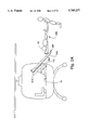
- FIG. 1 is a perspective view of the device embodying the present invention.
- FIG. 2A is a front view of the device of FIG. 1 with the litter and patient thereon being loaded onto the device and into a helicopter.
- FIG. 2B is a front view of the device of FIG. 1 with a patient thereon loaded into a helicopter.
- FIG. 2C is a front view of the device of FIG. 1 with a patient thereon loaded and rotated in a helicopter.
- FIG. 3A is a perspective view of the base assembly of the device illustrated in FIG. 1.
- FIG. 3B is a perspective view of the base assembly of the device illustrated in FIG. 1 showing rotation of plate relative to the base support plate.
- FIG. 4 is a cross-sectional view of the base assembly illustrated in FIG. 3A, taken along line 4--4.
- FIG. 5 is a cross-sectional view of the turntable locking subassembly of the base assembly illustrated in FIG. 3A, taken along line 5--5.
- FIGS. 6A and 6B are cross-sectional views of the base assembly illustrated in FIG. 3A, taken along line 6--6, showing the turntable locking subassembly in unlocked and locked positions, respectively.
- FIG. 7 is a cross-sectional view of the base assembly illustrated in FIG. 3A, taken along line 7--7, mounted on a track via a roller bearing.
- FIG. 8A is a top view of the device illustrated in FIGS. 2 and 3A loaded into a helicopter.
- FIG. 8B is a top view of two devices illustrated in FIGS. 2 and 3A loaded into a helicopter.
- FIGS. 9A and 9B are cross-sectional views of the base assembly illustrated in FIG. 3A, taken along line 9--9, showing the base slide locking subassembly in unlocked and locked positions, respectively.
- FIG. 10 is a perspective, cut-away view of the device illustrated in FIG. 1 showing the interconnecting assembly without the telescoping members.
- FIGS. 11A, 11B and 11C are side views of the device illustrated in FIG. 1 showing the selected tilt positions of the platform assembly.
- FIG. 12 is a rear view of the various components of the interconnecting assembly illustrated in FIG. 10, with the telescoping members in position and showing only the rear yoke and struts.
- FIG. 13 is a perspective view of the interconnecting assembly showing the struts being actuated by the actuating means.
- FIG. 14 is a perspective view of the actuating plates and pulleys of the interconnecting assembly.
- FIG. 15 is a perspective, cut-away view of the device illustrated in FIG. 1 showing the litter slide means of the platform assembly.
- FIG. 16 is a cross-sectional view of the device illustrated in FIG. 15, taken along line 16--16, showing the litter slide means, with the litter platform thereon.
- FIG. 17 is a perspective, cut-away view of the litter slide locking subassembly.
- FIGS. 18A and 18B are rear, cross-sectional views of the litter slide locking subassembly illustrated in FIG. 17, taken along line 18--18.
- FIG. 19 is a cross-sectional view of the litter slide locking subassembly illlustrated in FIG. 17, taken along line 19--19.
- FIGS. 20A and 20B are cross-sectional views of the litter engaging means illustrated in FIG. 17, taken along line 20--20.
- FIGS. 1-20 illustrate a patient loading system and transport device embodying the features of the present invention.
- the device 10 generally comprises a base assembly 100, an interconnecting assembly 300 and a platform assembly 500 upon which a patient 20 may be positioned.
- the base assembly 100 is connectable to the floor 14 of a helicopter.
- the interconnecting assembly 300 extends between and interconnects the base assembly 100 and the platform assembly 500.
- the device 10 may be capable of four independent ranges of motion.
- the base assembly 100 primarily functions to support the platform assembly 500 and patient 20 thereon via the interconnecting assembly 300. Furthermore, and as illustrated in FIGS. 1, 3A-3B, 4-9, the base assembly 100 accommodates two independent ranges of motion. In the illustrated embodiment, in which the first range of motion is provided for purposes of facilitating the loading and unloading of the patient 20, the base assembly 100 allows rotational (e.g., turntable) movement of the patient 20 relative to the helicopter while supporting the interconnecting and platform assemblies 300, 500, as well as the patient 20.
- the base assembly 100 includes a circular plate 106 which is rotatably captured within a base support plate 112, which is connected to the floor 14 of the helicopter.
- the base assembly 100 may also include a turntable locking subassembly 150, which locks the circular plate 106 in any one of a plurality of selected rotational positions relative to the base support plate 112.
- the base assembly 100 accommodates a second range of motion.
- the base assembly 100 may include a plurality of roller bearings 120 attached to the underside of the base support plate 112 and slidably engageable with least one seat track 124 to allow slidable movement of the base assembly 100, interconnecting assembly 300, platform assembly 500 and patient 20 thereon in a direction transverse to a longitudinal axis 16 of the helicopter and relative to the floor 14.
- a device 10 and patient 20 thereon can be easily moved to facilitate medical treatment of the patient and/or to accommodate loading, transport and/or medical treatment of at least a second patient aboard the helicopter 20.
- the interconnecting assembly 300 shown in FIGS. 1, 10-13 primarily functions to support the platform assembly 500 and to translate forces/loads applied on the platform assembly 500 to the base assembly 100. Furthermore, the interconnecting assembly 300 accommodates a third range of motion of the device 10. For purposes of allowing tilting (e.g., pitching) of the patient 20 and platform assembly 500 relative to the base assembly 100 to facilitate medical treatment and loading and unloading of the patient, the interconnecting assembly 300 may include at least one lower bracket 306 interconnected to the base assembly 100, at least one upper bracket 312 interconnected to the platform assembly 500 and a hinging means 318 for hingedly interconnecting the lower and upper brackets 306, 312 for pivotal movement therebetween.
- the platform assembly 500 may be articulated into an anti-shock (Trendelenburg) position and into a reverse anti-shock (Reverse Trendelenburg) position, as will be described in more detail below.
- the interconnecting means 300 may also include a supporting means 350 for supporting patient loads and for reacting to crash loads.
- the supporting means 350 functions to transfer loads from the platform assembly 500 to the base assembly 100 since the supporting means 350 extends from and interconnects the platform assembly 500 and the base assembly 100.
- the supporting means 350 may comprise a plurality of telescoping members, such as center pin actuated struts 356.
- the interconnecting assembly 300 may also include an actuating means 400 for controlling the lengths of the struts 356 such that the platform assembly 500 is positionable at any one of a plurality of desired tilt angles.
- the platform assembly 500 illustrated in FIGS. 1, 2A-2C, and 14-18 primarily functions to receive and support the stretcher or litter 506 upon which the patient 20 is positioned. Moreover, the platform assembly 500 accommodates a fourth range of motion of the device 10.
- the platform assembly 500 comprises an upper plate 512 interconnected with the interconnecting assembly 300, a plurality of linear bearings 518 mounted to the upper plate 512, at least one rail or cylindrical rod 524 and a litter platform 530 for receiving the litter 506.
- the platform assembly 500 also includes a litter platform locking subassembly 550 which functions to selectively position the litter platform 530 relative to the upper plate 512, interconnecting assembly 300 and base assembly 100.
- the platform assembly 500 includes a litter engaging subassembly 580 which functions to retain or capture the litter 506 within the litter platform 530.
- the base assembly 100 comprises a circular plate 106 which is rotatably captured or retained between a closure plate 116 secured to the underside of the base support plate 112 and an inwardly projecting annular lip 114 on the circular interior opening of the base support plate 112.
- the circular plate 106 may include an annular tab 108.
- the circular plate 106 is retained within the base support plate 112 due to the support of the closure plate 116 and the overlapping interface of the annular lip 114 and the annular tab 108.
- Rotation of the circular plate 106 relative to the base support plate 112 may be enhanced by positioning an annular bearing 118 having low friction characteristics between at least the lower surface of the annular tab 108 and the closure plate 116.
- the annular bearing 118 comprises Teflon (TFE).
- a second Teflon bearing 120 may be positioned between the lower surface of the annular lip 114 and the upper surface of the annular tab 108 to further enhance rotation of the circular plate 106 relative to the base support plate 112.
- the Teflon bearings may have a rectangular, circular, elliptical or square cross-section.
- the closure plate 116 may be secured to the underside of the base support plate 112 by securing members selected from the group consisting of screws, pins, bolts, rivets and the like.
- the rotational position of the circular plate 106 relative to the base support plate 112 may be selectively locked and released by a turntable locking subassembly 150.
- the turntable locking subassembly 150 is interconnected to the base support plate 112 and comprises a handle 154 operatively connected to a retractable spring plunger 162 which actuates at least one pin 158 upon rotation of the handle 154.
- the pins 158 of the retractable spring plunger 162 are receivable within correspondingly sized holes 110 in the circular plate 106.
- the hand retractable spring plunger 162 is manufactured by the Reid Tool Supply Co. and is available under Part No. PRSN-500S.
- the operator may grasp and move the handle 154 downwardly, in an arcuate motion, in order to actuate the pins 158 downwardly such that the pins 158 enter the corresponding holes 110 in the upper surface of the circular plate 106.
- the holes 110 are positioned in the upper surface of the circular plate 106 such that rotation of the circular plate 106 relative to the base support plate 112 may be fixed or locked at 15° intervals when the handle 154 is rotated towards the base support plate 112.
- the operator may grasp and move the handle 154 upwardly, in an arcuate motion, in order to move the pins 158 upwardly, out of the holes 110 of the circular plate 106.
- This allows the circular plate 106 and platform assembly 500 to be freely rotatable relative to the base support plate 112.
- the holes 110 may be positioned on the side surface of the circular plate 106 and the turntable locking subassembly 150 oriented accordingly (not shown).
- the second range of motion of the device 10 involves translational motion along an axis transverse to the longitudinal axis 16 of the helicopter.
- the base assembly 100 may be slidably mounted upon at least one track 124 (e.g., seat track) via a plurality of roller bearings 120.
- track 124 e.g., seat track
- two seat tracks 124 may be secured to the floor 14 of the helicopter such that the seat tracks 124 are parallel to each other and are oriented perpendicular to the longitudinal axis 16 of the helicopter.
- Two pairs of roller bearings 120 secured within brackets 122 may be mounted to the underside of the base support plate 112, proximate the corners of the base support plate 112 such that the two pairs of roller bearings 120 correspond to the distance between the two seat tracks 124.
- FIG. 7 shows the seat tracks 124 having an I-beam cross-section.
- the roller bearings 120 positioned within the brackets 122 may roll along the top surface of the seat tracks 124 until the desired transverse position is reached.
- the side structures 126 of the brackets 122 assist in maintaining rolling engagement between the roller bearings 120 and the upper surface of the seat track 124.
- the seat tracks may comprise c-shaped members.
- the brackets 122 may also assist in maintaining the position of the base support plate 112 relative to the seat tracks 124 once the desired transverse position is reached.
- the base assembly 100 may also include a seat track locking means.
- the base assembly 100 includes a seat track locking means comprising a plurality of thumb screws 130 threadedly receivable within a plurality of holes 132 in the base support plate 112 and a plurality of detents 136 in the seat track 124 which are capable of receiving an end portion of the thumb screws 130.
- an operator lock the base assembly 100 in position by threading the thumb screws 130 downwardly such that the end portion of at least one of the thumb screws 130 enters a corresponding detent 136. Furthermore, as the thumb screws 130 are threaded downwardly to lock the base assembly 100 in position, a plurality of tabs 128 extending inwardly from the side structures 126 of the roller bearing brackets 122 may frictionally engage the seat tracks 124.
- the base support plate 112 and roller bearing brackets 122 attached thereto may be forced upwardly, away from the upper surface of the seat track 124, causing the upper surface of the tabs 128 of the roller bearing brackets 122 to frictionally engage the seat track 124.
- the base support plate 112 may be released at the desired time by unscrewing the thumb screws 130 to allow rolling engagement and movement of the roller bearings 120 relative to and on the seat tracks 124.
- the interconnecting assembly 300 illustrated in FIGS. 1 and 10-13, provides for the third range of motion, substantially as described above.
- tilting e.g., pitching
- the interconnecting assembly 300 This is especially useful in treating a patient as the platform assembly 500 and patient 20 thereon can be tilted or articulated into an anti-shock position and into a reverse anti-shock position, as noted above.
- the tilt action accommodates the medical needs of the patient 20 as it allows access to the patient's head facilitating all advanced airway procedures.
- tilting the platform assembly 500 such that the patient's head is elevated above the patient's feet may enhance medical treatment of some head wounds.
- the interconnecting assembly 300 comprises two lower brackets 306, two upper brackets 312 and a hinging means 318 interconnecting the upper and lower brackets 306, 312.
- the lower brackets 306 are securable to the circular plate 106, which includes a number of holes (e.g., through holes or threaded holes) (not shown) in the upper surface of the circular plate 106.
- securing members e.g., rivets, pins, screws, etc. may be used to attach the the lower brackets 306 to the circular plate 106.
- the upper brackets 312 are attachable to the underside of the upper plate 512 of the platform assembly 500 via securing members (e.g., rivets, pins, screws, etc.) which are received within holes (e.g., through holes or threaded holes) (not shown) of the upper brackets 312 and the upper plate 512.
- securing members e.g., rivets, pins, screws, etc.
- the supporting means 350 also interconnects and extends between the platform assembly 500 and the base assembly 100.
- the lower and upper brackets 306, 312 are hingedly or pivotally interconnected by hinging means 318.
- the hinge means 318 is interposed between the upper plate 512 and the circular plate 106 such that the hinge means 318 is elevated relative to the circular plate 106.
- the hinging means 318 accommodates tilting or pitching of the platform assembly 500 relative to the base assembly 100.
- the hinging means 318 includes bushings 324 and rods 328 which are receivable within adjacently positioned bores 308, 316 of the lower and upper brackets 306, 312, respectively.
- the lower and upper brackets 306, 312 are positioned such that an upper side portion of each of the lower brackets 306 is proximate a lower side portion of each of the upper brackets 312.
- the interconnecting assembly 300 may include supporting means 350 for use in supporting and counterbalancing the patient load, especially during tilting operations.
- the supporting means 350 acts to counterbalance loads applied during tilting operations to thereby inhibit uncontrolled tilting of the platform assembly 500 and patient 20.
- the length of the supporting means 350 may be selected to dictate the desired degree of tilting of the platform assembly 500 relative to the base assembly 100.
- the supporting means 350 provides significant safety advantages as the supporting means 350 reacts to crash loads. In this regard, as crash loads in an aircraft can reach 6-20 times the force of gravity (g), the supporting means 350 may be designed to counteract and/or withstand such impact forces. It can thus be appreciated that the supporting means 350 are designed to translate forces and loads applied by and/or on the platform assembly 500 to the base assembly 100.
- the supporting means 350 may comprise at least two telescoping members. Such telescoping members should counterbalance the patient load in an unlocked condition to avoid uncontrolled tilting, react to crash loads and patient loads in a locked condition (e.g., resist both tensile and compressive forces), and have sufficient throw (e.g., telescoping capability) to allow tilting of the platform assembly 500 to accommodate loading and unloading of the patient and to facilitate medical treatment of the patient.
- the degree of tilting attainable is governed not only by the length and throw of the telescoping members, but also by the distance between the platform assembly 500 and the floor 14 of the helicopter, which is determined by the heights of the lower and upper brackets 306, 312.
- the telescoping members and height of the lower and upper brackets 306, 312 are selected such that the platform assembly 500 is controllable and tiltable in either direction at least between about 1° and about 60°, and more preferably, at least between about 5° and about 45°, and even more preferably, at least between about 10° and about 20°. In the illustrated embodiment, the platform assembly is tiltable in either direction between about 12° and about 15°. At least one telescoping member should be positioned on either side of the hinging means 318.
- the orientation of the telescoping members relative to the upper plate 512 and the circular plate 106, as well as the distance between the telescoping members, is dependent upon the length and throw of the telescoping members and the distance between the upper plate 512 and the circular plate 106.
- the interior space available (e.g., cargo space) in the aircraft may also influence the degree of tilt, as well as the length of the telescoping members. Accordingly, the degree of controlled tilting possible is dependent upon these factors.
- the telescoping members comprise two pairs of struts 356 which extend between and interconnect the platform assembly 500 and base assembly 100.
- Each pair of struts 356 is positioned and oriented on each side of the hinging means 318 such that the platform assembly 500 is supported and controllable, especially during tilting operations.
- the struts 356 are Bloc-O-Lift gas springs, which are oil- or gas-filled struts. These struts 356 are center pin actuated and manufactured by Stabilus, Part No. 292121000257/95.
- Such struts 356 are positioned and oriented relative to the upper plate 512 and the circular plate 106 to allow tilting of the platform assembly 500 of at least between about 12° and about 15° in either direction.
- such struts 356 have a spring force of about 1000 Newtons (224 lbs), a locking force in compression of about 4000 Newtons (899 lbs) and a locking force in tension of about 4500 Newtons (1012 lbs).
- the stroke length of the struts 356 of the present invention is about 60 millimeters (2.36 inches) and has a total length (extended) of about 265 millimeters (10.43 inches).
- the supporting means 350 may comprise two struts (not shown), wherein a single strut may be positioned on each side of the hinging means 318, substantially as described above.
- the supporting means 350 is controllable by the actuating means 400.
- an operator may grip or grasp the actuating means 400 about the platform assembly 500 to release and lock the supporting means 350 while tilting the platform assembly 500.
- the actuating means 400 controls the throw of the telescoping members.
- the actuating means 400 may be activated by an operator gripping the handle of the actuating means 400, which is positioned about the platform assembly, to unlock the telescoping members from their present condition and throw, thus allowing the throw of the telescoping members to be varied until the desired tilt angle is achieved as the operator applies tilting forces to the platform assembly.
- the throw of the struts 356 is varied by applying a force, via at least one of the handles 430, 432, on each of the center pins 362, which extend from the throw extensions 368 of the struts 356.
- the actuating means 400 applies a generally upwardly oriented force against the center pins 362 to unlock the struts 356.
- the throw or length of the struts 356 may be varied to facilitate counterbalanced tilting of the litter platform 530 since the struts 356 react to both compressive and tensile loading.
- the actuating means 400 applies an upwardly oriented force on the center pins 362 since the struts 356 are oriented such that the center pins 362 extend downwardly.
- such an orientation of the struts 356 is desirable as blood, dirt, debris and other contaminants are less likely to contact the center pins 362 and throw extension 368.
- a shroud may surround the interconnecting assembly 300 to keep the interconnecting assembly 300 clean.
- the actuating means 400 comprises a system of pulleys and cables interconnected with the actuating plates 420, each of which are positioned proximate the center pins 362 of the struts 356.
- the actuating means 400 may be activated by at least one handle 430 positioned proximate the sides or ends of the litter platform 530. Once activated, the articulating plates 420 are moved into contact with the center pins 362 to actuate the center pins 362. In this unlocked condition, the degree of tilt of the platform assembly 500 may be varied until the desired degree of tilt is achieved.
- the actuating means 400 is deactivated by the handle 430, which causes the articulating plates 420 to move downwardly, away from the center pins 362, to thereby lock the struts 356 in a specific throw position corresponding to the degree of tilt desired.
- the actuating means comprises a handle 430 connected to a shaft 416 via a first cable 404 and pulleys 406, 408 and a lug 410 which is attached to the outer surface of the shaft 416.
- the shaft 416 may also be rotated via a second handle 432 connected directly thereto.
- the shaft 416 is rotatably attached to the underside of the litter platform 530 by brackets 418 and connected to the upper plate 512 via a shaft guide 412, the shaft 416 being rotatable and slidable with respect to the shaft guide 412 and the upper plate 512.
- the shaft 416 Interfacing with the shaft 416 via a lug 411 on the shaft 416 and a second cable 422 attached thereto is an upper plate pulley 448, which is secured to the underside of the upper plate 512.
- the second cable 422 has a spherical member 424 at an end thereof for engagement with a spool pulley 414, which is operatively connected to a dual pulley 426 via a third cable 440.
- the dual pulley 426 is rotatably mounted to the spool yoke 428 which is interconnected to the lower brackets 306 of the interconnecting assembly 300.
- the dual pulley 426 is rotatable about the spool yoke 428, the dual pulley 426 does not move upwardly or downwardly with the spool pulley 414, which moves upwardly or downwardly relative to the upper plate 512 upon movement of one of the handles 430, 432 (as will be described hereinbelow).
- the dual pulley 426 includes two pulleys 436, 438 which operatively connects the spool pulley 414 (and therefore the handles 430, 432) to the actuating plates 420 via the third cable 440, which is wound about the dual pulley 426, a central dual pulley 442, the yoke pulleys 444, 446 and through and/or about the pins 421.
- Two actuating plates 420 are pivotally engageable on each of the yokes 380 at an end of each of the actuating plates 420 and hingedly interconnected to a corresponding actuating plate 420 via a pin 421, which is operatively connected to the cable 440.
- rotation of at least one of the handles 430, 432 results in upward translation of the spool pulley 414, relative to the upper plate 512 and the dual pulley 426, which, in turn, raises the central dual pulley 446, which, in turn, pulls the pins 421 upwardly, which causes the actuating plates 420 to move toward the center pins 362 of the struts 356.
- Such action releases the struts 356 from a locked condition, which enables the platform assembly 500 to supportably tilt to a selected tilted position.
- Rotation of the handle(s) 430, 432 in the opposite rotational direction results in downward translation of the spool pulley 414, relative to the upper plate 512 and the dual pulley 426, which, in turn, causes the actuating plates 420 to move away from the center pins 362 of the struts 356.
- Such action locks the struts 356 at selected lengths for purposes of supporting the platform assembly 500, for example, in a desired tilted position.
- the center pins 362 are mounted to the yokes 380 at an elevated a distance above the circular plate 106. This provides space in which the actuating plates 420 may move against and away from the center pins 362 of the struts 356.
- the collars 172 of the throw extension portions 368 of the struts 356 are secured to yokes 380. This allows for extension of the struts 356 relative to the yokes 380.
- the yokes 380 are generally c-shaped members which are pivotally interconnected to the circular plate 106 via c-shaped brackets 382 and pins therebetween to facilitate tilting of the platform assembly 500 as the throw of the struts 356 is varied.
- the yokes 380 are hingedly connected to the yoke brackets 382 by a pin and bushing arrangement through the bores in the yokes 380 and brackets 382.
- the ends opposite the center pins 362 of the struts 356 may be pivotally secured to the upper plate 512 by brackets 516, shown in FIGS. 11A-11B.
- the fourth degree of motion is provided by the platform assembly 500.
- the platform assembly 500 comprises an upper plate 512 connected to the interconnecting assembly 300, a litter platform 530 slidably secured to the upper plate 512 via a litter slide means, and a litter 506 which supports the patient 20.
- the litter slide means provides the fourth degree of motion as it allows the litter platform 530 to slide relative to the upper plate 512 and base assembly 100 interconnected thereto.
- the litter slide means combined with the tilting features of the device 10, may facilitate loading of the patient onto the helicopter as the litter 506 and the patient 20 thereon can engage the litter platform 530 substantially below the floor 14 of the helicopter.
- the litter slide means comprises a plurality of linear bearings 518 having roller bearings therein and at least one rod 524 slidably captured therein.
- the litter slide means includes four linear bearings 518 which are mounted on the top side of the upper plate 512 in positions corresponding to the position and orientation of the rods 524.
- the rods 524 may be oriented along a longitudinal axis of the litter platform 530 and may be attached to the underside of the litter platform 530.
- the linear bearings 518 are sized to slidably capture the rods 524 to allow slidable engagement between the litter platform 530 and the upper plate 512.
- Stops may be provided on the upper plate 512 or, alternatively, on the litter platform 530 to limit the length of sliding of the litter platform 530 relative to the upper plate 512.
- the litter platform 530 may slide about 20 inches in either direction relative to a center point on the upper plate 512.
- the rods 524 may be attached to the top side of the upper plate 512 and the linear bearings 518 secured to the underside of the litter platform 530 (not shown).
- the platform assembly 500 may include a litter platform locking subassembly 550, shown in FIGS. 17-19.
- the litter platform locking subassembly 550 may comprise an upper plate bar 556 attached to the upper plate 512, a plurality of retractable spring plungers 562 having pins 566 extendable therefrom, a torque bar or tube 570 for engaging the plungers 562 to thereby extend and retract the pins 566.
- a plurality of lugs 571 may be positioned on the surface of the torque tube 570.
- the plungers 562 may be attached to the underside of the litter platform 530 via brackets 568 and positioned proximate the upper plate bar 556 such that the pins 566 of the plungers 562 are extendable into any of a number of bores 558 in the upper plate bar 556.
- the torque tube 570 is attachable to the underside of the litter platform 530 via brackets 578.
- each of the handles 574, 576 for rotating the torque tube 570 are operatively interconnected to the torque tube 570 via a rod 577 and a link 573, the rod 577 being slidable within the support brackets 579 which are attached to the underside of the litter platform 530.
- the link 573 extends between a lug 571 on the torque tube 570 and a sleeve 575 which is fixedly attached to the rod 577.
- the rod 577 slides within the brackets 579, causing the torque tube 570 to rotate.
- rotation of the torque tube 570 causes the pins 566 of the plungers 562 to extend or retract, to lock or release the litter platform 530 relative to the upper plate 512.
- the handles 574, 576 may engage the torque tube 570 via a system of pulleys and cables (not shown).
- the telescoping members may be actuated for tilting purposes as the litter platform 530 is translated linearly (e.g., slid) relative to the upper plate 512 since the actuating means 400 and litter platform locking subassembly 550 are independently operable by the operator.
- the handles 430, 432 of the actuating means 400 and the handles 474, 476 of the litter platform locking subassembly 550 may be operated by a single operator.
- a handle for each of the actuating means 400 and litter platform locking subassembly 550 may be located proximate each other such that the right hand of the operator may control tilting operations via the actuating means 400 while the operator's left hand controls sliding operations via the litter platform locking subassembly 550.
- the handles of actuating means 400 and the litter platform locking subassembly 550 may be controlled by the left and right hands, respectively, of the operator.
- placement of these handles 430, 432, 474, 476 proximate the side and/or end of the litter platform 530 facilitates tilting or sliding operations as the operator is able to grasp about the litter platform 530 while engaging one or more of the handles.
- the platform assembly 500 may include a litter engaging subassembly 580, shown in FIGS. 16 and 18A and 18B.
- a litter engaging subassembly 580 is positioned on each end of the litter platform 530 to secure a litter 506 therebetween by engaging end portions 508 of the litter 506.
- the litter engaging subassembly 580 may comprise a retractable spring plunger 584 and c-shaped member 586 which corresponds in configuration to the end portions 508 of litter 506.
- the handle 594 may be used to rotate the c-shaped member 586 in and out of position to secure and release an end portion 508.
- the handle 594 operatively engages the plunger 584 in order to actuate the pin 592 of the plunger 584 into (or out of, depending upon the rotation of the handle 594) the bore 596, which is positioned in the litter platform 530.
- the end portions 508 of the litter 506 may include litter projections 510 and the c-shaped member 586 may include a corresponding number of bores 588 for receiving the litter projections 510.
- the components of the base assembly 100, interconnecting assembly 300 and platform assembly 500 should exhibit superior strength and bending characteristics based upon the forces applied to the components, including crash loads. Moreover, in the interests of improving fuel economy and in view of the load carrying constraints for aircraft, the components for the device 10 should be lightweight.
- major load bearing components of the device 10, including the circular plate 106, base plate support 112, closure plate 116, seat tracks 124, lower and upper brackets 306, 312, yokes 380, actuating plate 420, litter platform 530, litter 506, upper plate 512, upper plate bar 556, cylindrical rods 524 and c-members 594 may be fabricated from aluminum or steel alloys.
- this embodiment of the present invention is particularly apt for use in an aircraft, and specifically a helicopter, it should be appreciated that the present invention is also applicable to other vehicles, especially where it is desirable to transport and treat a patient in route to a medical facility.
Abstract
Description
Claims (22)
Priority Applications (4)
| Application Number | Priority Date | Filing Date | Title |
|---|---|---|---|
| US08/542,598 US5785277A (en) | 1995-10-13 | 1995-10-13 | Patient loading system and transport device for aircraft |
| US08/643,399 US5738306A (en) | 1995-10-13 | 1996-05-06 | Articulating patient loading system and transport device for aircraft |
| PCT/US1996/016432 WO1997013684A1 (en) | 1995-10-13 | 1996-10-11 | Aircraft articulating patient loading and transport system |
| AU74301/96A AU7430196A (en) | 1995-10-13 | 1996-10-11 | Aircraft articulating patient loading and transport system |
Applications Claiming Priority (1)
| Application Number | Priority Date | Filing Date | Title |
|---|---|---|---|
| US08/542,598 US5785277A (en) | 1995-10-13 | 1995-10-13 | Patient loading system and transport device for aircraft |
Related Child Applications (1)
| Application Number | Title | Priority Date | Filing Date |
|---|---|---|---|
| US08/643,399 Continuation-In-Part US5738306A (en) | 1995-10-13 | 1996-05-06 | Articulating patient loading system and transport device for aircraft |
Publications (1)
| Publication Number | Publication Date |
|---|---|
| US5785277A true US5785277A (en) | 1998-07-28 |
Family
ID=24164506
Family Applications (1)
| Application Number | Title | Priority Date | Filing Date |
|---|---|---|---|
| US08/542,598 Expired - Lifetime US5785277A (en) | 1995-10-13 | 1995-10-13 | Patient loading system and transport device for aircraft |
Country Status (1)
| Country | Link |
|---|---|
| US (1) | US5785277A (en) |
Cited By (33)
| Publication number | Priority date | Publication date | Assignee | Title |
|---|---|---|---|---|
| GB2340082A (en) * | 1998-07-31 | 2000-02-16 | Advanced Transport Technology | Stretcher platform |
| US6332638B1 (en) * | 1999-03-05 | 2001-12-25 | Stem S.R.L. | Apparatus for loading stretchers onto ambulances |
| US6527263B1 (en) | 2002-02-04 | 2003-03-04 | Nick Verbrugge | Shock absorbing transport frame |
| FR2830437A1 (en) * | 2001-10-04 | 2003-04-11 | Rts Chapuis | System for anchoring wheeled stretcher to ambulance floor comprises two side catches which engage with stretcher axle, central lock in different position being fastened to frame at head of stretcher |
| US6585188B2 (en) * | 2001-04-04 | 2003-07-01 | Agusta S.P.A. | Rescue vehicle |
| US20050100919A1 (en) * | 1999-05-14 | 2005-05-12 | Brandeis University, A Massachusetts Corporation | Nucleic acid-based detection |
| US20060045647A1 (en) * | 2004-08-30 | 2006-03-02 | Nick Verbrugge | Shock absorbing transport frame |
| US20070278350A1 (en) * | 2006-05-18 | 2007-12-06 | Airbus Uk Limited | Aircraft walkway |
| US20080023976A1 (en) * | 2006-07-28 | 2008-01-31 | Myers Will J | Patient support system for medical transport vehicles |
| US20080217477A1 (en) * | 2007-01-31 | 2008-09-11 | Airbus Deutschland Gmbh | Aircraft with seat arrangement having different seat configurations for transport of a patient |
| US20090014585A1 (en) * | 2003-04-22 | 2009-01-15 | Hans Gygax | Light Plane in the Ultralight Category and Sport Plane Category |
| US20090255058A1 (en) * | 2008-04-15 | 2009-10-15 | Ferno-Washington, Inc. | Apparatus and methods for litter support system for vehicles |
| US20100051746A1 (en) * | 2006-09-12 | 2010-03-04 | Law Sondra F | System and method for integrating handicapped accessible seats into aircraft interior configurations |
| US8336939B2 (en) | 2010-10-04 | 2012-12-25 | Air Methods Corporation | Roll-on, foldable litter and patient handling system for emergency transport vehicles |
| US20140007343A1 (en) * | 2012-07-03 | 2014-01-09 | Woodlark Circle, Inc. | Method of transferring a patient to a jet |
| US8636154B2 (en) | 2010-07-12 | 2014-01-28 | Ferno-Washington, Inc. | Litter support systems for medical care units and methods of their use |
| US8992238B2 (en) | 2010-07-12 | 2015-03-31 | Ferno-Washington, Inc. | Mounting system having a mounting plate with mounting studs and electrical contacts |
| US20150209203A1 (en) * | 2012-03-15 | 2015-07-30 | The Boeing Company | Method of transporting a patient |
| US9362610B2 (en) | 2012-02-14 | 2016-06-07 | Ferno-Washington, Inc. | Quick antenna attachment system |
| US9364376B2 (en) | 2011-03-16 | 2016-06-14 | Raymond L. Crawford | System and method for transferring a wheeled load into a transport vehicle |
| US9611975B2 (en) | 2013-02-11 | 2017-04-04 | Ferno-Washington, Inc. | Equipment mounting system |
| US9944217B2 (en) | 2013-02-11 | 2018-04-17 | Ferno-Washington, Inc. | Equipment mounting system |
| WO2018161107A1 (en) * | 2017-03-08 | 2018-09-13 | Helimods Pty Ltd | Stretcher loading assembly |
| US10307313B2 (en) | 2013-02-11 | 2019-06-04 | Ferno-Washington, Inc. | Equipment mounting system |
| US10398203B2 (en) | 2014-02-11 | 2019-09-03 | Ferno-Washington, Inc. | Crash-ready, portable, compartmentalization device |
| US10398207B2 (en) | 2014-02-11 | 2019-09-03 | Ferno-Washington, Inc. | Crash-ready, portable, compartmentalization device |
| US10786055B2 (en) | 2014-07-18 | 2020-09-29 | Ferno-Washington, Inc. | Crash-ready, portable, compartmentalization device |
| AU2020102223B4 (en) * | 2019-09-13 | 2021-06-17 | Five Rings Aerospace Pty Ltd | Stretcher loader system |
| US11083265B2 (en) | 2014-02-11 | 2021-08-10 | Ferno-Washington, Inc. | Magnetic pouch attachment mechanism with crash stable locking teeth |
| WO2022011353A1 (en) * | 2020-07-10 | 2022-01-13 | Air Methods Corporation | Litter platform support and positioning system |
| US11376172B2 (en) * | 2020-08-21 | 2022-07-05 | Dan Bacon, IV | Patient transporting device using a docking member for an emergency medical vehicle |
| US11673668B2 (en) * | 2019-09-20 | 2023-06-13 | Goodrich Corporation | Powered rail mounted air cargo cart |
| CN116492155A (en) * | 2023-04-26 | 2023-07-28 | 上海新纪元机器人有限公司 | Active and passive hybrid damping stretcher and control method thereof |
Citations (27)
| Publication number | Priority date | Publication date | Assignee | Title |
|---|---|---|---|---|
| GB190001715A (en) * | 1900-01-26 | 1900-12-15 | Horace Manders | Improved Hospital Car for Field use and the like. |
| US771039A (en) * | 1903-09-16 | 1904-09-27 | Fredrick William Boecker | Bed or couch. |
| US943827A (en) * | 1907-09-11 | 1909-12-21 | Champion Chemical Company | Post-mortem table. |
| US2201890A (en) * | 1939-01-27 | 1940-05-21 | Dunn John Stephen | Collapsible stretcher |
| US2512160A (en) * | 1946-07-03 | 1950-06-20 | E & F Koenigkramer Co | Carriage having universal horizontal shifting platform |
| GB754052A (en) * | 1954-07-24 | 1956-08-01 | Dunlop Rubber Co | Improvements relating to stretchers |
| US3151343A (en) * | 1963-11-01 | 1964-10-06 | Union Bag Camp Paper Corp | Combination splint and litter |
| DE1491267A1 (en) * | 1965-07-20 | 1969-10-02 | Christian Miesen Fa | Facility for ambulance vehicles |
| US3566422A (en) * | 1969-01-23 | 1971-03-02 | Allen P Klippel | Spine board apparatus for rescue of fracture patients and the like |
| US3605136A (en) * | 1969-10-27 | 1971-09-20 | Us Army | Powered litter rack |
| US3648305A (en) * | 1969-12-09 | 1972-03-14 | Robert A Ersek | Patient carrier |
| US3840265A (en) * | 1971-09-13 | 1974-10-08 | Inst For Ind Res & Standards | Construction of stabilised platform |
| US3886606A (en) * | 1973-05-29 | 1975-06-03 | John Guythar Bradford | Foldable casualty carrier |
| US3947686A (en) * | 1974-04-25 | 1976-03-30 | The Babcock & Wilcox Co. | Graphite composite X-ray transparent patient support |
| US4115884A (en) * | 1977-09-28 | 1978-09-26 | Air Medic, Inc. | Stretcher supporting structure for airplanes, or the like |
| US4178032A (en) * | 1978-05-01 | 1979-12-11 | United Technologies Corporation | Apparatus for synchronously elevating and lowering air-ambulance litter with crash attenuation capability |
| US4252594A (en) * | 1977-08-31 | 1981-02-24 | The Babcock & Wilcox Company | X-ray patient support stretcher and method for fabrication |
| US4378128A (en) * | 1980-01-10 | 1983-03-29 | Christian Miesen, Fahrzeug Und Karosseriewerk Gmbh | Ambulance |
| US4566445A (en) * | 1983-07-29 | 1986-01-28 | Jelsma Richard K | Stretcher for persons with spinal injuries |
| US4783025A (en) * | 1987-05-05 | 1988-11-08 | Atlantic Aviation Corporation | Emergency medial service-interior for aircraft |
| US4957121A (en) * | 1988-07-05 | 1990-09-18 | Arizona Technology Development Corporation | Mobile intensive care patient handling system apparatus and method of using |
| US5054049A (en) * | 1989-03-22 | 1991-10-01 | Kabushiki Kaisha Toshiba | Patient support means for x-ray absorption compensation in computer tomography system |
| US5274864A (en) * | 1992-10-08 | 1994-01-04 | Air Methods | Knock down litter board |
| US5372339A (en) * | 1992-10-07 | 1994-12-13 | Air Methods Corporation International | Multi-tiered litter rack system |
| US5435027A (en) * | 1993-08-09 | 1995-07-25 | Ferno-Washington, Inc. | Roll-in cot with high ground clearance |
| US5490703A (en) * | 1993-06-04 | 1996-02-13 | Vancouver Island Helicopters Ltd. | Patient transport system |
| US5595470A (en) * | 1994-03-07 | 1997-01-21 | American Airlines, Incorporated | Lift for physically-challenged passengers and method of operation |
-
1995
- 1995-10-13 US US08/542,598 patent/US5785277A/en not_active Expired - Lifetime
Patent Citations (27)
| Publication number | Priority date | Publication date | Assignee | Title |
|---|---|---|---|---|
| GB190001715A (en) * | 1900-01-26 | 1900-12-15 | Horace Manders | Improved Hospital Car for Field use and the like. |
| US771039A (en) * | 1903-09-16 | 1904-09-27 | Fredrick William Boecker | Bed or couch. |
| US943827A (en) * | 1907-09-11 | 1909-12-21 | Champion Chemical Company | Post-mortem table. |
| US2201890A (en) * | 1939-01-27 | 1940-05-21 | Dunn John Stephen | Collapsible stretcher |
| US2512160A (en) * | 1946-07-03 | 1950-06-20 | E & F Koenigkramer Co | Carriage having universal horizontal shifting platform |
| GB754052A (en) * | 1954-07-24 | 1956-08-01 | Dunlop Rubber Co | Improvements relating to stretchers |
| US3151343A (en) * | 1963-11-01 | 1964-10-06 | Union Bag Camp Paper Corp | Combination splint and litter |
| DE1491267A1 (en) * | 1965-07-20 | 1969-10-02 | Christian Miesen Fa | Facility for ambulance vehicles |
| US3566422A (en) * | 1969-01-23 | 1971-03-02 | Allen P Klippel | Spine board apparatus for rescue of fracture patients and the like |
| US3605136A (en) * | 1969-10-27 | 1971-09-20 | Us Army | Powered litter rack |
| US3648305A (en) * | 1969-12-09 | 1972-03-14 | Robert A Ersek | Patient carrier |
| US3840265A (en) * | 1971-09-13 | 1974-10-08 | Inst For Ind Res & Standards | Construction of stabilised platform |
| US3886606A (en) * | 1973-05-29 | 1975-06-03 | John Guythar Bradford | Foldable casualty carrier |
| US3947686A (en) * | 1974-04-25 | 1976-03-30 | The Babcock & Wilcox Co. | Graphite composite X-ray transparent patient support |
| US4252594A (en) * | 1977-08-31 | 1981-02-24 | The Babcock & Wilcox Company | X-ray patient support stretcher and method for fabrication |
| US4115884A (en) * | 1977-09-28 | 1978-09-26 | Air Medic, Inc. | Stretcher supporting structure for airplanes, or the like |
| US4178032A (en) * | 1978-05-01 | 1979-12-11 | United Technologies Corporation | Apparatus for synchronously elevating and lowering air-ambulance litter with crash attenuation capability |
| US4378128A (en) * | 1980-01-10 | 1983-03-29 | Christian Miesen, Fahrzeug Und Karosseriewerk Gmbh | Ambulance |
| US4566445A (en) * | 1983-07-29 | 1986-01-28 | Jelsma Richard K | Stretcher for persons with spinal injuries |
| US4783025A (en) * | 1987-05-05 | 1988-11-08 | Atlantic Aviation Corporation | Emergency medial service-interior for aircraft |
| US4957121A (en) * | 1988-07-05 | 1990-09-18 | Arizona Technology Development Corporation | Mobile intensive care patient handling system apparatus and method of using |
| US5054049A (en) * | 1989-03-22 | 1991-10-01 | Kabushiki Kaisha Toshiba | Patient support means for x-ray absorption compensation in computer tomography system |
| US5372339A (en) * | 1992-10-07 | 1994-12-13 | Air Methods Corporation International | Multi-tiered litter rack system |
| US5274864A (en) * | 1992-10-08 | 1994-01-04 | Air Methods | Knock down litter board |
| US5490703A (en) * | 1993-06-04 | 1996-02-13 | Vancouver Island Helicopters Ltd. | Patient transport system |
| US5435027A (en) * | 1993-08-09 | 1995-07-25 | Ferno-Washington, Inc. | Roll-in cot with high ground clearance |
| US5595470A (en) * | 1994-03-07 | 1997-01-21 | American Airlines, Incorporated | Lift for physically-challenged passengers and method of operation |
Non-Patent Citations (2)
| Title |
|---|
| Brochure, Heli Dyne Systems, Inc. * |
| Brochure, Heli-Dyne Systems, Inc. |
Cited By (58)
| Publication number | Priority date | Publication date | Assignee | Title |
|---|---|---|---|---|
| GB2340082B (en) * | 1998-07-31 | 2002-05-01 | Advanced Transp Technology Ltd | Stretcher platform |
| GB2340082A (en) * | 1998-07-31 | 2000-02-16 | Advanced Transport Technology | Stretcher platform |
| US6332638B1 (en) * | 1999-03-05 | 2001-12-25 | Stem S.R.L. | Apparatus for loading stretchers onto ambulances |
| US20050100919A1 (en) * | 1999-05-14 | 2005-05-12 | Brandeis University, A Massachusetts Corporation | Nucleic acid-based detection |
| US6585188B2 (en) * | 2001-04-04 | 2003-07-01 | Agusta S.P.A. | Rescue vehicle |
| FR2830437A1 (en) * | 2001-10-04 | 2003-04-11 | Rts Chapuis | System for anchoring wheeled stretcher to ambulance floor comprises two side catches which engage with stretcher axle, central lock in different position being fastened to frame at head of stretcher |
| US6527263B1 (en) | 2002-02-04 | 2003-03-04 | Nick Verbrugge | Shock absorbing transport frame |
| US20090014585A1 (en) * | 2003-04-22 | 2009-01-15 | Hans Gygax | Light Plane in the Ultralight Category and Sport Plane Category |
| US8210466B2 (en) * | 2003-04-22 | 2012-07-03 | Light Wing Ag | Light plane in the ultralight category and sport plane category |
| US20060045647A1 (en) * | 2004-08-30 | 2006-03-02 | Nick Verbrugge | Shock absorbing transport frame |
| US7984876B2 (en) | 2006-05-18 | 2011-07-26 | Airbus Operations Limited | Aircraft walkway |
| US20070278350A1 (en) * | 2006-05-18 | 2007-12-06 | Airbus Uk Limited | Aircraft walkway |
| US7828248B2 (en) * | 2006-05-18 | 2010-11-09 | Airbus Operations Limited | Aircraft walkway |
| US20100327118A1 (en) * | 2006-05-18 | 2010-12-30 | Airbus Operations Limited | Aircraft walkway |
| US7328926B1 (en) * | 2006-07-28 | 2008-02-12 | Myers Will J | Patient support system for medical transport vehicles |
| US20080023976A1 (en) * | 2006-07-28 | 2008-01-31 | Myers Will J | Patient support system for medical transport vehicles |
| US20100051746A1 (en) * | 2006-09-12 | 2010-03-04 | Law Sondra F | System and method for integrating handicapped accessible seats into aircraft interior configurations |
| US8152101B2 (en) | 2006-09-12 | 2012-04-10 | Law Sondra F | System and method for integrating handicapped accessible seats into aircraft interior configurations |
| US8240605B2 (en) | 2007-01-31 | 2012-08-14 | Airbus Operations Gmbh | Aircraft with seat arrangement having different seat configurations for transport of a patient |
| US20080217477A1 (en) * | 2007-01-31 | 2008-09-11 | Airbus Deutschland Gmbh | Aircraft with seat arrangement having different seat configurations for transport of a patient |
| US20110089124A1 (en) * | 2008-04-15 | 2011-04-21 | Robert Chinn | Apparatus and methods for litter support system for vehicles |
| US7883133B2 (en) * | 2008-04-15 | 2011-02-08 | Ferno-Washington, Inc. | Apparatus and methods for litter support system for vehicles |
| US20090255058A1 (en) * | 2008-04-15 | 2009-10-15 | Ferno-Washington, Inc. | Apparatus and methods for litter support system for vehicles |
| US8276962B2 (en) | 2008-04-15 | 2012-10-02 | Ferno-Washington, Inc. | Apparatus and methods for litter support system for vehicles |
| US8636154B2 (en) | 2010-07-12 | 2014-01-28 | Ferno-Washington, Inc. | Litter support systems for medical care units and methods of their use |
| US8992238B2 (en) | 2010-07-12 | 2015-03-31 | Ferno-Washington, Inc. | Mounting system having a mounting plate with mounting studs and electrical contacts |
| US8336939B2 (en) | 2010-10-04 | 2012-12-25 | Air Methods Corporation | Roll-on, foldable litter and patient handling system for emergency transport vehicles |
| US9364376B2 (en) | 2011-03-16 | 2016-06-14 | Raymond L. Crawford | System and method for transferring a wheeled load into a transport vehicle |
| US9362610B2 (en) | 2012-02-14 | 2016-06-07 | Ferno-Washington, Inc. | Quick antenna attachment system |
| US9956126B2 (en) * | 2012-03-15 | 2018-05-01 | The Boeing Company | Method of transporting a patient |
| US20150209203A1 (en) * | 2012-03-15 | 2015-07-30 | The Boeing Company | Method of transporting a patient |
| US20140007343A1 (en) * | 2012-07-03 | 2014-01-09 | Woodlark Circle, Inc. | Method of transferring a patient to a jet |
| USD868569S1 (en) | 2013-02-11 | 2019-12-03 | Ferno-Washington, Inc. | Equipment mounting plate |
| US10544895B2 (en) | 2013-02-11 | 2020-01-28 | Ferno-Washington, Inc. | Equipment mounting system |
| US9944217B2 (en) | 2013-02-11 | 2018-04-17 | Ferno-Washington, Inc. | Equipment mounting system |
| US9611975B2 (en) | 2013-02-11 | 2017-04-04 | Ferno-Washington, Inc. | Equipment mounting system |
| US10072788B2 (en) | 2013-02-11 | 2018-09-11 | Ferno-Washington, Inc. | Equipment mounting system |
| US9692194B2 (en) | 2013-02-11 | 2017-06-27 | Ferno-Washington, Inc. | Track having a backing plate with a plurality of slots with a plurality of open regions |
| USD835499S1 (en) | 2013-02-11 | 2018-12-11 | Ferno-Washington, Inc. | Equipment mounting plate |
| US10170880B2 (en) | 2013-02-11 | 2019-01-01 | Ferno-Washington, Inc. | Mount having a mounting plate with mounting studs and electrical contacts |
| US10307313B2 (en) | 2013-02-11 | 2019-06-04 | Ferno-Washington, Inc. | Equipment mounting system |
| US11066004B2 (en) | 2013-02-11 | 2021-07-20 | Ferno-Washington, Inc. | Equipment mounting system |
| USD905544S1 (en) | 2013-02-11 | 2020-12-22 | Ferno-Washington, Inc. | Equipment mounting plate |
| US9379504B2 (en) | 2013-02-11 | 2016-06-28 | Ferno-Washington, Inc. | Track having a backing plate with a plurality of slots and electrical contacts adjacent to each other |
| US11083265B2 (en) | 2014-02-11 | 2021-08-10 | Ferno-Washington, Inc. | Magnetic pouch attachment mechanism with crash stable locking teeth |
| US10912360B2 (en) | 2014-02-11 | 2021-02-09 | Ferno-Washington, Inc. | Magnetic pouch attachment mechanism with crash stable locking teeth |
| US10398203B2 (en) | 2014-02-11 | 2019-09-03 | Ferno-Washington, Inc. | Crash-ready, portable, compartmentalization device |
| US10398207B2 (en) | 2014-02-11 | 2019-09-03 | Ferno-Washington, Inc. | Crash-ready, portable, compartmentalization device |
| US11490700B2 (en) | 2014-07-18 | 2022-11-08 | Ferno-Washington, Inc. | Crash-ready, portable, compartmentalization device |
| US10786055B2 (en) | 2014-07-18 | 2020-09-29 | Ferno-Washington, Inc. | Crash-ready, portable, compartmentalization device |
| WO2018161107A1 (en) * | 2017-03-08 | 2018-09-13 | Helimods Pty Ltd | Stretcher loading assembly |
| US20200038268A1 (en) * | 2017-03-08 | 2020-02-06 | Helimods Pty Ltd | Stretcher Loading Assembly |
| AU2020102223B4 (en) * | 2019-09-13 | 2021-06-17 | Five Rings Aerospace Pty Ltd | Stretcher loader system |
| US11673668B2 (en) * | 2019-09-20 | 2023-06-13 | Goodrich Corporation | Powered rail mounted air cargo cart |
| WO2022011353A1 (en) * | 2020-07-10 | 2022-01-13 | Air Methods Corporation | Litter platform support and positioning system |
| US11376172B2 (en) * | 2020-08-21 | 2022-07-05 | Dan Bacon, IV | Patient transporting device using a docking member for an emergency medical vehicle |
| CN116492155A (en) * | 2023-04-26 | 2023-07-28 | 上海新纪元机器人有限公司 | Active and passive hybrid damping stretcher and control method thereof |
| CN116492155B (en) * | 2023-04-26 | 2024-04-19 | 上海新纪元机器人有限公司 | Control method of active and passive hybrid damping stretcher |
Similar Documents
| Publication | Publication Date | Title |
|---|---|---|
| US5785277A (en) | Patient loading system and transport device for aircraft | |
| US5738306A (en) | Articulating patient loading system and transport device for aircraft | |
| EP1381341B1 (en) | Patient support apparatus having auto contour | |
| EP1434547B1 (en) | Surgical tables | |
| EP1810650B1 (en) | Patient support apparatus having auto contour | |
| US5208928A (en) | Plastic surgery table | |
| US4763643A (en) | Arc changing apparatus for a therapeutic oscillating bed | |
| US6152401A (en) | Deployable chair system for use in patient transport aircraft | |
| US4432353A (en) | Kinetic treatment platform | |
| KR102017136B1 (en) | Lifting device for installation of external stores onto aircraft | |
| US6026523A (en) | Storable patient lift and transfer apparatus | |
| EP2895132B1 (en) | Telescoping and elevating femoral support | |
| US4638516A (en) | Therapeutic bed support | |
| EP2329804A2 (en) | Folding patient lift device | |
| JP2003505201A (en) | Patient support deck positioning device | |
| US20170296404A1 (en) | Extendable and Retractable Gurney | |
| JP2020517512A (en) | Equipment for supporting luggage | |
| US4452439A (en) | Safety latches for tiltable emergency X-ray examination table | |
| US20230399211A1 (en) | Height Adjustable Platform | |
| US20050039643A1 (en) | Multiple position support structure | |
| US5076515A (en) | Stretcher loading device for aircraft | |
| KR102530309B1 (en) | Ambulance | |
| TWM607040U (en) | Article lift apparatus | |
| EP0518692A1 (en) | Transfer carriage |
Legal Events
| Date | Code | Title | Description |
|---|---|---|---|
| AS | Assignment |
Owner name: AIR METHODS CORPORATION, COLORADO Free format text: ASSIGNMENT OF ASSIGNORS INTEREST;ASSIGNORS:MANNING, TREG;BOETTE, DAVID M.;WILLIAMS, SCOTT B.;REEL/FRAME:007708/0568 Effective date: 19951013 |
|
| STCF | Information on status: patent grant |
Free format text: PATENTED CASE |
|
| CC | Certificate of correction | ||
| FEPP | Fee payment procedure |
Free format text: PAT HOLDER NO LONGER CLAIMS SMALL ENTITY STATUS, ENTITY STATUS SET TO UNDISCOUNTED (ORIGINAL EVENT CODE: STOL); ENTITY STATUS OF PATENT OWNER: LARGE ENTITY |
|
| REFU | Refund |
Free format text: REFUND - PAYMENT OF MAINTENANCE FEE, 4TH YR, SMALL ENTITY (ORIGINAL EVENT CODE: R283); ENTITY STATUS OF PATENT OWNER: LARGE ENTITY |
|
| FPAY | Fee payment |
Year of fee payment: 4 |
|
| SULP | Surcharge for late payment | ||
| AS | Assignment |
Owner name: PNC BANK, NATIONAL ASSOCIATION, NEW JERSEY Free format text: SECURITY AGREEMENT;ASSIGNOR:AIR METHODS CORPORATION;REEL/FRAME:015044/0410 Effective date: 20021016 |
|
| FPAY | Fee payment |
Year of fee payment: 8 |
|
| AS | Assignment |
Owner name: KEYBANK NATIONAL ASSOCIATION, AS LENDER AND AGENT, Free format text: SECURITY AGREEMENT;ASSIGNOR:AIR METHODS CORPORATION;REEL/FRAME:020125/0199 Effective date: 20071016 Owner name: AIR METHODS CORPORATION, COLORADO Free format text: RELEASE BY SECURED PARTY;ASSIGNOR:PNC BANK, NATIONAL ASSOCIATION, AS AGENT AND LENDER;REEL/FRAME:020125/0177 Effective date: 20070917 |
|
| FPAY | Fee payment |
Year of fee payment: 12 |
|
| AS | Assignment |
Owner name: KEYBANK NATIONAL ASSOCIATION, COLORADO Free format text: SECURITY AGREEMENT;ASSIGNORS:AIR METHODS CORPORATION;ROCKY MOUNTAIN HOLDINGS, L.L.C.;OMNIFLIGHT HELICOPTERS, INC.;AND OTHERS;REEL/FRAME:026774/0849 Effective date: 20110801 |
|
| AS | Assignment |
Owner name: ROYAL BANK OF CANADA, AS COLLATERAL AGENT, CANADA Free format text: SECURITY INTEREST;ASSIGNOR:AIR METHODS CORPORATION;REEL/FRAME:042122/0025 Effective date: 20170421 |
|
| AS | Assignment |
Owner name: HAWAII HELICOPTERS, LLC, COLORADO Free format text: RELEASE BY SECURED PARTY;ASSIGNOR:KEYBANK NATIONAL ASSOCIATION;REEL/FRAME:065913/0871 Effective date: 20170421 Owner name: HELICOPTER CONSULTANTS OF MAUI, LLC, COLORADO Free format text: RELEASE BY SECURED PARTY;ASSIGNOR:KEYBANK NATIONAL ASSOCIATION;REEL/FRAME:065913/0871 Effective date: 20170421 Owner name: ENCHANTMENT AVIATION, INC., COLORADO Free format text: RELEASE BY SECURED PARTY;ASSIGNOR:KEYBANK NATIONAL ASSOCIATION;REEL/FRAME:065913/0871 Effective date: 20170421 Owner name: NATIVE AMERICAN AIR AMBULANCE, INC., COLORADO Free format text: RELEASE BY SECURED PARTY;ASSIGNOR:KEYBANK NATIONAL ASSOCIATION;REEL/FRAME:065913/0871 Effective date: 20170421 Owner name: OMNIFLIGHT HELICOPTERS, INC. (PREDECESSOR-IN INTEREST TO AIR METHODS CORPORATION), COLORADO Free format text: RELEASE BY SECURED PARTY;ASSIGNOR:KEYBANK NATIONAL ASSOCIATION;REEL/FRAME:065913/0871 Effective date: 20170421 Owner name: ROCKY MOUNTAIN HOLDINGS, LLC, COLORADO Free format text: RELEASE BY SECURED PARTY;ASSIGNOR:KEYBANK NATIONAL ASSOCIATION;REEL/FRAME:065913/0871 Effective date: 20170421 Owner name: AIR METHODS CORPORATION, COLORADO Free format text: RELEASE BY SECURED PARTY;ASSIGNOR:KEYBANK NATIONAL ASSOCIATION;REEL/FRAME:065913/0871 Effective date: 20170421 |
|
| AS | Assignment |
Owner name: AIR METHODS CORPORATION, COLORADO Free format text: TERMINATION AND RELEASE OF SECURITY INTEREST IN PATENTS;ASSIGNOR:ROYAL BANK OF CANADA, AS COLLATERAL AGENT;REEL/FRAME:066158/0184 Effective date: 20231227 |