US5784972A - Stand for supporting articles - Google Patents
Stand for supporting articles Download PDFInfo
- Publication number
- US5784972A US5784972A US08/714,187 US71418796A US5784972A US 5784972 A US5784972 A US 5784972A US 71418796 A US71418796 A US 71418796A US 5784972 A US5784972 A US 5784972A
- Authority
- US
- United States
- Prior art keywords
- members
- base
- shelf
- stand
- central axis
- Prior art date
- Legal status (The legal status is an assumption and is not a legal conclusion. Google has not performed a legal analysis and makes no representation as to the accuracy of the status listed.)
- Expired - Lifetime
Links
Images

Classifications
-
- A—HUMAN NECESSITIES
- A47—FURNITURE; DOMESTIC ARTICLES OR APPLIANCES; COFFEE MILLS; SPICE MILLS; SUCTION CLEANERS IN GENERAL
- A47G—HOUSEHOLD OR TABLE EQUIPMENT
- A47G7/00—Flower holders or the like
- A47G7/02—Devices for supporting flower-pots or cut flowers
- A47G7/04—Flower tables; Stands or hangers, e.g. baskets, for flowers
- A47G7/041—Flower tables or stands
Definitions
- This invention relates to stands for supporting articles in an elevated position relative to a subjacent support surface and, more particularly, to a stand that can be reconfigured to facilitate storage and transportation thereof.
- Stands are used for displaying a wide range of articles, such as plants.
- a shelf with an upwardly facing article support surface, is constructed from formed wire. Wire legs are welded to the shelf to define a fixed configuration.
- each such stand in its own container. While the stand itself accounts for little mass, the outline which must be accommodated by the container may become relatively large. Since this type of stand is a relatively low cost item, sales may be made in high volume. Accordingly, large amounts of storage space may be required by the manufacturer and at the point of purchase to accommodate these stands. Physical handling of these potentially large containers is also inherently difficult, even though the containers with the stands are relatively light in weight. Further, shipping costs associated with the packaged stands may be relatively high by reason of their large mass.
- reconfigurable stands it is known to construct reconfigurable stands to allow compacting of the outline thereof.
- reconfigurable stands are shown in each of U.S. Pat. Nos. 37,070, to Crawford; 440,554, to Fisher; 633,241, to Stone; 2,591,362, to Koch; 2,794,554, to Donner; 3,182,613, to Hagen; 3,538,862, to Patriarca; and 3,789,778, to Brand.
- a stand for supporting articles in an elevated position on a subjacent surface, which stand has a shelf with a support surface for an article, a base, and first structure cooperating between the base and shelf for allowing selective placement of the base and shelf in a) an operative state wherein the shelf is stably supported on the base so that the support surface is in an elevated position relative to a subjacent surface on which the base is placed, and b) a disassembled state wherein at least a part of the shelf is fully separated from the base.
- the first structure allows the shelf and base to be releasably maintained in a predetermined relative position in the operative state without the need for separate fasteners.
- the first structure includes a socket on one of the base and the at least part of the shelf and a post on the other of the base and the at least part of the shelf that is extendable into the socket by translating one of the base and the at least part of the shelf relative to the other of the base and the at least part of the shelf in a predetermined path.
- the one of the base and the at least part of the shelf having the post is defined at least in part by wire, with the wire having a cantilevered portion defining the post.
- the first structure includes first and second posts and first and second sockets for releasably receiving the first and second posts, with there being at least one of a) two posts, b) one post and one socket, and c) two sockets on each of the at least part of the shelf and the base.
- the first and second posts are elongate and each have a lengthwise central axis, with the sockets each having an opening with a central axis.
- the central axis of each of the first and second posts is substantially parallel to the central axis of the opening in one of the sockets.
- the central axes of the first and second posts are one of a) parallel to each other and b) at a first angle with respect to each other and the axes of the openings in the first and second sockets are one of c) parallel to each other and d) at a second angle with respect to each other, with the central axes of the first and second posts and the openings in the first and second sockets being arranged so that the axes of the first and second posts are not alignable to be parallel to each other and to both of the central axes of the openings in the first and second sockets with the base and shelf in the disassembled state.
- the central axes of the posts are not alignable with the central axes of the openings in the sockets and at least one of the base and the at least part of the shelf is reconfigurable to allow the central axes of the first and second posts to be aligned with the central axes of the openings in the first and second sockets and directed into the openings in the first and second sockets as the base and shelf are changed from the disassembled state into the operative state.
- the base may have a leg with first and second elongate elements, with there being one of the posts and sockets on each of the elongate elements.
- the first and second elongate elements may be movable relative to each other transversely to the length of the first and second elongate elements to align the central axes of the first and second posts with the central axes of the openings in the first and second sockets.
- the first and second elongate elements may be made from a bendable material which bends to allow the first and second elongate elements to move relative to each other to align the central axes of the first and second posts with the central axes of the openings in the first and second sockets.
- each of the shelf and base is made from formed wire.
- the base may have first and second legs and with the base and shelf in the disassembled state, the first and second legs are fully separated fiom each other and the at least part of the shelf.
- a retainer ring can be provided for confining an article on the support surface of the shelf, with there being second structure cooperating between the retainer ring and at least one of the shelf and base for allowing the retainer ring and base to be placed selectively in a) an operative state wherein the retainer ring resides above the shelf and extends at least partially around an article situated on the support surface and b) a disassembled state wherein the retainer ring is fully separated from the base.
- the second cooperating structure may allow the retainer ring and base to be releasably maintained in a predetermined relative position in the operative state without the need for separate fasteners.
- the second cooperating structure allows the retainer ring to be moved from its disassembled state into its operative state by effecting relatively translational movement between the retainer ring and base.
- a stand for supporting articles in an elevated position on a subjacent surface, which stand includes a shelf having a support surface for an article, a base, and first structure cooperating between the base and shelf for allowing selectively placement of the base and shelf in a) an operative state wherein the shelf is stably supported on the base so that the support surface is in an elevated position relative to a subjacent surface on which the base is placed and b) a disassembled state wherein at least part of the shelf is fully separated from the base.
- the first structure allows the shelf and base to be releasably maintained in a fixed predetermined relative position in the operative state without the need for separate fasteners.
- At least part of the at least one of the base and the at least part of the shelf is reconfigurable from a normal state to an assembly state, with the first structure allowing the base and shelf to be moved from the disassembled state into the operative state with the at least part of the at least one of the base and the at least part of the shelf in the assembly state and preventing the base and shelf to be moved from the disassembled state into the operative state with the at least part of the at least one of the base and the at least part of the shelf in the normal state.
- the at least part of the at least one of the base and the at least part of the shelf is bent from its normal state into its assembly state and with the base and shelf in the operative state the at least part of the at least one of the base and the at least part of the shelf tends to re-assume its normal state and as an incident thereof produces a force between the base and shelf that maintains the base and shelf in the operative state.
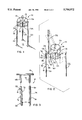
- FIG. 1 is a perspective view of a stand for supporting articles, according to the present invention, with the stand in an operative state and situated on a subjacent support surface;
- FIG. 2 is an exploded perspective view of the stand in FIG. 1 representing the disassembled state for the stand;
- FIG. 3 is an enlarged, fragmentary exploded, elevation view of one connection between a retainer ring and a base on the stand;
- FIG. 4 is an enlarged, fragmentary, partial cross-sectional view of one connection between a support shelf on the stand and the base;
- FIG. 5 is a schematic representation of a modified form of connection between the retainer ring and support shelf and the base, according to the present invention
- FIG. 6 is a view as in FIG. 5 of a still further modified form of connection according to the present invention.
- FIG. 7 cross-sectional view of a socket on the connection on a leg on the base taken along line 7--7 of FIG. 4.
- FIGS. 1-4 one form of stand, according to the present invention, is shown at 10 for supporting an article (not shown) in an elevated position on a subjacent support surface 12.
- the stand 10 consists of a shelf 14, defining an upwardly facing support surface 16 for an article, and a base 18. Structure cooperates between the base 18 and shelf 14 for allowing selective placement of the base 18 and shelf 14 in a) an operative state, as shown in FIG. 1 wherein the shelf 14 is stably supported on the base 18 so that the support surface 16 on the shelf 14 is in an elevated position relative to the surface 12, and b) a disassembled state, as shown in FIG. 2 wherein the shelf 14 is fully separated from the base 18.
- the base 18 is defined cooperatively by three legs 20, 22, 24 which are each releasably connected to the shelf 14 and a retainer ring 26.
- the exact number of legs is a design consideration.
- the retainer ring 26 is likewise placeable selectively in a) an operative state, as shown in FIG. 1 wherein the retainer ring 26 resides above the shelf 14 and extends at least partially around an article situated on the support surface 16 and b) a disassembled state, as shown in FIG. 2 wherein the retainer ring 26 is fully separated from the base 18.
- the legs 20, 22, 24 can be stacked, one on top of the other, and the shelf 14 and retainer ring 26 situated so that the outline of the stand 10 occupies a significantly lesser volume than it does in the operative state of FIG. 1.
- each of the shelf 14, retainer ring 26, and base 18 is made from formed wire.
- a suitable wire has a metal core with a plastic or rubber coating thereon.
- Each leg 20, 22, 24 has the same configuration.
- Representative leg 20 has an inverted U shape with first and second elongate, vertically extending elements 28, 30.
- the shelf 14 has a ring 32 spanned by straight wire elements 34, which cooperatively define the support surface 16 for an article.
- the retainer ring 26 is defined by a single wire formed into a circular shape.
- the retainer ring 26 and shelf 14 are each connected to the base 18 in such a manner that the shelf 14, retainer ring 26 and base 18 can be placed, and releasably maintained, in a predetermined relative position in the operative state without the need for separate fasteners and readily separated from each other.
- the shelf 14 is connected to each of the legs 20, 22, 24 in like fashion. Accordingly, the description herein will be limited to the representative connection between the shelf 14 and the leg 20.
- Each of the elongate elements 28, 30 has a socket 36, 38 thereon defining a cylindrical opening 40, 42 with a vertically extending axis 44, 46.
- a preferred embodiment of the socket 38 has a U-shaped cross section with legs 48, 50 which conform, and are suitably adhered, to the elongate element 30, as by welding or the use of an adhesive.
- the opening 42 is located in spaced relationship to the elongate element 30.
- the shelf 14 has cantilevered, depending posts, 52, 54 formed of wire to be received one each in the openings 40, 42 in the sockets 36, 38. As shown in FIG. 4, the central axes 44, 46 of the openings 40, 42 align with the lengths of the elongate elements 28, 30 and make a slight angle ⁇ with respect to each other.
- the central axes 56, 58 of the posts 52, 54 can be parallel to each other, make the angle ⁇ with respect to each other, or make another angle with respect to each other that is different than the angle ⁇ .
- the free ends 60, 62 of the posts 52, 54 are slightly misaligned with the upper entryways 64, 66 on the sockets 36, 38. This is a result of having the free ends 60, 62 spaced from each other either slightly greater or less than the spacing between the entryways 64, 66.
- the posts 52, 54 and/or the elongate elements 28, 30 with the sockets 36, 38 thereon must be reconfigured by moving them towards or away from each other to place them in an assembly state and thereby effect alignment between the posts 52, 54 and entryways 64, 66. This is permitted by the bendable nature of the wire defining the leg 20 and shelf 14.
- the reconfigured shelf 14 and/or leg 20 upon the posts 52, 54 being extended fully into the sockets 36, 38, tends to re-assume its normal, undeformed state and in so doing produces a residual gripping force between the posts 52, 54 and sockets 36, 38.
- the retainer ring 26 is also designed to be translated relative to the legs 20, 22, 24 to change the retainer ring 26 from the disassembled state in FIG. 2 to the operative state in FIG. 1.
- the retainer ring 26 has cantilevered posts 68, 70 made of wire and depending therefrom to project into openings 72, 74 defined by sockets 76, 78 on the elongate elements 28, 30.
- the posts 68, 70 are shown to be substantially parallel to each other to be press fit into the angularly oriented openings 72, 74 in the sockets 76, 78 in the same manner as the posts 52, 54 are directed into the openings 40, 42 in the sockets 36, 38.
- the posts 68, 70 and sockets 76, 78 by reason of being angularly misaligned, produce a torque on each other as the operative state is realized, and thereby enhance the frictional holding force therebetween.
- a similar connecting arrangement is provided between the retainer ring 26 and each of the other legs 22, 24.
- FIGS. 5 and 6 Various other relationships between the posts 52, 54; 68, 70 and sockets 36, 38; 76, 78 are contemplated, as shown schematically in FIGS. 5 and 6.
- the posts 52, 54; 68, 70 are parallel to each other.
- the central axes of the openings defined by the sockets 36, 38; 76, 78 are parallel to each other and the central axes of the posts 52, 54; 68, 70.
- the sockets 36, 38; 76, 78 must be shifted towards each other transversely to the length of the elongate elements 28, 30 to which they attach, as indicated by the arrows 80, 82, to allow the posts 52, 54; 68, 70 to be directed into the openings defined by the sockets 36, 38; 76, 78.
- the central axes of the posts 52, 54; 68, 70 are at an angle ⁇ with respect to each other, with the central axes of the openings defined by the sockets 36, 38; 76, 78 being at an angle ⁇ 1 with respect to each other.
- the angles ⁇ , ⁇ 1 can be the same or different. In either event, deformation of the posts 52, 54; 68, 70 and/or the elongate elements 28, 30 is required to effect full seating of the posts 52, 54; 68, 70 in the openings defined by the sockets 36, 38; 76, 78.
- the invention also contemplates that with the exemplary connection between the leg 20 and shelf 14, two posts, one post and one socket, or two sockets can be provided on each of the shelf 14 and leg 20. A similar arrangement is contemplated for the connection between the retainer ring 26 and the leg 20.
- the shelf 14, retainer ring 26 and base 18 can be consistently placed in the operative state of FIG. 1 and securely, releasably held in that state.
- the shelf 14, retainer ring 26 and base 18 are allowed to be relatively translated from the disassembled state into the operative state and frictionally maintained in that state without the need for separate fasteners. Separate fasteners could be employed to enhance the connection between these elements.
- the shelf 14, retainer ring 26 and base 18 could be aligned in the disassembled state and placed in the operative state without any, or any significant, deformation of any of these elements.
Landscapes
- Assembled Shelves (AREA)
Abstract
Description
Claims (18)
Priority Applications (1)
| Application Number | Priority Date | Filing Date | Title |
|---|---|---|---|
| US08/714,187 US5784972A (en) | 1996-09-16 | 1996-09-16 | Stand for supporting articles |
Applications Claiming Priority (1)
| Application Number | Priority Date | Filing Date | Title |
|---|---|---|---|
| US08/714,187 US5784972A (en) | 1996-09-16 | 1996-09-16 | Stand for supporting articles |
Publications (1)
| Publication Number | Publication Date |
|---|---|
| US5784972A true US5784972A (en) | 1998-07-28 |
Family
ID=24869061
Family Applications (1)
| Application Number | Title | Priority Date | Filing Date |
|---|---|---|---|
| US08/714,187 Expired - Lifetime US5784972A (en) | 1996-09-16 | 1996-09-16 | Stand for supporting articles |
Country Status (1)
| Country | Link |
|---|---|
| US (1) | US5784972A (en) |
Cited By (16)
| Publication number | Priority date | Publication date | Assignee | Title |
|---|---|---|---|---|
| USD442677S1 (en) | 2000-04-06 | 2001-05-22 | Kohler Co. | Stand |
| USD443043S1 (en) | 2000-04-05 | 2001-05-29 | Kohler Co. | Stand |
| US20030033750A1 (en) * | 2001-08-16 | 2003-02-20 | Gunderman John E. | Wire cage for nursery items |
| US6578802B1 (en) | 2001-06-22 | 2003-06-17 | Steven E. Thier | Water cooler support device |
| US8215497B1 (en) * | 2011-05-03 | 2012-07-10 | Robert Bernard Marchalonis | Collapsible stand |
| US20160213195A1 (en) * | 2015-01-26 | 2016-07-28 | Bernet Ulysses Revely, III | Semi Automatic Collapsible Chafer with Heater Supports |
| US9541231B1 (en) | 2013-06-22 | 2017-01-10 | Celena Misshola Owens | Frame support for creating and displaying handmade paper crafts |
| USD794375S1 (en) * | 2016-01-19 | 2017-08-15 | Fuji Kouki Co., Ltd. | Coffee maker |
| US10295130B1 (en) | 2014-06-23 | 2019-05-21 | Celena Misshola Owens | Frame support for handmade paper crafts and lanterns |
| USD941603S1 (en) * | 2019-06-25 | 2022-01-25 | Metro Decor, LLC | Stand |
| US11553820B1 (en) * | 2020-06-25 | 2023-01-17 | Stevie Cheyenne Alexander | Piping bag stand |
| USD978584S1 (en) * | 2021-01-27 | 2023-02-21 | Zhanlei Zhao | Shelf |
| US20230150809A1 (en) * | 2021-11-17 | 2023-05-18 | Charles Y. Yu | Modular Dispenser Stand |
| USD1047758S1 (en) * | 2021-11-18 | 2024-10-22 | Marly Garden LLC | Planter |
| US20250018263A1 (en) * | 2023-07-12 | 2025-01-16 | Trisha Woolen Investments Inc. | Fill material dispenser |
| USD1102317S1 (en) * | 2023-10-18 | 2025-11-18 | Floracraft Corporation | Floral arranging device |
Citations (14)
| Publication number | Priority date | Publication date | Assignee | Title |
|---|---|---|---|---|
| FR674881A (en) * | 1929-05-10 | 1930-02-03 | S O D | Removable table |
| US2768044A (en) * | 1955-09-16 | 1956-10-23 | Jaffe Jerome | Table leg construction |
| US2828175A (en) * | 1956-05-03 | 1958-03-25 | Ada Metal Products Inc | Knock-down furniture |
| GB856392A (en) * | 1957-10-28 | 1960-12-14 | Grythyttans Stalmoebler Ab | Improvements in and relating to loading pallets |
| FR74567E (en) * | 1958-11-28 | 1960-12-19 | Assembly part for tubular legs of tables, chairs and other furniture and its manufacturing process | |
| FR1425784A (en) * | 1965-02-25 | 1966-01-24 | Method and arrangements for assembling elements of tables, television tables and other furniture | |
| CH427169A (en) * | 1963-05-17 | 1966-12-31 | Hein Piet | Furniture leg |
| US3316864A (en) * | 1963-03-01 | 1967-05-02 | Maslow Louis | Knockdown shelving unit |
| US3696763A (en) * | 1970-05-04 | 1972-10-10 | Metals Inc | Stock rack |
| USRE28244E (en) * | 1970-05-04 | 1974-11-19 | Stock rack | |
| US4338867A (en) * | 1980-02-11 | 1982-07-13 | Ray Control Corp. | Table assembled without fasteners |
| US4627543A (en) * | 1985-06-25 | 1986-12-09 | United Steel & Wire Company | Compression sleeve corner structure for adjustable shelving |
| US4901959A (en) * | 1988-07-26 | 1990-02-20 | Stage Jack W | Collapsible support stand for flexible trash bag |
| US5287800A (en) * | 1990-08-20 | 1994-02-22 | Orednick J Paul | Caterer food display system |
-
1996
- 1996-09-16 US US08/714,187 patent/US5784972A/en not_active Expired - Lifetime
Patent Citations (14)
| Publication number | Priority date | Publication date | Assignee | Title |
|---|---|---|---|---|
| FR674881A (en) * | 1929-05-10 | 1930-02-03 | S O D | Removable table |
| US2768044A (en) * | 1955-09-16 | 1956-10-23 | Jaffe Jerome | Table leg construction |
| US2828175A (en) * | 1956-05-03 | 1958-03-25 | Ada Metal Products Inc | Knock-down furniture |
| GB856392A (en) * | 1957-10-28 | 1960-12-14 | Grythyttans Stalmoebler Ab | Improvements in and relating to loading pallets |
| FR74567E (en) * | 1958-11-28 | 1960-12-19 | Assembly part for tubular legs of tables, chairs and other furniture and its manufacturing process | |
| US3316864A (en) * | 1963-03-01 | 1967-05-02 | Maslow Louis | Knockdown shelving unit |
| CH427169A (en) * | 1963-05-17 | 1966-12-31 | Hein Piet | Furniture leg |
| FR1425784A (en) * | 1965-02-25 | 1966-01-24 | Method and arrangements for assembling elements of tables, television tables and other furniture | |
| US3696763A (en) * | 1970-05-04 | 1972-10-10 | Metals Inc | Stock rack |
| USRE28244E (en) * | 1970-05-04 | 1974-11-19 | Stock rack | |
| US4338867A (en) * | 1980-02-11 | 1982-07-13 | Ray Control Corp. | Table assembled without fasteners |
| US4627543A (en) * | 1985-06-25 | 1986-12-09 | United Steel & Wire Company | Compression sleeve corner structure for adjustable shelving |
| US4901959A (en) * | 1988-07-26 | 1990-02-20 | Stage Jack W | Collapsible support stand for flexible trash bag |
| US5287800A (en) * | 1990-08-20 | 1994-02-22 | Orednick J Paul | Caterer food display system |
Cited By (19)
| Publication number | Priority date | Publication date | Assignee | Title |
|---|---|---|---|---|
| USD443043S1 (en) | 2000-04-05 | 2001-05-29 | Kohler Co. | Stand |
| USD442677S1 (en) | 2000-04-06 | 2001-05-22 | Kohler Co. | Stand |
| US6578802B1 (en) | 2001-06-22 | 2003-06-17 | Steven E. Thier | Water cooler support device |
| US20030033750A1 (en) * | 2001-08-16 | 2003-02-20 | Gunderman John E. | Wire cage for nursery items |
| US6895712B2 (en) * | 2001-08-16 | 2005-05-24 | Cherokee Manufacturing, Inc. | Wire cage for nursery items |
| US8215497B1 (en) * | 2011-05-03 | 2012-07-10 | Robert Bernard Marchalonis | Collapsible stand |
| US9541231B1 (en) | 2013-06-22 | 2017-01-10 | Celena Misshola Owens | Frame support for creating and displaying handmade paper crafts |
| US10295130B1 (en) | 2014-06-23 | 2019-05-21 | Celena Misshola Owens | Frame support for handmade paper crafts and lanterns |
| US10478014B2 (en) * | 2015-01-26 | 2019-11-19 | Bernet Ulysses Revely, III | Semi automatic collapsible chafer with heater supports |
| US20160213195A1 (en) * | 2015-01-26 | 2016-07-28 | Bernet Ulysses Revely, III | Semi Automatic Collapsible Chafer with Heater Supports |
| USD794375S1 (en) * | 2016-01-19 | 2017-08-15 | Fuji Kouki Co., Ltd. | Coffee maker |
| USD941603S1 (en) * | 2019-06-25 | 2022-01-25 | Metro Decor, LLC | Stand |
| US11553820B1 (en) * | 2020-06-25 | 2023-01-17 | Stevie Cheyenne Alexander | Piping bag stand |
| USD978584S1 (en) * | 2021-01-27 | 2023-02-21 | Zhanlei Zhao | Shelf |
| US20230150809A1 (en) * | 2021-11-17 | 2023-05-18 | Charles Y. Yu | Modular Dispenser Stand |
| US11970384B2 (en) * | 2021-11-17 | 2024-04-30 | Charles Y. Yu | Modular dispenser stand |
| USD1047758S1 (en) * | 2021-11-18 | 2024-10-22 | Marly Garden LLC | Planter |
| US20250018263A1 (en) * | 2023-07-12 | 2025-01-16 | Trisha Woolen Investments Inc. | Fill material dispenser |
| USD1102317S1 (en) * | 2023-10-18 | 2025-11-18 | Floracraft Corporation | Floral arranging device |
Similar Documents
| Publication | Publication Date | Title |
|---|---|---|
| US5784972A (en) | Stand for supporting articles | |
| US4688684A (en) | Vertical display system | |
| US5215199A (en) | Rack for supporting items such as bottles | |
| US4193351A (en) | Display rack assembly | |
| US4653651A (en) | Stackable shelving system | |
| US4747644A (en) | Portable display stand | |
| CA2026445C (en) | Article organizer display unit | |
| US4356923A (en) | Storage and dispensing rack | |
| US4969618A (en) | Container holder | |
| US4878586A (en) | Rack and tube member for organizing electrical cords | |
| US4453640A (en) | Adjustable, sectional display device | |
| US9247834B1 (en) | Shelf locking structure for display rack | |
| US4750623A (en) | Stackable shelving system | |
| US20040020878A1 (en) | Product display rack | |
| US3787018A (en) | Base for an upright for forming a stand or the like | |
| US8985351B1 (en) | Display device | |
| US10238208B2 (en) | Modular food product display stand | |
| US4172334A (en) | Display and stocking stands | |
| US4289246A (en) | Free standing merchandiser | |
| US4403702A (en) | Variable display merchandising rack | |
| US4964520A (en) | Display assembly | |
| US6457595B1 (en) | Configurable shelving/storage system | |
| US20040182810A1 (en) | Stackable shelf | |
| US4270463A (en) | Display stand with easily adjusted shelves | |
| US2993604A (en) | Display stand |
Legal Events
| Date | Code | Title | Description |
|---|---|---|---|
| STCF | Information on status: patent grant |
Free format text: PATENTED CASE |
|
| FPAY | Fee payment |
Year of fee payment: 4 |
|
| REMI | Maintenance fee reminder mailed | ||
| REMI | Maintenance fee reminder mailed | ||
| FPAY | Fee payment |
Year of fee payment: 8 |
|
| SULP | Surcharge for late payment |
Year of fee payment: 7 |
|
| AS | Assignment |
Owner name: COBRACO MANUFACTURING, INC., ILLINOIS Free format text: ASSIGNMENT OF ASSIGNORS INTEREST;ASSIGNORS:EMALFARB, BRADLEY;EMALFARB, SEYMOUR;REEL/FRAME:020817/0639 Effective date: 20080416 |
|
| AS | Assignment |
Owner name: ANTARES CAPITAL CORPORATION, ILLINOIS Free format text: SECURITY AGREEMENT;ASSIGNOR:COBRACO MANUFACTURING, INC.;REEL/FRAME:020828/0482 Effective date: 20080417 |
|
| AS | Assignment |
Owner name: COBRACO MANUFACTURING, INC., ILLINOIS Free format text: CORRECTIVE ASSIGNMENT TO CORRECT THE EXECUTION DATE OF DOCUMENT. PREVIOUSLY RECORDED ON REEL 020817 FRAME 0639. ASSIGNOR(S) HEREBY CONFIRMS THE EXECUTION DATE OF DOCUMENT..;ASSIGNORS:EMALFARB, BRADLEY;EMALFARB, SEYMOUR;REEL/FRAME:020866/0451 Effective date: 20080414 |
|
| AS | Assignment |
Owner name: WOODSTREAM CORPORATION, PENNSYLVANIA Free format text: ASSIGNMENT OF ASSIGNORS INTEREST;ASSIGNOR:COBRACO MANUFACTURING, INC.;REEL/FRAME:020951/0662 Effective date: 20080417 |
|
| AS | Assignment |
Owner name: COBRACO MANUFACTURING, INC., ILLINOIS Free format text: ASSIGNMENT OF ASSIGNORS INTEREST;ASSIGNORS:EMALFARB, BRADLEY;EMALFARB, SEYMOUR;REEL/FRAME:021450/0354 Effective date: 20080716 Owner name: COBRACO MANUFACTURING, INC., ILLINOIS Free format text: ASSIGNMENT OF ASSIGNORS INTEREST;ASSIGNORS:EMALFARB, BRADLEY;EMALFARB, SEYMOUR;REEL/FRAME:021339/0319 Effective date: 20080716 |
|
| AS | Assignment |
Owner name: WOODSTREAM CORPORATION, PENNSYLVANIA Free format text: ASSIGNMENT OF ASSIGNORS INTEREST;ASSIGNOR:COBRACO MANUFACTURING, INC.;REEL/FRAME:021266/0908 Effective date: 20080716 |
|
| FPAY | Fee payment |
Year of fee payment: 12 |
|
| AS | Assignment |
Owner name: ANTARES CAPITAL CORPORATION, AS ADMINISTRATIVE AGE Free format text: SECURITY AGREEMENT;ASSIGNOR:WOODSTREAM CORPORATION;REEL/FRAME:028050/0481 Effective date: 20120413 |
|
| AS | Assignment |
Owner name: GENERAL ELECTRIC CAPITAL CORPORATION, AS COLLATERAL AGENT, ILLINOIS Free format text: SECURITY INTEREST;ASSIGNOR:WOODSTREAM CORPORATION;REEL/FRAME:035861/0104 Effective date: 20150529 Owner name: GENERAL ELECTRIC CAPITAL CORPORATION, AS COLLATERA Free format text: SECURITY INTEREST;ASSIGNOR:WOODSTREAM CORPORATION;REEL/FRAME:035861/0104 Effective date: 20150529 |
|
| AS | Assignment |
Owner name: MIDWEST AIR TECHNOLOGIES, INC., ILLINOIS Free format text: ASSIGNMENT OF ASSIGNORS INTEREST;ASSIGNOR:WOODSTREAM CORPORATION;REEL/FRAME:039870/0132 Effective date: 20160912 |
|
| AS | Assignment |
Owner name: WOODSTREAM CORPORATION, PENNSYLVANIA Free format text: RELEASE OF SECURITY INTEREST RECORDED AT REEL/FRAME 28050/0481;ASSIGNOR:ANTARES CAPITAL CORPORATION;REEL/FRAME:043031/0406 Effective date: 20150529 |
|
| AS | Assignment |
Owner name: WOODSTREAM CORPORATION, PENNSYLVANIA Free format text: RELEASE OF SECURITY INTEREST RECORDED AT REEL/FRAME 035861/0104;ASSIGNOR:GENERAL ELECTRIC COMPANY;REEL/FRAME:043181/0195 Effective date: 20170621 |