US5771990A - Shock absorbing foot means - Google Patents
Shock absorbing foot means Download PDFInfo
- Publication number
- US5771990A US5771990A US08/845,403 US84540397A US5771990A US 5771990 A US5771990 A US 5771990A US 84540397 A US84540397 A US 84540397A US 5771990 A US5771990 A US 5771990A
- Authority
- US
- United States
- Prior art keywords
- receptacle
- rounded recess
- open chamber
- base
- mounting plate
- Prior art date
- Legal status (The legal status is an assumption and is not a legal conclusion. Google has not performed a legal analysis and makes no representation as to the accuracy of the status listed.)
- Expired - Fee Related
Links
- 230000035939 shock Effects 0.000 title claims abstract description 17
- 239000000853 adhesive Substances 0.000 claims description 6
- 230000001070 adhesive effect Effects 0.000 claims description 6
- 238000012986 modification Methods 0.000 description 1
- 230000004048 modification Effects 0.000 description 1
Images


Classifications
-
- F—MECHANICAL ENGINEERING; LIGHTING; HEATING; WEAPONS; BLASTING
- F16—ENGINEERING ELEMENTS AND UNITS; GENERAL MEASURES FOR PRODUCING AND MAINTAINING EFFECTIVE FUNCTIONING OF MACHINES OR INSTALLATIONS; THERMAL INSULATION IN GENERAL
- F16F—SPRINGS; SHOCK-ABSORBERS; MEANS FOR DAMPING VIBRATION
- F16F15/00—Suppression of vibrations in systems; Means or arrangements for avoiding or reducing out-of-balance forces, e.g. due to motion
- F16F15/02—Suppression of vibrations of non-rotating, e.g. reciprocating systems; Suppression of vibrations of rotating systems by use of members not moving with the rotating systems
- F16F15/021—Decoupling of vibrations by means of point-of-contact supports, e.g. ball bearings
-
- F—MECHANICAL ENGINEERING; LIGHTING; HEATING; WEAPONS; BLASTING
- F16—ENGINEERING ELEMENTS AND UNITS; GENERAL MEASURES FOR PRODUCING AND MAINTAINING EFFECTIVE FUNCTIONING OF MACHINES OR INSTALLATIONS; THERMAL INSULATION IN GENERAL
- F16F—SPRINGS; SHOCK-ABSORBERS; MEANS FOR DAMPING VIBRATION
- F16F15/00—Suppression of vibrations in systems; Means or arrangements for avoiding or reducing out-of-balance forces, e.g. due to motion
- F16F15/02—Suppression of vibrations of non-rotating, e.g. reciprocating systems; Suppression of vibrations of rotating systems by use of members not moving with the rotating systems
-
- F—MECHANICAL ENGINEERING; LIGHTING; HEATING; WEAPONS; BLASTING
- F16—ENGINEERING ELEMENTS AND UNITS; GENERAL MEASURES FOR PRODUCING AND MAINTAINING EFFECTIVE FUNCTIONING OF MACHINES OR INSTALLATIONS; THERMAL INSULATION IN GENERAL
- F16F—SPRINGS; SHOCK-ABSORBERS; MEANS FOR DAMPING VIBRATION
- F16F7/00—Vibration-dampers; Shock-absorbers
Definitions
- the present invention relates to a shock absorbing foot used to support an audio equipment on a floor surface or table top, and more particularly to such a shock absorbing foot which effectively absorbs shocks during the operation of the audio equipment.
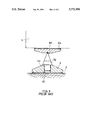
- FIG. 3 shows a shock absorbing foot adapted for supporting an audio equipment 4 on a floor surface 5.
- the shock absorbing foot comprises a base 6 having a vertical center screw hole 61, a mounting plate 64 fixedly fastened to the bottom side of the audio equipment 4 and having a rounded recess 65 at the center of its bottom side, and an arrowhead support member 62 having a bottom screw rod 63 threaded into the vertical center screw hole 61 of the base 6 and a top point engaging the rounded recess 65 of the mounting plate 64.
- shock absorbing foot is not practical for use with a high power audio equipment because the arrowhead support member 62 cannot be oscillated within the base 6 to lessen shocks, shocks tend to be transmitted from the audio equipment 4 to the floor surface 5, causing a noise or resonance to be produced.
- the present invention provides a shock absorbing foot adapted for supporting an audio equipment on a flat surface which effectively absorbs shocks.
- the shock absorbing foot comprises a base shaped like a truncated cone having a bottom side adhered to a flat surface by a double-sided adhesive pad, and a vertical screw hole at the center of a top side thereof; a receptacle shaped like a headed, cylindrical container and mounted on the base, the receptacle comprising an outer thread threaded into the screw hole of the base, a top open chamber having a horizontal bottom wall, and a rounded recess at the center of the horizontal bottom wall of the top open chamber; a mounting plate having a top side fastened to a bottom side of an audio equipment by a double-sided adhesive pad, a bottom side facing said base, and a rounded recess at the center of its bottom side; and a support member mounted in the top open chamber of the receptacle to support the mounting plate, the support member comprising a hexagonal flank,
- FIG. 1 is an exploded view of a shock absorbing foot for audio equipment according to the present invention
- FIG. 2 is an installed view in section of the present invention.
- FIG. 3 is an installed view in section of a shock absorbing foot according to the prior art.
- the present invention is adapted to be fastened to a bottom side of a high power audio equipment for supporting it on a floor surface or table top, comprised of a base 1, a mounting plate 3, a receptacle 12, and a support member 2.
- the base 1 is shaped like a truncated cone having a bottom side adhered to for example the floor 5 by a double-sided adhesive pad 13, and a vertical screw hole 11 at its top center.
- the receptacle 12 is shaped like a headed, cylindrical container, comprising an outer thread 121 threaded into the screw hole 11, a top open chamber 122, a rounded recess 12 at the center of the bottom wall of the top open chamber 122.
- the mounting plate 3 is fastened to a bottom side of an audio equipment 4 by a double-sided adhesive pad 32, having a rounded recess 31 at the center of its bottom side.
- the support member 2 is mounted in the top open chamber 122 of the receptacle 12 to support the mounting plate 3, having a hexagonal flank 21, a plurality of projecting portions 22 equiangularly spaced around the periphery of the hexagonal flank 21 and disposed in contact with the periphery of the top open chamber 122 of the receptacle 12, and two cones 23 at two opposite sides respectively engaging the rounded recess 31 of the mounting plate 3 and the rounded recess 123 of the receptacle 12.
- the support member 2 has the pointed tips of its cones 23 respectively engaging the rounded recess 31 of the mounting plate 3 and the rounded recess 123 of the receptacle 12, and the projecting portions 22 of its flank 21 disposed in contact with the periphery of the top open chamber 122 of the receptacle 12, it will be forced to vibrate during the operation of the audio equipment 4, causing shock waves that come from the audio equipment 4 to be absorbed or lessened.
Landscapes
- Engineering & Computer Science (AREA)
- General Engineering & Computer Science (AREA)
- Mechanical Engineering (AREA)
- Physics & Mathematics (AREA)
- Acoustics & Sound (AREA)
- Aviation & Aerospace Engineering (AREA)
- Casings For Electric Apparatus (AREA)
- Details Of Audible-Bandwidth Transducers (AREA)
- Vibration Dampers (AREA)
Abstract
A shock absorbing foot adapted for supporting an audio equipment on a flat surface, including a base adhered to a flat surface and having a top screw hole, a mounting plate adhered to a bottom side of an audio equipment and having a rounded recess at its bottom center, a receptacle threaded into the top screw hole of the base and having a top open chamber and a rounded recess at the center of the bottom of the top open chamber, and a support member having a plurality of projecting portions disposed in contact with the periphery of the top open chamber and two cones respectively engaging the rounded recess of the mounting plate and the rounded recess of the receptacle.
Description
The present invention relates to a shock absorbing foot used to support an audio equipment on a floor surface or table top, and more particularly to such a shock absorbing foot which effectively absorbs shocks during the operation of the audio equipment.
FIG. 3 shows a shock absorbing foot adapted for supporting an audio equipment 4 on a floor surface 5. The shock absorbing foot comprises a base 6 having a vertical center screw hole 61, a mounting plate 64 fixedly fastened to the bottom side of the audio equipment 4 and having a rounded recess 65 at the center of its bottom side, and an arrowhead support member 62 having a bottom screw rod 63 threaded into the vertical center screw hole 61 of the base 6 and a top point engaging the rounded recess 65 of the mounting plate 64. This structure of shock absorbing foot is not practical for use with a high power audio equipment because the arrowhead support member 62 cannot be oscillated within the base 6 to lessen shocks, shocks tend to be transmitted from the audio equipment 4 to the floor surface 5, causing a noise or resonance to be produced.
The present invention provides a shock absorbing foot adapted for supporting an audio equipment on a flat surface which effectively absorbs shocks. The shock absorbing foot comprises a base shaped like a truncated cone having a bottom side adhered to a flat surface by a double-sided adhesive pad, and a vertical screw hole at the center of a top side thereof; a receptacle shaped like a headed, cylindrical container and mounted on the base, the receptacle comprising an outer thread threaded into the screw hole of the base, a top open chamber having a horizontal bottom wall, and a rounded recess at the center of the horizontal bottom wall of the top open chamber; a mounting plate having a top side fastened to a bottom side of an audio equipment by a double-sided adhesive pad, a bottom side facing said base, and a rounded recess at the center of its bottom side; and a support member mounted in the top open chamber of the receptacle to support the mounting plate, the support member comprising a hexagonal flank, a plurality of projecting portions equiangularly spaced around the periphery of the hexagonal flank and disposed in contact with the periphery of the top open chamber of the receptacle, a top cone having a top point engaging the rounded recess of the mounting plate, and a bottom cone having a bottom point engaging the rounded recess of the receptacle.
FIG. 1 is an exploded view of a shock absorbing foot for audio equipment according to the present invention;
FIG. 2 is an installed view in section of the present invention; and
FIG. 3 is an installed view in section of a shock absorbing foot according to the prior art.
Referring to FIGS. 1 and 2, the present invention is adapted to be fastened to a bottom side of a high power audio equipment for supporting it on a floor surface or table top, comprised of a base 1, a mounting plate 3, a receptacle 12, and a support member 2. The base 1 is shaped like a truncated cone having a bottom side adhered to for example the floor 5 by a double-sided adhesive pad 13, and a vertical screw hole 11 at its top center. The receptacle 12 is shaped like a headed, cylindrical container, comprising an outer thread 121 threaded into the screw hole 11, a top open chamber 122, a rounded recess 12 at the center of the bottom wall of the top open chamber 122. The mounting plate 3 is fastened to a bottom side of an audio equipment 4 by a double-sided adhesive pad 32, having a rounded recess 31 at the center of its bottom side. The support member 2 is mounted in the top open chamber 122 of the receptacle 12 to support the mounting plate 3, having a hexagonal flank 21, a plurality of projecting portions 22 equiangularly spaced around the periphery of the hexagonal flank 21 and disposed in contact with the periphery of the top open chamber 122 of the receptacle 12, and two cones 23 at two opposite sides respectively engaging the rounded recess 31 of the mounting plate 3 and the rounded recess 123 of the receptacle 12.
Referring to FIG. 2 again, because the support member 2 has the pointed tips of its cones 23 respectively engaging the rounded recess 31 of the mounting plate 3 and the rounded recess 123 of the receptacle 12, and the projecting portions 22 of its flank 21 disposed in contact with the periphery of the top open chamber 122 of the receptacle 12, it will be forced to vibrate during the operation of the audio equipment 4, causing shock waves that come from the audio equipment 4 to be absorbed or lessened.
While only one embodiment of the present invention has been shown and described, it will be understood that various modifications and changes could be made thereunto without departing from the spirit and scope of the invention disclosed.
Claims (1)
1. A shock absorbing foot adapted for supporting an audio equipment on a flat surface, comprising:
a base shaped like a truncated cone having a bottom side adhered to a flat surface by a double-sided adhesive pad, and a vertical screw hole at the center of a top side thereof;
a receptacle shaped like a headed, cylindrical container and mounted on said base, said receptacle comprising an outer thread threaded into the screw hole of said base, a top open chamber having a horizontal bottom wall, and a rounded recess at the center of the horizontal bottom wall of said top open chamber;
a mounting plate having a top side fastened to a bottom side of an audio equipment by a double-sided adhesive pad, a bottom side facing said base, and a rounded recess at the center of its bottom side; and
a support member mounted in the top open chamber of said receptacle to support said mounting plate, said support member comprising a hexagonal flank, a plurality of projecting portions equiangularly spaced around the periphery of said hexagonal flank and disposed in contact with the periphery of the top open chamber of said receptacle, a top cone having a top point engaging the rounded recess of said mounting plate, and a bottom cone having a bottom point engaging the rounded recess of said receptacle.
Priority Applications (1)
| Application Number | Priority Date | Filing Date | Title |
|---|---|---|---|
| US08/845,403 US5771990A (en) | 1997-04-25 | 1997-04-25 | Shock absorbing foot means |
Applications Claiming Priority (1)
| Application Number | Priority Date | Filing Date | Title |
|---|---|---|---|
| US08/845,403 US5771990A (en) | 1997-04-25 | 1997-04-25 | Shock absorbing foot means |
Publications (1)
| Publication Number | Publication Date |
|---|---|
| US5771990A true US5771990A (en) | 1998-06-30 |
Family
ID=25295160
Family Applications (1)
| Application Number | Title | Priority Date | Filing Date |
|---|---|---|---|
| US08/845,403 Expired - Fee Related US5771990A (en) | 1997-04-25 | 1997-04-25 | Shock absorbing foot means |
Country Status (1)
| Country | Link |
|---|---|
| US (1) | US5771990A (en) |
Cited By (19)
| Publication number | Priority date | Publication date | Assignee | Title |
|---|---|---|---|---|
| US5942735A (en) * | 1998-09-15 | 1999-08-24 | Liang; Shih-Tsung | Shock absorbing foot means adapted for supporting an audio equipment on a flat surface |
| US6138979A (en) * | 1999-01-28 | 2000-10-31 | Morman; Lawrence M. | Isolating foot pad |
| US6439519B1 (en) * | 2000-07-06 | 2002-08-27 | Sony Computer Entertainment, Inc. | Case assembly including legs and caps |
| US20030155480A1 (en) * | 2002-02-18 | 2003-08-21 | Andrzej Cholinski | Support of a drive unit for a lift |
| US20030218957A1 (en) * | 2002-03-11 | 2003-11-27 | Takao Tanishima | Support leg device for equipment case |
| USD511636S1 (en) | 2004-02-06 | 2005-11-22 | O'sullivan Industries, Inc. | Furniture leg |
| US20060083585A1 (en) * | 2002-07-25 | 2006-04-20 | Cooper Technology Services, Llc | Break-away cradle or sub-frame mount and retainer washer assembly |
| US20060147080A1 (en) * | 2004-12-31 | 2006-07-06 | Wilson David A | Magnetized attachment system for cones and other placement and coupling accessories |
| US20070176073A1 (en) * | 2006-01-30 | 2007-08-02 | Mark Simic | Dynamic Mouse Tray |
| GB2437360A (en) * | 2006-04-18 | 2007-10-24 | Christopher Mark Guest | Sound equipment vibration damper |
| US20080185183A1 (en) * | 2007-02-07 | 2008-08-07 | Chien-Chung Chen | Resonance-coordinating device for audio and video |
| US20120097828A1 (en) * | 2010-10-21 | 2012-04-26 | Burns Martin P | Resilient foot |
| US8833511B2 (en) * | 2010-07-30 | 2014-09-16 | Tokkyokiki Corporation | Insulator for audio and method for evaluating same |
| US10187712B2 (en) * | 2015-05-13 | 2019-01-22 | Michael P. Latvis, Jr. | Energy dissipation devices |
| CN110332152A (en) * | 2019-08-07 | 2019-10-15 | 江西书源科技有限公司 | A kind of shock-damping structure of water purifier water pump and shell |
| US10971126B1 (en) * | 2020-01-08 | 2021-04-06 | Wilson Audio Specialties, Inc. | Vibration damper |
| RU2751292C1 (en) * | 2021-01-22 | 2021-07-12 | Сергей Антонович Васильев | Support unit of radio electronic device and support leg for radio electronic device |
| US20240167265A1 (en) * | 2022-11-22 | 2024-05-23 | Advanced Architectural Products, Llc | Bracket assembly, shim member for use with a bracket member and methods of assembly and use |
| WO2024158059A1 (en) * | 2023-01-29 | 2024-08-02 | 慶應義塾 | Antivibration device, jig for antivibration, and antivibration system |
Citations (6)
| Publication number | Priority date | Publication date | Assignee | Title |
|---|---|---|---|---|
| EP0159001A2 (en) * | 1984-04-19 | 1985-10-23 | Erich Munz | Supporting and damping device adjustable in height |
| US4880077A (en) * | 1988-03-08 | 1989-11-14 | Gisbert Verse | Base for a loudspeaker enclosure |
| US5210383A (en) * | 1991-07-22 | 1993-05-11 | Noxon Arthur M | Sound absorbent device for a room |
| US5344116A (en) * | 1991-11-27 | 1994-09-06 | Ymos Aktiengesellschaft Industrieprodukte | Foot for an appliance, such as a washing machine |
| US5570867A (en) * | 1995-09-18 | 1996-11-05 | Illinois Tool Works, Inc. | Shock mount assembly |
| US5710396A (en) * | 1996-01-02 | 1998-01-20 | Rogers; Lynn C. | Energy-dissipating vibration damping structure |
-
1997
- 1997-04-25 US US08/845,403 patent/US5771990A/en not_active Expired - Fee Related
Patent Citations (6)
| Publication number | Priority date | Publication date | Assignee | Title |
|---|---|---|---|---|
| EP0159001A2 (en) * | 1984-04-19 | 1985-10-23 | Erich Munz | Supporting and damping device adjustable in height |
| US4880077A (en) * | 1988-03-08 | 1989-11-14 | Gisbert Verse | Base for a loudspeaker enclosure |
| US5210383A (en) * | 1991-07-22 | 1993-05-11 | Noxon Arthur M | Sound absorbent device for a room |
| US5344116A (en) * | 1991-11-27 | 1994-09-06 | Ymos Aktiengesellschaft Industrieprodukte | Foot for an appliance, such as a washing machine |
| US5570867A (en) * | 1995-09-18 | 1996-11-05 | Illinois Tool Works, Inc. | Shock mount assembly |
| US5710396A (en) * | 1996-01-02 | 1998-01-20 | Rogers; Lynn C. | Energy-dissipating vibration damping structure |
Cited By (27)
| Publication number | Priority date | Publication date | Assignee | Title |
|---|---|---|---|---|
| US5942735A (en) * | 1998-09-15 | 1999-08-24 | Liang; Shih-Tsung | Shock absorbing foot means adapted for supporting an audio equipment on a flat surface |
| US6138979A (en) * | 1999-01-28 | 2000-10-31 | Morman; Lawrence M. | Isolating foot pad |
| US6439519B1 (en) * | 2000-07-06 | 2002-08-27 | Sony Computer Entertainment, Inc. | Case assembly including legs and caps |
| US6659411B2 (en) * | 2000-07-06 | 2003-12-09 | Sony Computer Entertainment Inc. | Case assembly including legs and caps |
| US20030155480A1 (en) * | 2002-02-18 | 2003-08-21 | Andrzej Cholinski | Support of a drive unit for a lift |
| US6729597B2 (en) * | 2002-02-18 | 2004-05-04 | Inventio Ag | Support of a drive unit for a lift |
| US20030218957A1 (en) * | 2002-03-11 | 2003-11-27 | Takao Tanishima | Support leg device for equipment case |
| US7048247B2 (en) * | 2002-03-11 | 2006-05-23 | Teac Corporation | Support leg device for equipment case |
| US20060083585A1 (en) * | 2002-07-25 | 2006-04-20 | Cooper Technology Services, Llc | Break-away cradle or sub-frame mount and retainer washer assembly |
| USD511636S1 (en) | 2004-02-06 | 2005-11-22 | O'sullivan Industries, Inc. | Furniture leg |
| USD516344S1 (en) | 2004-02-06 | 2006-03-07 | O'sullivan Industries, Inc. | Furniture leg |
| US20060147080A1 (en) * | 2004-12-31 | 2006-07-06 | Wilson David A | Magnetized attachment system for cones and other placement and coupling accessories |
| US20070176073A1 (en) * | 2006-01-30 | 2007-08-02 | Mark Simic | Dynamic Mouse Tray |
| US7527234B2 (en) * | 2006-01-30 | 2009-05-05 | Mark Simic | Dynamic mouse tray |
| GB2437360A (en) * | 2006-04-18 | 2007-10-24 | Christopher Mark Guest | Sound equipment vibration damper |
| US20080185183A1 (en) * | 2007-02-07 | 2008-08-07 | Chien-Chung Chen | Resonance-coordinating device for audio and video |
| EP2600348A4 (en) * | 2010-07-30 | 2018-01-24 | Tokkyokiki Corporation | Insulator for audio and method for evaluating same |
| US8833511B2 (en) * | 2010-07-30 | 2014-09-16 | Tokkyokiki Corporation | Insulator for audio and method for evaluating same |
| US20120097828A1 (en) * | 2010-10-21 | 2012-04-26 | Burns Martin P | Resilient foot |
| US9765919B2 (en) * | 2010-10-21 | 2017-09-19 | Component Hardware Group, Inc. | Resilient foot |
| US10187712B2 (en) * | 2015-05-13 | 2019-01-22 | Michael P. Latvis, Jr. | Energy dissipation devices |
| CN110332152A (en) * | 2019-08-07 | 2019-10-15 | 江西书源科技有限公司 | A kind of shock-damping structure of water purifier water pump and shell |
| CN110332152B (en) * | 2019-08-07 | 2024-06-04 | 江西书源科技有限公司 | Damping structure of water pump and shell of water purifier |
| US10971126B1 (en) * | 2020-01-08 | 2021-04-06 | Wilson Audio Specialties, Inc. | Vibration damper |
| RU2751292C1 (en) * | 2021-01-22 | 2021-07-12 | Сергей Антонович Васильев | Support unit of radio electronic device and support leg for radio electronic device |
| US20240167265A1 (en) * | 2022-11-22 | 2024-05-23 | Advanced Architectural Products, Llc | Bracket assembly, shim member for use with a bracket member and methods of assembly and use |
| WO2024158059A1 (en) * | 2023-01-29 | 2024-08-02 | 慶應義塾 | Antivibration device, jig for antivibration, and antivibration system |
Similar Documents
| Publication | Publication Date | Title |
|---|---|---|
| US5771990A (en) | Shock absorbing foot means | |
| US5942735A (en) | Shock absorbing foot means adapted for supporting an audio equipment on a flat surface | |
| US6138979A (en) | Isolating foot pad | |
| US2520757A (en) | Phonograph-shock and vibration absorbing support | |
| US5290973A (en) | Acoustic damping device | |
| US4871142A (en) | Mounting system for vibration isolation | |
| EP0198649A3 (en) | Vibration damped apparatus | |
| US6173065B1 (en) | Structure of speaker | |
| CN111911586B (en) | Shock-proof device and circuit board | |
| JP2000023272A (en) | Vibration isolating device | |
| US3635332A (en) | Shock-absorbing device | |
| JP2541252Y2 (en) | Vibration-proof structure of indicator light | |
| US6254068B1 (en) | Shock absorbing support arrangement for a vibration feeder | |
| EP3262316B1 (en) | Arrangement for fastening a power electronic device such as a frequency converter | |
| US3744747A (en) | Resilient support | |
| KR920701546A (en) | Head frame of knitting machine with detachable edge connector | |
| JP2852284B2 (en) | Equipment fall prevention device | |
| KR200295368Y1 (en) | speaker supporter | |
| JPH0649036Y2 (en) | Anti-vibration structure of microphone | |
| JPH0231618Y2 (en) | ||
| JPH11293897A (en) | Floor support | |
| SU1679665A1 (en) | LED HOLDER | |
| CN109769160B (en) | Shock-absorbing foot nail | |
| JPS5915194Y2 (en) | Languevin type vibrator for high amplitude | |
| JPS604246Y2 (en) | tone arm device |
Legal Events
| Date | Code | Title | Description |
|---|---|---|---|
| REMI | Maintenance fee reminder mailed | ||
| LAPS | Lapse for failure to pay maintenance fees | ||
| STCH | Information on status: patent discontinuation |
Free format text: PATENT EXPIRED DUE TO NONPAYMENT OF MAINTENANCE FEES UNDER 37 CFR 1.362 |
|
| FP | Lapsed due to failure to pay maintenance fee |
Effective date: 20020630 |