US5770902A - Motor termination board - Google Patents
Motor termination board Download PDFInfo
- Publication number
- US5770902A US5770902A US08/552,344 US55234495A US5770902A US 5770902 A US5770902 A US 5770902A US 55234495 A US55234495 A US 55234495A US 5770902 A US5770902 A US 5770902A
- Authority
- US
- United States
- Prior art keywords
- motor
- termination board
- stamping
- rotor
- terminals
- Prior art date
- Legal status (The legal status is an assumption and is not a legal conclusion. Google has not performed a legal analysis and makes no representation as to the accuracy of the status listed.)
- Expired - Fee Related
Links
Images


Classifications
-
- H—ELECTRICITY
- H02—GENERATION; CONVERSION OR DISTRIBUTION OF ELECTRIC POWER
- H02K—DYNAMO-ELECTRIC MACHINES
- H02K29/00—Motors or generators having non-mechanical commutating devices, e.g. discharge tubes or semiconductor devices
- H02K29/06—Motors or generators having non-mechanical commutating devices, e.g. discharge tubes or semiconductor devices with position sensing devices
- H02K29/08—Motors or generators having non-mechanical commutating devices, e.g. discharge tubes or semiconductor devices with position sensing devices using magnetic effect devices, e.g. Hall-plates, magneto-resistors
-
- H—ELECTRICITY
- H02—GENERATION; CONVERSION OR DISTRIBUTION OF ELECTRIC POWER
- H02K—DYNAMO-ELECTRIC MACHINES
- H02K11/00—Structural association of dynamo-electric machines with electric components or with devices for shielding, monitoring or protection
- H02K11/30—Structural association with control circuits or drive circuits
- H02K11/33—Drive circuits, e.g. power electronics
-
- H—ELECTRICITY
- H02—GENERATION; CONVERSION OR DISTRIBUTION OF ELECTRIC POWER
- H02K—DYNAMO-ELECTRIC MACHINES
- H02K5/00—Casings; Enclosures; Supports
- H02K5/04—Casings or enclosures characterised by the shape, form or construction thereof
- H02K5/22—Auxiliary parts of casings not covered by groups H02K5/06-H02K5/20, e.g. shaped to form connection boxes or terminal boxes
- H02K5/225—Terminal boxes or connection arrangements
-
- H—ELECTRICITY
- H02—GENERATION; CONVERSION OR DISTRIBUTION OF ELECTRIC POWER
- H02K—DYNAMO-ELECTRIC MACHINES
- H02K2211/00—Specific aspects not provided for in the other groups of this subclass relating to measuring or protective devices or electric components
- H02K2211/03—Machines characterised by circuit boards, e.g. pcb
Definitions
- the present invention relates to a brushless Direct Current motor and, more particularly, to a termination board for a brushless Direct Current motor which facilitates interconnection of electronic components therein.
- BLDC Brushless Direct Current
- BLDC motors are utilized in many environments and applications today due to their reliable performance and durability.
- One particular environment in which BLDC motors have not been used is in the electric power systems of vehicles, due in large part to cost constraints.
- vehicle manufacturers are turning to BLDC motors for certain applications, such as the power steering of a vehicle. It has been found that an electrical short in the motor windings could cause the motor to act as a brake since it is difficult for the rotor to turn during such condition. This can lead to a situation where a steering wheel is locked up, thereby presenting a safety hazard.
- relays or other switching devices may be installed in the circuit to open up the motor windings when a short is detected.
- the relays need to be installed as close as possible to the motor windings, however, to reduce the circuit resistance and maintain as high an efficiency for the motor as possible.
- size constraints for the placement of BLDC motors in the vehicle environment mitigate against substantially enlarging the housing thereof to accommodate relays or other extra components.
- BLDC motors incorporate several different electronic components therein relating to the control and power requirements of the motor, which require connection with the motor windings and power supply, for example.
- An especially high number of interconnections are required when multiple parallel paths are utilized for the motor windings, which stems from low voltages being supplied thereto (e.g., a 12 volt battery).
- These interconnectins of leads not only increase circuit resistance, reduce reliability, and add cost to assembly of the motor, but also absorb space within the motor housing.
- a BLDC motor it would be desirable for a BLDC motor to be developed which reduces the number of interconnections between components thereof. It would also be desirable for such a BLDC motor to be developed which would be very space efficient so as to be able to include additional switching devices without significantly increasing its overall size for a given power rating.
- a motor termination board for facilitating interconnection of control components and power components in a Brushless DC motor.
- the motor termination board includes a first stamping having a plurality of conductive paths, where the first stamping includes a plurality of connection points for receiving leads from control components and a plurality of control terminals for connecting the motor termination board to an electronic control of the motor.
- a second stamping is positioned adjacent the first conductive stamping and also has a plurality of conductive paths, where the second stamping includes a plurality of connection points for receiving leads from windings of the motor and a plurality of power terminals for connecting the motor termination board to a power supply for the motor.
- a termination board housing is provided for encapsulating the conductive paths of the first and second stampings and may include a first socket around the control terminals and a second socket around the power terminals.
- the motor termination board may further include a plurality of switching devices connected to the first and second stampings, wherein the switching devices operate to open up the motor windings upon detection of an electrical short therein.
- a brushless DC motor including a stator having a plurality of coil windings and a rotor containing a plurality of field magnets, where the rotor is rotatably mounted to a shaft therethrough.
- a plurality of sensors are provided for sensing the position of the rotor and sending the rotor position to an electronic control of the motor to provide for appropriate switching.
- a termination board is included for receiving leads from the motor windings and the sensors, with the termination board including a plurality of power terminals for connection with a power supply and a plurality of control terminals for connection with the electronic control of the motor.
- a motor housing is utilized for containing the stator, the rotor, and the termination board, with the control and power terminals extending outwardly of the housing.
- a plurality of switching devices may be mounted to the termination board adjacent the motor windings, wherein the switching devices open up the stator windings upon detection of an electrical short therein.
- a primary objective of the present invention is to provide a termination board for a brushless DC motor which reduces the number of interconnections between the motor windings, the electronic control of the motor, the power leads, and the electronic components in the motor.
- Another objective of the present invention is to provide a motor termination board for a brushless DC motor which reduces the amount of space required for connections between the motor windings, the electronic control, the power leads, and electronic components in the motor.
- Still another objective of the present invention is to provide a motor termination board for a brushless DC motor which can handle current levels greater than the amount typically handled by existing printed circuit board technology.
- Yet another objective of the present invention is to provide a termination board for a brushless DC motor which provides space within an existing motor housing for switching devices to open up the motor windings if an electrical short is detected.
- Another objective of the present invention is to provide a termination board for a brushless DC motor which reduces the assembly cost of the motor.
- a further objective of the present invention is to provide a termination board for a brushless DC motor which minimizes the overall size of the motor.
- Still another objective of the present invention is to provide a termination board for a brushless DC motor which improves motor efficiency and reliability.
- Another objective of the present invention is to provide a termination board for a brushless DC motor which permits installation of switching devices adjacent the motor windings to reduce circuit resistance and maintain high motor efficiency.
- Yet another objective of the present invention is to provide a termination board for a brushless DC motor which promotes proper alignment of Hall effect sensors with the field magnets of the rotor.
- Another objective of the present invention is to provide a brushless DC motor for use with the electric power steering system of a vehicle.
- a further objective of the present invention is to provide a brushless DC motor for use with the power steering of a vehicle in which an electrical short in the motor windings is prevented from acting as a brake and locking up the steering wheel.
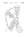
- FIG. 1 is a cross-sectional view of a brushless DC motor containing a termination board of the present invention
- FIG. 2 is an exploded perspective view of the termination board depicted in FIG. 1;
- FIG. 3 is a perspective view of the motor termination board depicted in FIGS. 1 and 2;
- FIG. 4 is a side view of the motor termination board depicted in FIG. 3;
- FIG. 5A is an enlarged top view of a first stamping contained in the motor termination board, where bridges between conductive paths existing prior to formation of the termination board are depicted;
- FIG. 5B is an enlarged top view of the first stamping shown in FIG. 5A, where certain bridges have been pierced and certain conductive paths have been disconnected during formation of the termination board to give the motor a delta configuration;
- FIG. 5C is an enlarged top view of the first stamping shown in FIG. 5A, where certain bridges have been pierced and certain conductive paths have been disconnected during formation of the termination board to give the motor a wye configuration;
- FIG. 6A is an enlarged top view of a second stamping contained in the motor termination board, where bridges between conductive paths existing prior to formation of the termination board are depicted;
- FIG. 6B is an enlarged top view of the second stamping shown in FIG. 6A, where certain bridges have been pierced and certain conductive paths have been disconnected during formation of the termination board to give the motor a delta configuration;
- FIG. 6C is an enlarged top view of the second stamping shown in FIG. 6A, where certain bridges have been pierced and certain conductive paths have been disconnected during formation of the termination board to give the motor a wye configuration.
- FIG. 1 depicts a brushless DC electric motor designated by the numeral 10.
- Motor 10 generally has a standard design which includes a stator 12 having coil windings 14 wrapped therein and a rotor 16 positioned concentrically inside stator 12 containing a plurality of field magnets 18. It will be understood that rotor 16 is mounted to a rotatable shaft 20 which extends through a center line axis 22 of motor 10. In this way, magnetic fields are induced between the rotor and stator as rotor 16 rotates. These magnetic fields (due to voltage excitation of coil windings 14) are then transformed into rotation and torque to shaft 20 so that work may be performed by an output end 21 thereof. In an electrical power steering system for a vehicle, for example, shaft output end 21 is utilized to drive a gear reduction attached to a steering column.
- a plurality of sensors 26, such as Hall effect sensors, are utilized to continuously sense the position of rotor 16 and send this rotor position information to an electronic control (not shown) connected to motor 10 to provide for appropriate switching therein.
- an annular holder 28 having a plurality of notches 29 properly positioned in an annular wall 31 thereof is preferably utilized to contain a body 25 of sensors 26 therein.
- Leads 27 of Hall effect sensors 26 are permitted to extend through holder 28 so they may be connected to first stamping 32, as described later herein. It is important that the Hall effect sensors 26 be properly positioned within motor 10 so that they align with the poles of field magnets 18, whereby they can provide accurate positioning information for rotor 16.
- Holder 28 will also be seen in FIG. 2 to contain a bearing insert 33 therein through which shaft 20 extends. It will be understood that a bearing (not shown) is mounted on shaft 20 so that the bearing's outer diameter engages bearing insert 33.
- a termination board identified generally by the numeral 30, is utilized to facilitate the interconnection of winding leads 24, sensors 26, an electronic control for motor 10, and a power source for motor 10.
- Termination board 30 may also be utilized to connect switching devices within the motor circuit to prevent an electrical short within coil windings 14 from acting as a brake to the turning of rotor 16, as will be discussed in more detail hereinafter. More specifically, as best seen in FIG. 2, termination board 30 includes a first stamping 32 having a plurality of conductive paths, a second stamping 34 having a plurality of conductive paths, and a termination board housing 36 for encapsulating the conductive paths of first and second stampings 32 and 34.
- first stamping 32 which preferably is made of half hard, pre-tin plated brass, has a plurality of connection points 38, 39 and 41 for receiving leads 27 from each sensor 26, as well as a plurality of control terminals 42 for connecting termination board 30 to an electronic control of motor 10.
- Control terminals 42 preferably will take the form of connector pins, which are formed by curling terminals 42.
- Connector pins 42 will then be positioned in two parallel rows 52 and 54 of four each, as best seen in FIGS. 2-4. This occurs by having specified bend points 53 in certain terminals 42A, 42B, 42C, and 42D to position them in a plane below first stamping 32 (see FIG. 5A).
- terminals 42E, 42F, 42G, and 42H of row 54 lie within the same plane as first stamping 32 and are substantially parallel to terminals 42A-D.
- terminals 42A-H may be designed to connect wire leads which can be extended to the electronic control or an intermediate connection device.
- First stamping 32 also includes a plurality of connection points 44 for connection to switching devices, as discussed later herein.
- a plurality of bridges 46 are shown in FIG. 5A as connecting adjacent conductive paths (e.g., conductive paths 48 and 50), whereby first stamping 32 may be maintained as a single piece for ease of handling. It will be understood that certain ones of bridges 46 will be removed during the process of manufacturing termination board 30, as seen in FIGS. 5B and 5C, as well as breaks in certain conductive paths (including a central annular conductive path 49 and an outer annular conductive path 51) depending on whether motor 10 is to have a delta or wye configuration respectively. In this way, dielectric isolation between the appropriate conductive paths of first stamping 32 is facilitated.
- Second stamping 34 which preferably is made of a half hard, pre-tin plated copper, is best shown in FIGS. 6A-C, where a plurality of connection points or terminals 58 are provided for receiving leads 24 of coil windings 14. It will be seen that each terminal 58 is formed by cutting a common end portion 57 (see FIG. 6A) to leave three T-shaped members 59, 61 and 63, with the separate ends thereof then being curled (as best seen in FIG. 2). Terminals 58 are preferably bent substantially 90° from the plane in which second stamping 34 lies in order to better position winding leads 24 and provide efficient spacing within motor 10.
- a plurality of power terminals 64A, 64B and 64C are included on second stamping 34 for connection to a power supply (not shown), preferably one which provides three phase power.
- Terminals 64A-C preferably are in the form of flat pins which lie in the same plane as second stamping 34, as seen in FIGS. 2-4, but may be designed to connect wire leads which can be extended to the power supply or an intermediate connection device.
- Second stamping 34 also includes connection points 60, 62 and 74 for connecting second stamping 34 with a switching device as described later herein.
- bridges 66 and 67 shown in FIG. 6A connect adjacent conductive paths and adjacent sets of terminals 58, respectively, and are utilized to enable second stamping 34 to be handled as a single piece during the manufacturing process.
- certain ones of bridges 66 will be removed during the process of manufacturing termination board 30, as seen in FIGS. 6B and 6C, along with breaks in certain conductive paths (including an inner annular conductive path 65). Additionally, larger bridges 67 positioned between adjacent sets of terminals 58 are removed.
- first and second stampings 32 and 34 have been configured with their respective conductive paths, connection points, and terminals so as to minimize the number of stampings required. This not only allows termination board 30 to be smaller in size and thus reduce the amount of space required in motor 10, but also saves cost in X terms of material needed and assembly time. However, if desired, more than two stampings may be utilized in conjunction with termination board 30 and still be within the scope of the present invention. For example, two separate stampings could be substituted for first stamping 32, whereby each row of control connector pins 42 could be associated with a separate stamping in order to eliminate the need for bend points 53 in terminals 42A-D.
- Termination board housing 36 which is preferably made of a high dielectric material (e.g., polyester (PET) (TP)), has a substantially planar main section 37 with a central opening 43 for shaft 20 to extend through and an outer perimeter configured to be properly positioned within motor 10. Additionally, termination board housing 36 preferably includes a first socket 56 positioned around control connector pins 42 for reception of a connection plug which connects motor 10 with the electronic control therefor, as well as a second socket 68 formed around power connector pins 64 so that a suitable plug may be received for connection with a power supply. Termination board housing 36 also may include a plurality of walls 70 adjacent terminals 58 which extend substantially 90° from a plane through termination board housing 36. Walls 70, which may assist in positioning switching devices 72, each include a pair of ribs 71 and 73 which extend between adjacent terminals 58 to prevent shorting of the winding leads 24 connected thereto.
- TP polyester
- relays for switching devices 72
- other switching devices such as transistors
- connection points 44 of first stamping 32 are connected by soldering or the like to the coil terminals of relays 72 and connection points 60, 62, and 74 of second stamping 34 connect motor winding leads 24 to the contact terminals of relays 72.
- a power connection is made to relays 72 by means of a connecting point 74 on second stamping 34, depending on whether motor 10 is connected in a delta or wye configuration.
- termination board 30 is able to provide all necessary interconnections between power connector pins or terminals 64, relays 72, Hall effect sensors 26, and control connector pins or terminals 42 in an integral package which minimizes space requirements within motor 10.
- this device for minimizing space enables relays 72 to be positioned within motor 10 without significantly increasing the overall size thereof.
- motor 10 includes a motor housing 76, which is located around stator 12 and holds stator 12, termination board 30, and holder 28 together with a flange 80.
- a termination cover 78 is attached to motor housing 76 and is positioned on the opposite side of termination board 30. It will be understood that power connector pins 64 and control connector pins 42, as well as sockets 68 and 56 surrounding such respective pins, will extend outwardly of housing 76 and termination cover 78.
- first and second stampings 32 and 34 are positioned in a mold where they are held by pairs of opposing pins at the holes in connection points 44 and connection points 60, 62 and 74, respectively. Pairs of opposing pins are also located at locations where bridges 46 and 66 are pierced to detach individual conductive paths in first and second stampings 32 and 34. Thereafter, the high dielectric material used for termination board housing 36 is injected into the mold to encapsulate the conductive paths of first and second stamping 32 and 34, as well as form sockets 56 and 68 around control connector pins 42 and power connector pins 64.
- walls 70 with ribs 71 and 73 are also formed to maintain the positioning of winding terminals 58.
- termination board 30 is removed from the mold, bridges 67 are removed from second stamping 34, and terminals 58 are bent into position.
- the construction of termination board 30 and the respective materials utilized for first stamping 32, second stamping 34, and termination board housing 36 enable it to handle currents in excess of 25 Amperes, which is much greater than that handled by current printed circuit board technology.
- annular wall 31 of holder 28 may be incorporated into the bottom surface of termination board housing 36, for example.
Landscapes
- Engineering & Computer Science (AREA)
- Power Engineering (AREA)
- Microelectronics & Electronic Packaging (AREA)
- Brushless Motors (AREA)
- Motor Or Generator Frames (AREA)
- Lens Barrels (AREA)
- Iron Core Of Rotating Electric Machines (AREA)
- Compressor (AREA)
- Motor Or Generator Cooling System (AREA)
- Insulation, Fastening Of Motor, Generator Windings (AREA)
Abstract
Description
Claims (21)
Priority Applications (11)
| Application Number | Priority Date | Filing Date | Title |
|---|---|---|---|
| US08/552,344 US5770902A (en) | 1995-11-02 | 1995-11-02 | Motor termination board |
| CA002236212A CA2236212C (en) | 1995-11-02 | 1996-09-25 | Motor termination board |
| PCT/US1996/015333 WO1997016883A1 (en) | 1995-11-02 | 1996-09-25 | Motor termination board |
| BR9611361A BR9611361A (en) | 1995-11-02 | 1996-09-25 | Motor termination panel and brushless DC motor |
| CN96198098A CN1068151C (en) | 1995-11-02 | 1996-09-25 | Motor Termination Board |
| AU71181/96A AU700034B2 (en) | 1995-11-02 | 1996-09-25 | Motor termination board |
| AT96932332T ATE255293T1 (en) | 1995-11-02 | 1996-09-25 | ENGINE CONNECTION PLATE |
| EP96932332A EP0872008B1 (en) | 1995-11-02 | 1996-09-25 | Motor termination board |
| DE69630893T DE69630893T2 (en) | 1995-11-02 | 1996-09-25 | MOTOR CONNECTION PLATE |
| KR1019980703234A KR100292933B1 (en) | 1995-11-02 | 1996-09-25 | Motor termination board |
| MX9803472A MX9803472A (en) | 1995-11-02 | 1998-04-30 | Motor termination board. |
Applications Claiming Priority (1)
| Application Number | Priority Date | Filing Date | Title |
|---|---|---|---|
| US08/552,344 US5770902A (en) | 1995-11-02 | 1995-11-02 | Motor termination board |
Publications (1)
| Publication Number | Publication Date |
|---|---|
| US5770902A true US5770902A (en) | 1998-06-23 |
Family
ID=24204941
Family Applications (1)
| Application Number | Title | Priority Date | Filing Date |
|---|---|---|---|
| US08/552,344 Expired - Fee Related US5770902A (en) | 1995-11-02 | 1995-11-02 | Motor termination board |
Country Status (10)
| Country | Link |
|---|---|
| US (1) | US5770902A (en) |
| EP (1) | EP0872008B1 (en) |
| KR (1) | KR100292933B1 (en) |
| CN (1) | CN1068151C (en) |
| AT (1) | ATE255293T1 (en) |
| AU (1) | AU700034B2 (en) |
| BR (1) | BR9611361A (en) |
| DE (1) | DE69630893T2 (en) |
| MX (1) | MX9803472A (en) |
| WO (1) | WO1997016883A1 (en) |
Cited By (84)
| Publication number | Priority date | Publication date | Assignee | Title |
|---|---|---|---|---|
| WO2000001054A1 (en) * | 1998-06-30 | 2000-01-06 | General Electric Company | Motor endshield assembly for an electronically commutated motor |
| US6078117A (en) * | 1997-08-27 | 2000-06-20 | Nartron Corporation | End cap assembly and electrical motor utilizing same |
| WO2000057539A1 (en) * | 1999-03-25 | 2000-09-28 | General Electric Company | Electric motor with ice out protection |
| US6232687B1 (en) | 1999-03-25 | 2001-05-15 | General Electric Company | Electric motor having snap connection assembly |
| FR2802026A1 (en) * | 1999-12-01 | 2001-06-08 | Milwaukee Electric Tool Corp | ASSEMBLY METHOD AND ASSEMBLY FORMING ELECTRICAL CONNECTOR FOR A POWER TOOL |
| US6252320B1 (en) * | 1999-05-24 | 2001-06-26 | Unit Parts Company | Alternator system |
| US6268669B1 (en) * | 1997-10-01 | 2001-07-31 | Kayaba Kogyo Kabushiki Kaisha | Electric motor for power steering device |
| US6271609B1 (en) * | 1999-03-25 | 2001-08-07 | General Electric Company | Programmable electric motor and method of assembly |
| WO2001057990A1 (en) * | 2000-02-01 | 2001-08-09 | Robert Bosch Gmbh | Stamped grid with an integrated hall sensor for rotational speed pick-off |
| US6317332B1 (en) * | 1998-02-05 | 2001-11-13 | Robert Bosch Gmbh | Electronic module for an electric motor operated drive unit |
| US20020175574A1 (en) * | 2001-05-25 | 2002-11-28 | Mitsubishi Denki Kabushiki Kaisha | Motor for use with motorized power steering apparatus |
| WO2003001647A1 (en) * | 2001-06-22 | 2003-01-03 | Minebea Co., Ltd. | Housing cover for an electric motor, in particular for an electronically-commutated dc motor |
| US20030076001A1 (en) * | 2001-02-28 | 2003-04-24 | Youichi Fujita | Exciting substrate of rotary electric machinery |
| US20030127921A1 (en) * | 2002-01-08 | 2003-07-10 | Mitsubishi Denki Kabushiki Kaisha | Electric power steering apparatus |
| WO2003052903A3 (en) * | 2001-12-14 | 2003-09-04 | Conti Temic Microelectronic | Electric drive unit comprising an integrated control module |
| WO2003026104A3 (en) * | 2001-09-14 | 2003-10-30 | Brose Fahrzeugteile | Drive unit comprising an electric motor for adjusting devices in motor vehicles |
| US6661140B2 (en) * | 2001-12-11 | 2003-12-09 | Black & Decker Inc. | Brushless motor having housing enabling alignment of stator and sensor |
| US20030230945A1 (en) * | 2002-06-13 | 2003-12-18 | Masayuki Okubo | Brushless motor |
| US6667564B1 (en) * | 2002-08-22 | 2003-12-23 | Buehler Motor, Inc. | Mechanically-commutated DC motor |
| US20040007935A1 (en) * | 2002-07-11 | 2004-01-15 | Kiyoshi Kimura | Rotary electric machine |
| US20040017120A1 (en) * | 2002-07-24 | 2004-01-29 | Lyle David M. | Three phase electric motor terminal box mounted connection board |
| US20040027014A1 (en) * | 2001-04-20 | 2004-02-12 | Thomas Weigold | Electronically commutated direct current motor |
| FR2843497A1 (en) * | 2002-08-07 | 2004-02-13 | Denso Corp | ELECTRIC POWER CONTROL UNIT CIRCUIT STRUCTURE |
| US6747380B2 (en) * | 2000-02-01 | 2004-06-08 | Bühler Motor GmbH | Direct winding wire to external conductor connected multi-phase motor |
| US20040115961A1 (en) * | 2002-10-21 | 2004-06-17 | Sabine Burhenne | Connecting element for an electric motor |
| US20040124726A1 (en) * | 2002-11-11 | 2004-07-01 | Helmut Hans | Device for connecting electronic components for driving an electric motor |
| EP1441433A1 (en) * | 2003-01-24 | 2004-07-28 | INARCA S.p.A. | Connection assembly, particular for the stator windings of an electric motor |
| US20040206194A1 (en) * | 2001-06-25 | 2004-10-21 | Cesar Proano | Electronic control device for window openers and other motor-activated mechanisms |
| US20050027198A1 (en) * | 2003-07-31 | 2005-02-03 | Couvillon Lucien Alfred | Ultrasonic imaging catheter |
| US6873072B2 (en) * | 2001-06-22 | 2005-03-29 | Minebea Co., Ltd. | Relay support device for an electric motor, in particular for an electrically commutated DC motor |
| US20050082918A1 (en) * | 2002-04-10 | 2005-04-21 | Luk Lamellen Und Kupplungsbau Beteiligungs Kg | Drive arrangement with a fixed bearing |
| EP1372241A3 (en) * | 2002-06-10 | 2005-08-10 | Delphi Technologies, Inc. | Multi-pole electromagnetic motor apparatus and method of assembling |
| US20050285461A1 (en) * | 2004-06-29 | 2005-12-29 | Shimano Inc. | Bicycle electrical generator hub |
| US6982509B2 (en) | 2003-05-16 | 2006-01-03 | Alto U.S. Inc. | Drip cover for floor polishing machine |
| US20060006749A1 (en) * | 2004-07-06 | 2006-01-12 | Hitachi, Ltd. | Controller for electric power steering and electric power steering system |
| US20060063403A1 (en) * | 2004-09-21 | 2006-03-23 | Nidec Corporation | Motor |
| US20060138883A1 (en) * | 2004-12-28 | 2006-06-29 | Hitachi, Ltd. | Motor for electric power steering and method for manufacturing the same |
| GB2390488B (en) * | 2002-02-04 | 2006-11-08 | Milwaukee Electric Tool Corp | Electrical devices including a switched reluctance motor |
| US20070051555A1 (en) * | 2005-08-24 | 2007-03-08 | Trw Automotive U.S. Llc | Sensor mounting for power assisted steering system |
| US20070107975A1 (en) * | 2003-11-18 | 2007-05-17 | Jtekt Corporation | Electric power steering device |
| US20070205678A1 (en) * | 2006-03-06 | 2007-09-06 | Mitsubishi Electric Corporation | Rotary electric machine |
| US20070236096A1 (en) * | 2006-04-06 | 2007-10-11 | Stefan Dorner | Carbon brush holder device |
| US20080036316A1 (en) * | 2006-08-08 | 2008-02-14 | Nidec Sankyo Corporation | Geared motor |
| US20080073987A1 (en) * | 2006-09-26 | 2008-03-27 | Nidec Corporation | Resolver and brushless motor |
| US20080093941A1 (en) * | 2006-10-24 | 2008-04-24 | Inarca S.P.A. | Assembly for connecting the electrical stator windings of an electric motor |
| US20080150377A1 (en) * | 2006-12-25 | 2008-06-26 | Mitsubishi Cable Industries, Ltd. | Insulating motor housing |
| US20080197726A1 (en) * | 2005-05-31 | 2008-08-21 | Valeo Equipements Electriques Moteur | Assembly of Electronic Components for Electrical Rotating Machine |
| WO2008122387A2 (en) | 2007-04-10 | 2008-10-16 | Sew-Eurodrive Gmbh & Co. Kg | Electric motor and fixing device for a printed circuit board |
| US20090251018A1 (en) * | 2008-04-07 | 2009-10-08 | Aisin Aw Co., Ltd. | Drive device |
| US20100102659A1 (en) * | 2008-10-24 | 2010-04-29 | Minebea Co., Ltd. | Motor for driving color wheel |
| US20100133935A1 (en) * | 2007-05-25 | 2010-06-03 | Hiroyuki Kinugawa | Brushless motor |
| US20110006626A1 (en) * | 2008-06-23 | 2011-01-13 | Hiroyuki Kinugawa | Insulating housing for motor terminal |
| US20110057524A1 (en) * | 2007-11-19 | 2011-03-10 | Sonceboz Automotive Sa | Electrical connector assembly for a brushless motor |
| US20120025643A1 (en) * | 2009-03-25 | 2012-02-02 | Mitsuba Corporation | Motor with speed reduction mechanism |
| US20130099610A1 (en) * | 2011-10-19 | 2013-04-25 | Denso Corporation | Driving apparatus |
| US20130154411A1 (en) * | 2011-12-16 | 2013-06-20 | Continental Automotive Systems, Inc. | Electromagnetic compatibility printed circuit board |
| WO2013154941A2 (en) | 2012-04-13 | 2013-10-17 | Globe Motors, Inc. | Method of positioning a sensor within a motor assembly |
| US20130334917A1 (en) * | 2012-06-18 | 2013-12-19 | Sanyo Denki Co., Ltd. | Brushless motor |
| US20140021813A1 (en) * | 2006-03-16 | 2014-01-23 | ThysseKrupp Elevator AG | Elevator Drive |
| US20140319941A1 (en) * | 2011-05-03 | 2014-10-30 | Aldebaran Robotics | Printed circuit intended to ensure connection of an electric motor and electric motor comprising the printed circuit |
| JP2015006089A (en) * | 2013-06-21 | 2015-01-08 | 多摩川精機株式会社 | Connector fixing structure in motor case |
| US9180906B2 (en) | 2011-10-19 | 2015-11-10 | Denso Corporation | Driving apparatus |
| US20150333589A1 (en) * | 2012-12-18 | 2015-11-19 | Spal Automotive S.R.L. | Electrical machine |
| US9231503B2 (en) * | 2014-05-28 | 2016-01-05 | Google Inc. | Methods and apparatuses for selectively controlling motor power boards |
| JP2016103944A (en) * | 2014-11-28 | 2016-06-02 | 日本電産株式会社 | motor |
| JP2016103945A (en) * | 2014-11-28 | 2016-06-02 | 日本電産株式会社 | motor |
| US9450472B2 (en) | 2010-06-14 | 2016-09-20 | Black & Decker, Inc. | Rotor assembly for brushless motor for a power tool |
| US20160352182A1 (en) * | 2014-02-03 | 2016-12-01 | Schaeffler Technologies AG & Co. KG | Electric motor with retainer disc and method for assembling same |
| US9761397B1 (en) * | 2016-06-23 | 2017-09-12 | Te Connectivity Corporation | Electrical relay device |
| US9812918B2 (en) | 2012-09-26 | 2017-11-07 | Sonceboz Automotive Sa | Electrical connection assembly for brushless motor and system comprising such an assembly |
| US9831580B2 (en) | 2015-09-15 | 2017-11-28 | Ghsp, Inc. | Vehicle-mounted sensorless motor with edge-connected termination |
| US20180041098A1 (en) * | 2015-02-11 | 2018-02-08 | Trw Limited | An Electric Circuit For Use In An Electric Power Assisted Steering System |
| EP2584672A3 (en) * | 2011-10-19 | 2018-03-28 | Robert Bosch Gmbh | Housing part for an electrical machine |
| US20190001452A1 (en) * | 2017-07-03 | 2019-01-03 | Makita Corporation | Power tool |
| US10236742B2 (en) | 2014-11-25 | 2019-03-19 | Black & Decker Inc. | Brushless motor for a power tool |
| JP2019068710A (en) * | 2017-09-28 | 2019-04-25 | 日本電産株式会社 | motor |
| US10285286B2 (en) * | 2013-10-04 | 2019-05-07 | Mitsubishi Electric Corporation | Electronic control device and method of manufacturing same, and electric power steering control device |
| US10328566B2 (en) | 2015-10-14 | 2019-06-25 | Black & Decker Inc. | Brushless motor system for power tools |
| DE102018121358A1 (en) * | 2018-08-31 | 2020-03-05 | Valeo Siemens Eautomotive Germany Gmbh | Busbar connector for a connection between an electric motor and an inverter |
| WO2020148380A1 (en) * | 2019-01-18 | 2020-07-23 | Brose Fahrzeugteile SE & Co. Kommanditgesellschaft, Würzburg | Drive device for a cooling fan |
| US10910899B2 (en) * | 2016-05-11 | 2021-02-02 | Hitachi Automotive Systems, Ltd. | Rotary electric machine |
| EP3770429A4 (en) * | 2018-05-28 | 2022-01-05 | Zhejiang Sanhua Intelligent Controls CO., Ltd. | ELECTRIC OIL PUMP |
| US20220069666A1 (en) * | 2020-08-31 | 2022-03-03 | Mabuchi Motor Co., Ltd. | Brushless motor |
| US12301067B2 (en) | 2023-05-30 | 2025-05-13 | Mabuchi Motor Co., Ltd. | Brushless motor |
Families Citing this family (18)
| Publication number | Priority date | Publication date | Assignee | Title |
|---|---|---|---|---|
| FR2765043B1 (en) * | 1997-06-24 | 2001-02-16 | Rockwell Lvs | MOTOR GEAR ACTIVATION OF A MOTOR VEHICLE FUNCTIONAL |
| DE19746518A1 (en) * | 1997-10-22 | 1999-04-29 | Bosch Gmbh Robert | Insert module for an electric motor window |
| DE29808744U1 (en) * | 1998-05-14 | 1998-09-10 | Stoeber Antriebstech Gmbh & Co | Motor terminal box |
| US7032290B2 (en) | 2002-03-22 | 2006-04-25 | Asmo Co., Ltd. | Manufacturing method for brush holder |
| DE10315871A1 (en) * | 2003-04-08 | 2004-10-21 | Ina-Schaeffler Kg | Brushless DC motor (BLDC motor) |
| DE102005046759A1 (en) * | 2005-09-29 | 2007-04-05 | BSH Bosch und Siemens Hausgeräte GmbH | Connection plate may be L-shaped and consist of a receiver region with sensor in opening and having a depression for holding conductor plate |
| EP1870364A1 (en) | 2006-06-23 | 2007-12-26 | Benninger AG | Thread tightener and device and method for operating a creel |
| JP4941007B2 (en) * | 2007-03-01 | 2012-05-30 | 日本電産株式会社 | motor |
| DE102007041334A1 (en) * | 2007-08-31 | 2009-03-05 | Siemens Ag Österreich | Circuit board for brushless DC motors |
| DE112009000845B4 (en) * | 2008-06-13 | 2016-02-25 | Mitsubishi Electric Corp. | engine assembly |
| EP2164314B1 (en) * | 2008-09-16 | 2014-11-19 | Grundfos Management A/S | Clamp cabinet for electrically connecting to an electric motor |
| DE102010005776A1 (en) * | 2010-01-25 | 2011-07-28 | Brose Fahrzeugteile GmbH & Co. Kommanditgesellschaft, Hallstadt, 96103 | Electric motor i.e. permanently energized direct current electric motor, for use in motor vehicle, has current transferring element and electrical contact element electrically connected together by channel in material-fit manner |
| US10316852B2 (en) * | 2015-05-11 | 2019-06-11 | Hanon Systems | Air conditioner for vehicle |
| FR3043859B1 (en) * | 2015-11-13 | 2020-11-13 | Valeo Systemes Thermiques | ELECTRIC MOTOR POWER CONTROL MODULE |
| JP2017158223A (en) * | 2016-02-29 | 2017-09-07 | オムロンオートモーティブエレクトロニクス株式会社 | Electric motor control device |
| DE102017222999B4 (en) * | 2017-12-18 | 2021-10-21 | Robert Bosch Gmbh | Sensor device for a steering system of a vehicle |
| DE102018202222B4 (en) * | 2018-02-14 | 2023-12-14 | Robert Bosch Gmbh | Steering device with steering sensor unit |
| FR3104340A1 (en) * | 2019-12-10 | 2021-06-11 | Sonceboz Mechatronics Boncourt Sa | ELECTRIC MOTOR |
Citations (18)
| Publication number | Priority date | Publication date | Assignee | Title |
|---|---|---|---|---|
| US4661733A (en) * | 1985-04-03 | 1987-04-28 | Asgalium Sa | DC motor |
| US4689023A (en) * | 1985-08-27 | 1987-08-25 | The Superior Electric Company | Programmable electrical connector |
| US4724346A (en) * | 1985-09-23 | 1988-02-09 | Siemens Aktiengesellschaft | Permanent magnet-excited external rotor motor |
| US4806808A (en) * | 1986-09-12 | 1989-02-21 | Siemens Aktiengesellschaft | Printed circuit board for external rotor motor with recess for Hall transducers |
| US4845396A (en) * | 1986-08-19 | 1989-07-04 | Capsonic Group, Inc. | Motor brush holder assembly |
| US4916345A (en) * | 1988-09-02 | 1990-04-10 | Chrysler Motors Corporation | Flat stator winding for alternator starter |
| US4926075A (en) * | 1987-12-28 | 1990-05-15 | Makita Electric Works, Ltd. | Electric motor brush assembly adaptable to different stators |
| US4926540A (en) * | 1986-08-05 | 1990-05-22 | Brother Kogyo Kabushiki Kaisha | Process for producing an electric motor |
| US4952829A (en) * | 1987-08-22 | 1990-08-28 | Robert Bosch Gmbh | Rectifier arrangement |
| US4968912A (en) * | 1989-08-21 | 1990-11-06 | Sundstrand Corporation | Single piece punched and bent neutral lead |
| US4975607A (en) * | 1988-07-11 | 1990-12-04 | Kabushiki Kaisha Sankyo Seiki Seisakusho | Frequency generator with superimposed generation coil |
| US4978876A (en) * | 1988-03-31 | 1990-12-18 | Schunk Motorensysteme Gmbh | Cup-shaped support for an electromotor |
| US4992688A (en) * | 1987-09-16 | 1991-02-12 | Papst-Motoren Gmbh & Co. Kg | Printed circuit board with a metallic layer for supporting an electrical component |
| US5006765A (en) * | 1986-03-06 | 1991-04-09 | Papst-Motoren Gmbh & Co. Kg | DC motor with coreless coil installation |
| US5280210A (en) * | 1987-12-30 | 1994-01-18 | Kress-Elektric Gmbh & Co. Elektromotorenfabrik | Universal electric motor with a switch ring mounted adjacent the brushes |
| US5309053A (en) * | 1991-01-18 | 1994-05-03 | Swf Auto-Electric Gmbh | Conductor embedded in an injection molded component for the cover of an electric motor |
| US5509625A (en) * | 1993-12-21 | 1996-04-23 | United Technologies Corp. | Electrical brush-wear indicator |
| US5552654A (en) * | 1993-10-21 | 1996-09-03 | Mitsubishi Chemical Corporation | Electrostatic actuator |
Family Cites Families (6)
| Publication number | Priority date | Publication date | Assignee | Title |
|---|---|---|---|---|
| US552654A (en) * | 1896-01-07 | Magazine-camera | ||
| DE3021948A1 (en) * | 1980-06-12 | 1981-12-24 | Rau Swf Autozubehoer | ELECTRIC DRIVE UNIT, IN PARTICULAR FOR WINDOW WIPERS OF A MOTOR VEHICLE |
| JPH0796387B2 (en) * | 1986-03-31 | 1995-10-18 | 本田技研工業株式会社 | Electric power steering device |
| DE3805060A1 (en) * | 1988-02-18 | 1989-08-31 | Miele & Cie | Electric motor having a system carrier for accommodating components, conductor tracks and control and regulation modules (chips) |
| JP3414851B2 (en) * | 1994-07-13 | 2003-06-09 | 本田技研工業株式会社 | Electric steering device |
| EP0731551A1 (en) * | 1995-03-08 | 1996-09-11 | KSB Aktiengesellschaft | Electric motor |
-
1995
- 1995-11-02 US US08/552,344 patent/US5770902A/en not_active Expired - Fee Related
-
1996
- 1996-09-25 DE DE69630893T patent/DE69630893T2/en not_active Expired - Fee Related
- 1996-09-25 CN CN96198098A patent/CN1068151C/en not_active Expired - Fee Related
- 1996-09-25 KR KR1019980703234A patent/KR100292933B1/en not_active Expired - Fee Related
- 1996-09-25 AU AU71181/96A patent/AU700034B2/en not_active Ceased
- 1996-09-25 BR BR9611361A patent/BR9611361A/en not_active IP Right Cessation
- 1996-09-25 AT AT96932332T patent/ATE255293T1/en not_active IP Right Cessation
- 1996-09-25 WO PCT/US1996/015333 patent/WO1997016883A1/en not_active Ceased
- 1996-09-25 EP EP96932332A patent/EP0872008B1/en not_active Expired - Lifetime
-
1998
- 1998-04-30 MX MX9803472A patent/MX9803472A/en not_active IP Right Cessation
Patent Citations (18)
| Publication number | Priority date | Publication date | Assignee | Title |
|---|---|---|---|---|
| US4661733A (en) * | 1985-04-03 | 1987-04-28 | Asgalium Sa | DC motor |
| US4689023A (en) * | 1985-08-27 | 1987-08-25 | The Superior Electric Company | Programmable electrical connector |
| US4724346A (en) * | 1985-09-23 | 1988-02-09 | Siemens Aktiengesellschaft | Permanent magnet-excited external rotor motor |
| US5006765A (en) * | 1986-03-06 | 1991-04-09 | Papst-Motoren Gmbh & Co. Kg | DC motor with coreless coil installation |
| US4926540A (en) * | 1986-08-05 | 1990-05-22 | Brother Kogyo Kabushiki Kaisha | Process for producing an electric motor |
| US4845396A (en) * | 1986-08-19 | 1989-07-04 | Capsonic Group, Inc. | Motor brush holder assembly |
| US4806808A (en) * | 1986-09-12 | 1989-02-21 | Siemens Aktiengesellschaft | Printed circuit board for external rotor motor with recess for Hall transducers |
| US4952829A (en) * | 1987-08-22 | 1990-08-28 | Robert Bosch Gmbh | Rectifier arrangement |
| US4992688A (en) * | 1987-09-16 | 1991-02-12 | Papst-Motoren Gmbh & Co. Kg | Printed circuit board with a metallic layer for supporting an electrical component |
| US4926075A (en) * | 1987-12-28 | 1990-05-15 | Makita Electric Works, Ltd. | Electric motor brush assembly adaptable to different stators |
| US5280210A (en) * | 1987-12-30 | 1994-01-18 | Kress-Elektric Gmbh & Co. Elektromotorenfabrik | Universal electric motor with a switch ring mounted adjacent the brushes |
| US4978876A (en) * | 1988-03-31 | 1990-12-18 | Schunk Motorensysteme Gmbh | Cup-shaped support for an electromotor |
| US4975607A (en) * | 1988-07-11 | 1990-12-04 | Kabushiki Kaisha Sankyo Seiki Seisakusho | Frequency generator with superimposed generation coil |
| US4916345A (en) * | 1988-09-02 | 1990-04-10 | Chrysler Motors Corporation | Flat stator winding for alternator starter |
| US4968912A (en) * | 1989-08-21 | 1990-11-06 | Sundstrand Corporation | Single piece punched and bent neutral lead |
| US5309053A (en) * | 1991-01-18 | 1994-05-03 | Swf Auto-Electric Gmbh | Conductor embedded in an injection molded component for the cover of an electric motor |
| US5552654A (en) * | 1993-10-21 | 1996-09-03 | Mitsubishi Chemical Corporation | Electrostatic actuator |
| US5509625A (en) * | 1993-12-21 | 1996-04-23 | United Technologies Corp. | Electrical brush-wear indicator |
Cited By (132)
| Publication number | Priority date | Publication date | Assignee | Title |
|---|---|---|---|---|
| US6078117A (en) * | 1997-08-27 | 2000-06-20 | Nartron Corporation | End cap assembly and electrical motor utilizing same |
| US6268669B1 (en) * | 1997-10-01 | 2001-07-31 | Kayaba Kogyo Kabushiki Kaisha | Electric motor for power steering device |
| US6317332B1 (en) * | 1998-02-05 | 2001-11-13 | Robert Bosch Gmbh | Electronic module for an electric motor operated drive unit |
| WO2000001054A1 (en) * | 1998-06-30 | 2000-01-06 | General Electric Company | Motor endshield assembly for an electronically commutated motor |
| US6232687B1 (en) | 1999-03-25 | 2001-05-15 | General Electric Company | Electric motor having snap connection assembly |
| WO2000057539A1 (en) * | 1999-03-25 | 2000-09-28 | General Electric Company | Electric motor with ice out protection |
| US6271609B1 (en) * | 1999-03-25 | 2001-08-07 | General Electric Company | Programmable electric motor and method of assembly |
| US6252320B1 (en) * | 1999-05-24 | 2001-06-26 | Unit Parts Company | Alternator system |
| US6476527B2 (en) * | 1999-05-24 | 2002-11-05 | Unit Parts Company | Alternator system |
| FR2802026A1 (en) * | 1999-12-01 | 2001-06-08 | Milwaukee Electric Tool Corp | ASSEMBLY METHOD AND ASSEMBLY FORMING ELECTRICAL CONNECTOR FOR A POWER TOOL |
| US20040171299A1 (en) * | 1999-12-01 | 2004-09-02 | Milwaukee Electric Tool Corporation | Method for assembling and electrical connector assembly for a power tool |
| US6927512B2 (en) | 1999-12-01 | 2005-08-09 | Milwaukee Electric Tool Corporation | Method for assembling an electrical connector assembly for a power tool |
| US6701604B2 (en) * | 1999-12-01 | 2004-03-09 | Milwaukee Electric Tool Corporation | Method for assembling a power tool |
| WO2001057990A1 (en) * | 2000-02-01 | 2001-08-09 | Robert Bosch Gmbh | Stamped grid with an integrated hall sensor for rotational speed pick-off |
| US6747380B2 (en) * | 2000-02-01 | 2004-06-08 | Bühler Motor GmbH | Direct winding wire to external conductor connected multi-phase motor |
| US20030076001A1 (en) * | 2001-02-28 | 2003-04-24 | Youichi Fujita | Exciting substrate of rotary electric machinery |
| US20040027014A1 (en) * | 2001-04-20 | 2004-02-12 | Thomas Weigold | Electronically commutated direct current motor |
| US6750574B2 (en) * | 2001-05-25 | 2004-06-15 | Mitsubishi Denki Kabushiki Kaisha | Motor for use with motorized power steering apparatus |
| US20020175574A1 (en) * | 2001-05-25 | 2002-11-28 | Mitsubishi Denki Kabushiki Kaisha | Motor for use with motorized power steering apparatus |
| WO2003001647A1 (en) * | 2001-06-22 | 2003-01-03 | Minebea Co., Ltd. | Housing cover for an electric motor, in particular for an electronically-commutated dc motor |
| US6873072B2 (en) * | 2001-06-22 | 2005-03-29 | Minebea Co., Ltd. | Relay support device for an electric motor, in particular for an electrically commutated DC motor |
| US20040206194A1 (en) * | 2001-06-25 | 2004-10-21 | Cesar Proano | Electronic control device for window openers and other motor-activated mechanisms |
| US20050040718A1 (en) * | 2001-09-14 | 2005-02-24 | Helmut Sesselmann | Drive unit comprising an electric motor for adjusting devices in motor vehicles |
| WO2003026104A3 (en) * | 2001-09-14 | 2003-10-30 | Brose Fahrzeugteile | Drive unit comprising an electric motor for adjusting devices in motor vehicles |
| US7061150B2 (en) | 2001-09-14 | 2006-06-13 | Brose Fahrzeugteile Gmbh & Co Kg, Coburg | Drive unit comprising an electric motor for adjusting devices in motor vehicles |
| US6661140B2 (en) * | 2001-12-11 | 2003-12-09 | Black & Decker Inc. | Brushless motor having housing enabling alignment of stator and sensor |
| WO2003052903A3 (en) * | 2001-12-14 | 2003-09-04 | Conti Temic Microelectronic | Electric drive unit comprising an integrated control module |
| US6707185B2 (en) * | 2002-01-08 | 2004-03-16 | Mitsubishi Denki Kabushiki Kaisha | Electric power steering apparatus |
| US20030127921A1 (en) * | 2002-01-08 | 2003-07-10 | Mitsubishi Denki Kabushiki Kaisha | Electric power steering apparatus |
| US7521826B2 (en) | 2002-02-04 | 2009-04-21 | Milwaukee Electric Tool Corporation | Power tools with switched reluctance motor |
| GB2390488B (en) * | 2002-02-04 | 2006-11-08 | Milwaukee Electric Tool Corp | Electrical devices including a switched reluctance motor |
| US7061146B2 (en) * | 2002-04-10 | 2006-06-13 | Luk Lamellen Und Kupplungsbau Beteiligungs Kg | Drive arrangement with a fixed bearing |
| US20050082918A1 (en) * | 2002-04-10 | 2005-04-21 | Luk Lamellen Und Kupplungsbau Beteiligungs Kg | Drive arrangement with a fixed bearing |
| EP1372241A3 (en) * | 2002-06-10 | 2005-08-10 | Delphi Technologies, Inc. | Multi-pole electromagnetic motor apparatus and method of assembling |
| US20030230945A1 (en) * | 2002-06-13 | 2003-12-18 | Masayuki Okubo | Brushless motor |
| US7196443B2 (en) * | 2002-07-11 | 2007-03-27 | Denso Corporation | Rotary electric machine |
| US20040007935A1 (en) * | 2002-07-11 | 2004-01-15 | Kiyoshi Kimura | Rotary electric machine |
| US20040017120A1 (en) * | 2002-07-24 | 2004-01-29 | Lyle David M. | Three phase electric motor terminal box mounted connection board |
| US6856056B2 (en) * | 2002-07-24 | 2005-02-15 | Emerson Electric Co. | Three phase electric motor terminal box mounted connection board |
| FR2843497A1 (en) * | 2002-08-07 | 2004-02-13 | Denso Corp | ELECTRIC POWER CONTROL UNIT CIRCUIT STRUCTURE |
| US6667564B1 (en) * | 2002-08-22 | 2003-12-23 | Buehler Motor, Inc. | Mechanically-commutated DC motor |
| US20040115961A1 (en) * | 2002-10-21 | 2004-06-17 | Sabine Burhenne | Connecting element for an electric motor |
| US20040124726A1 (en) * | 2002-11-11 | 2004-07-01 | Helmut Hans | Device for connecting electronic components for driving an electric motor |
| EP1441433A1 (en) * | 2003-01-24 | 2004-07-28 | INARCA S.p.A. | Connection assembly, particular for the stator windings of an electric motor |
| US6982509B2 (en) | 2003-05-16 | 2006-01-03 | Alto U.S. Inc. | Drip cover for floor polishing machine |
| US20050027198A1 (en) * | 2003-07-31 | 2005-02-03 | Couvillon Lucien Alfred | Ultrasonic imaging catheter |
| US7475755B2 (en) * | 2003-11-18 | 2009-01-13 | Jtekt Corporation | Electric power steering device |
| US20070107975A1 (en) * | 2003-11-18 | 2007-05-17 | Jtekt Corporation | Electric power steering device |
| US7042123B2 (en) * | 2004-06-29 | 2006-05-09 | Shimano Inc. | Bicycle electrical generator hub |
| US20050285461A1 (en) * | 2004-06-29 | 2005-12-29 | Shimano Inc. | Bicycle electrical generator hub |
| US20060006749A1 (en) * | 2004-07-06 | 2006-01-12 | Hitachi, Ltd. | Controller for electric power steering and electric power steering system |
| US7312545B2 (en) * | 2004-07-06 | 2007-12-25 | Hitachi, Ltd. | Controller for electric power steering and electric power steering system |
| US20060063403A1 (en) * | 2004-09-21 | 2006-03-23 | Nidec Corporation | Motor |
| US7663274B2 (en) * | 2004-09-21 | 2010-02-16 | Nidec Corporation | Motor |
| US20100187924A1 (en) * | 2004-12-28 | 2010-07-29 | Hitachi, Ltd. | Motor for Electric Power Steering and Method for Manufacturing the Same |
| US20060138883A1 (en) * | 2004-12-28 | 2006-06-29 | Hitachi, Ltd. | Motor for electric power steering and method for manufacturing the same |
| US7723878B2 (en) * | 2004-12-28 | 2010-05-25 | Hitachi, Ltd. | Motor for electric power steering and method for manufacturing the same |
| US8018104B2 (en) | 2004-12-28 | 2011-09-13 | Hitachi, Ltd. | Motor for electric power steering and method for manufacturing the same |
| US7800264B2 (en) * | 2005-05-31 | 2010-09-21 | Valeo Equipements Electriques Moteur | Assembly of electronic components for electrical rotating machine |
| US20080197726A1 (en) * | 2005-05-31 | 2008-08-21 | Valeo Equipements Electriques Moteur | Assembly of Electronic Components for Electrical Rotating Machine |
| US20070051555A1 (en) * | 2005-08-24 | 2007-03-08 | Trw Automotive U.S. Llc | Sensor mounting for power assisted steering system |
| US7448466B2 (en) | 2005-08-24 | 2008-11-11 | Trw Automotive U.S. Llc | Sensor mounting for power assisted steering system |
| US20070205678A1 (en) * | 2006-03-06 | 2007-09-06 | Mitsubishi Electric Corporation | Rotary electric machine |
| US7579729B2 (en) * | 2006-03-06 | 2009-08-25 | Mitsubishi Electric Corporation | Rotary electric machine |
| US20140021813A1 (en) * | 2006-03-16 | 2014-01-23 | ThysseKrupp Elevator AG | Elevator Drive |
| US9206016B2 (en) * | 2006-03-16 | 2015-12-08 | Thyssenkrupp Elevator Ag | Elevator drive |
| US20070236096A1 (en) * | 2006-04-06 | 2007-10-11 | Stefan Dorner | Carbon brush holder device |
| US7573167B2 (en) * | 2006-08-08 | 2009-08-11 | Nidec Sankyo Corporation | Geared motor |
| US20080036316A1 (en) * | 2006-08-08 | 2008-02-14 | Nidec Sankyo Corporation | Geared motor |
| US7714470B2 (en) | 2006-09-26 | 2010-05-11 | Nidec Corporation | Resolver and brushless motor |
| US20080073987A1 (en) * | 2006-09-26 | 2008-03-27 | Nidec Corporation | Resolver and brushless motor |
| US20080093941A1 (en) * | 2006-10-24 | 2008-04-24 | Inarca S.P.A. | Assembly for connecting the electrical stator windings of an electric motor |
| US20080150377A1 (en) * | 2006-12-25 | 2008-06-26 | Mitsubishi Cable Industries, Ltd. | Insulating motor housing |
| US7579732B2 (en) * | 2006-12-25 | 2009-08-25 | Mitsubishi Cable Industries, Ltd. | Insulating motor housing |
| CN101227117B (en) * | 2006-12-25 | 2012-05-30 | 三菱电线工业株式会社 | Insulation case for motors |
| WO2008122387A2 (en) | 2007-04-10 | 2008-10-16 | Sew-Eurodrive Gmbh & Co. Kg | Electric motor and fixing device for a printed circuit board |
| DE102008016942B4 (en) | 2007-04-10 | 2022-01-27 | Sew-Eurodrive Gmbh & Co Kg | Electric motor, comprising a motor flange as a housing part and with a circuit board |
| WO2008122387A3 (en) * | 2007-04-10 | 2009-03-19 | Sew Eurodrive Gmbh & Co | Electric motor and fixing device for a printed circuit board |
| US8384257B2 (en) * | 2007-05-25 | 2013-02-26 | Mitsubishi Electric Corporation | Brushless motor |
| US20100133935A1 (en) * | 2007-05-25 | 2010-06-03 | Hiroyuki Kinugawa | Brushless motor |
| US20110057524A1 (en) * | 2007-11-19 | 2011-03-10 | Sonceboz Automotive Sa | Electrical connector assembly for a brushless motor |
| US8890380B2 (en) * | 2007-11-19 | 2014-11-18 | Sonceboz Automotive Sa | Electrical connector assembly for a brushless motor |
| US20090251018A1 (en) * | 2008-04-07 | 2009-10-08 | Aisin Aw Co., Ltd. | Drive device |
| US8344566B2 (en) * | 2008-04-07 | 2013-01-01 | Aisin Aw Co., Ltd. | Control device arrangement for hybrid vehicle electric motors |
| US8513843B2 (en) * | 2008-06-23 | 2013-08-20 | Mitsubishi Electric Corporation | Insulating housing for motor terminal |
| US20110006626A1 (en) * | 2008-06-23 | 2011-01-13 | Hiroyuki Kinugawa | Insulating housing for motor terminal |
| US20100102659A1 (en) * | 2008-10-24 | 2010-04-29 | Minebea Co., Ltd. | Motor for driving color wheel |
| US20120025643A1 (en) * | 2009-03-25 | 2012-02-02 | Mitsuba Corporation | Motor with speed reduction mechanism |
| US9450472B2 (en) | 2010-06-14 | 2016-09-20 | Black & Decker, Inc. | Rotor assembly for brushless motor for a power tool |
| US20140319941A1 (en) * | 2011-05-03 | 2014-10-30 | Aldebaran Robotics | Printed circuit intended to ensure connection of an electric motor and electric motor comprising the printed circuit |
| US8981607B2 (en) * | 2011-10-19 | 2015-03-17 | Denso Corporation | Driving apparatus |
| US20130099610A1 (en) * | 2011-10-19 | 2013-04-25 | Denso Corporation | Driving apparatus |
| EP2584672A3 (en) * | 2011-10-19 | 2018-03-28 | Robert Bosch Gmbh | Housing part for an electrical machine |
| US9180906B2 (en) | 2011-10-19 | 2015-11-10 | Denso Corporation | Driving apparatus |
| US9072183B2 (en) * | 2011-12-16 | 2015-06-30 | Continental Automotive Systems, Inc. | Electromagnetic compatibility printed circuit board |
| US20130154411A1 (en) * | 2011-12-16 | 2013-06-20 | Continental Automotive Systems, Inc. | Electromagnetic compatibility printed circuit board |
| US9190888B2 (en) | 2012-04-13 | 2015-11-17 | Globe Motors, Inc. | Method of positioning a sensor within a motor assembly |
| WO2013154941A2 (en) | 2012-04-13 | 2013-10-17 | Globe Motors, Inc. | Method of positioning a sensor within a motor assembly |
| US9634534B2 (en) * | 2012-06-18 | 2017-04-25 | Sanyo Denki Co., Ltd. | Brushless motor |
| US20130334917A1 (en) * | 2012-06-18 | 2013-12-19 | Sanyo Denki Co., Ltd. | Brushless motor |
| US9812918B2 (en) | 2012-09-26 | 2017-11-07 | Sonceboz Automotive Sa | Electrical connection assembly for brushless motor and system comprising such an assembly |
| US20150333589A1 (en) * | 2012-12-18 | 2015-11-19 | Spal Automotive S.R.L. | Electrical machine |
| US9997971B2 (en) * | 2012-12-18 | 2018-06-12 | Spal Automotive S.R.L. | Electrical machine |
| JP2015006089A (en) * | 2013-06-21 | 2015-01-08 | 多摩川精機株式会社 | Connector fixing structure in motor case |
| US10285286B2 (en) * | 2013-10-04 | 2019-05-07 | Mitsubishi Electric Corporation | Electronic control device and method of manufacturing same, and electric power steering control device |
| US10224781B2 (en) * | 2014-02-03 | 2019-03-05 | Schaeffler Technologies AG & Co. KG | Electric motor with retainer disc and method for assembling same |
| US20160352182A1 (en) * | 2014-02-03 | 2016-12-01 | Schaeffler Technologies AG & Co. KG | Electric motor with retainer disc and method for assembling same |
| US9231503B2 (en) * | 2014-05-28 | 2016-01-05 | Google Inc. | Methods and apparatuses for selectively controlling motor power boards |
| CN106464090A (en) * | 2014-05-28 | 2017-02-22 | X开发有限责任公司 | Method and apparatus for selectively controlling a motor switchboard |
| US10523081B2 (en) | 2014-11-25 | 2019-12-31 | Black & Decker Inc. | Brushless motor for a power tool |
| US10236742B2 (en) | 2014-11-25 | 2019-03-19 | Black & Decker Inc. | Brushless motor for a power tool |
| JP2016103944A (en) * | 2014-11-28 | 2016-06-02 | 日本電産株式会社 | motor |
| JP2016103945A (en) * | 2014-11-28 | 2016-06-02 | 日本電産株式会社 | motor |
| US10804772B2 (en) * | 2015-02-11 | 2020-10-13 | Trw Limited | Electric circuit for use in an electric power assisted steering system |
| US20180041098A1 (en) * | 2015-02-11 | 2018-02-08 | Trw Limited | An Electric Circuit For Use In An Electric Power Assisted Steering System |
| US9831580B2 (en) | 2015-09-15 | 2017-11-28 | Ghsp, Inc. | Vehicle-mounted sensorless motor with edge-connected termination |
| US10786894B2 (en) | 2015-10-14 | 2020-09-29 | Black & Decker Inc. | Brushless motor system for power tools |
| US10500708B2 (en) | 2015-10-14 | 2019-12-10 | Black & Decker Inc. | Power tool |
| US11951603B2 (en) | 2015-10-14 | 2024-04-09 | Black & Decker Inc. | Brushless motor system for power tools |
| US10328567B2 (en) | 2015-10-14 | 2019-06-25 | Black & Decker Inc. | Brushless motor system for power tools |
| US10328566B2 (en) | 2015-10-14 | 2019-06-25 | Black & Decker Inc. | Brushless motor system for power tools |
| US10910899B2 (en) * | 2016-05-11 | 2021-02-02 | Hitachi Automotive Systems, Ltd. | Rotary electric machine |
| US9761397B1 (en) * | 2016-06-23 | 2017-09-12 | Te Connectivity Corporation | Electrical relay device |
| US20190001452A1 (en) * | 2017-07-03 | 2019-01-03 | Makita Corporation | Power tool |
| JP2019068710A (en) * | 2017-09-28 | 2019-04-25 | 日本電産株式会社 | motor |
| EP3770429A4 (en) * | 2018-05-28 | 2022-01-05 | Zhejiang Sanhua Intelligent Controls CO., Ltd. | ELECTRIC OIL PUMP |
| US11746766B2 (en) | 2018-05-28 | 2023-09-05 | Zhejiang Sanhua Intelligent Controls Co., Ltd | Electric oil pump |
| DE102018121358A1 (en) * | 2018-08-31 | 2020-03-05 | Valeo Siemens Eautomotive Germany Gmbh | Busbar connector for a connection between an electric motor and an inverter |
| WO2020148380A1 (en) * | 2019-01-18 | 2020-07-23 | Brose Fahrzeugteile SE & Co. Kommanditgesellschaft, Würzburg | Drive device for a cooling fan |
| US20220069666A1 (en) * | 2020-08-31 | 2022-03-03 | Mabuchi Motor Co., Ltd. | Brushless motor |
| US11715991B2 (en) * | 2020-08-31 | 2023-08-01 | Mabuchi Motor Co., Ltd. | Brushless motor |
| US12301067B2 (en) | 2023-05-30 | 2025-05-13 | Mabuchi Motor Co., Ltd. | Brushless motor |
Also Published As
| Publication number | Publication date |
|---|---|
| KR100292933B1 (en) | 2001-06-15 |
| CN1201564A (en) | 1998-12-09 |
| EP0872008A1 (en) | 1998-10-21 |
| CN1068151C (en) | 2001-07-04 |
| DE69630893D1 (en) | 2004-01-08 |
| ATE255293T1 (en) | 2003-12-15 |
| WO1997016883A1 (en) | 1997-05-09 |
| BR9611361A (en) | 1999-07-13 |
| AU700034B2 (en) | 1998-12-17 |
| MX9803472A (en) | 1998-09-30 |
| EP0872008A4 (en) | 1999-02-03 |
| KR19990067266A (en) | 1999-08-16 |
| AU7118196A (en) | 1997-05-22 |
| EP0872008B1 (en) | 2003-11-26 |
| DE69630893T2 (en) | 2004-08-26 |
Similar Documents
| Publication | Publication Date | Title |
|---|---|---|
| US5770902A (en) | Motor termination board | |
| US7514829B2 (en) | Busbar unit for an electric motor | |
| US7373711B2 (en) | Motor armature manufacturing method | |
| US6177741B1 (en) | Electric-motor wiring system | |
| US8089183B2 (en) | Lead frame connector | |
| JPWO2006109714A1 (en) | Motor equipment | |
| US11715991B2 (en) | Brushless motor | |
| JPH06233483A (en) | Connection structure of coil winding in stator | |
| KR102327471B1 (en) | Connection devices and electric motors | |
| JP2008148497A (en) | Bus bar structure, bus bar structure, and electric motor | |
| US20220224191A1 (en) | Electric motor with injection moulded stator | |
| DE102022210405A1 (en) | ENGINE | |
| US7102265B2 (en) | Four-pole synchronous motor | |
| US11909287B2 (en) | Insulator and motor comprising same | |
| DE102022210362A1 (en) | engine | |
| JP2006115681A (en) | Electric motor | |
| JP2883409B2 (en) | Small electric motor | |
| US4469967A (en) | Electric motor coil-retaining means | |
| CA2236212C (en) | Motor termination board | |
| US20220224209A1 (en) | Electric motor with injection moulded stator | |
| DE102022210360A1 (en) | engine | |
| JP3902219B1 (en) | Centralized power distribution parts | |
| CN211018504U (en) | Axial flow motor | |
| JP4913538B2 (en) | Centralized power distribution parts | |
| CN109301947B (en) | Stator and motor having the same |
Legal Events
| Date | Code | Title | Description |
|---|---|---|---|
| AS | Assignment |
Owner name: GLOBE MOTORS, OHIO Free format text: ASSIGNMENT OF ASSIGNORS INTEREST;ASSIGNORS:BATTEN, L. JAY;QUEARY, DENNIS L.;REEL/FRAME:007794/0595 Effective date: 19951102 |
|
| CC | Certificate of correction | ||
| FPAY | Fee payment |
Year of fee payment: 4 |
|
| AS | Assignment |
Owner name: GLOBE MOTORS, INC., OHIO Free format text: CHANGE OF NAME;ASSIGNOR:LABINAL COMPONENTS & SYSTEMS, INC.;REEL/FRAME:012973/0573 Effective date: 20000609 |
|
| FEPP | Fee payment procedure |
Free format text: PAYOR NUMBER ASSIGNED (ORIGINAL EVENT CODE: ASPN); ENTITY STATUS OF PATENT OWNER: LARGE ENTITY Free format text: PAYER NUMBER DE-ASSIGNED (ORIGINAL EVENT CODE: RMPN); ENTITY STATUS OF PATENT OWNER: LARGE ENTITY |
|
| FPAY | Fee payment |
Year of fee payment: 8 |
|
| REMI | Maintenance fee reminder mailed | ||
| LAPS | Lapse for failure to pay maintenance fees | ||
| STCH | Information on status: patent discontinuation |
Free format text: PATENT EXPIRED DUE TO NONPAYMENT OF MAINTENANCE FEES UNDER 37 CFR 1.362 |
|
| FP | Lapsed due to failure to pay maintenance fee |
Effective date: 20100623 |