US577004A - George l - Google Patents
George l Download PDFInfo
- Publication number
- US577004A US577004A US577004DA US577004A US 577004 A US577004 A US 577004A US 577004D A US577004D A US 577004DA US 577004 A US577004 A US 577004A
- Authority
- US
- United States
- Prior art keywords
- steam
- oil
- holder
- pipe
- lubricant
- Prior art date
- Legal status (The legal status is an assumption and is not a legal conclusion. Google has not performed a legal analysis and makes no representation as to the accuracy of the status listed.)
- Expired - Lifetime
Links
- 239000011521 glass Substances 0.000 description 9
- 239000000314 lubricant Substances 0.000 description 8
- 239000003921 oil Substances 0.000 description 8
- 238000005266 casting Methods 0.000 description 1
- 238000004140 cleaning Methods 0.000 description 1
- 230000005494 condensation Effects 0.000 description 1
- 238000009833 condensation Methods 0.000 description 1
- 238000010276 construction Methods 0.000 description 1
- 239000012530 fluid Substances 0.000 description 1
- 230000001105 regulatory effect Effects 0.000 description 1
- 239000003760 tallow Substances 0.000 description 1
- 239000002699 waste material Substances 0.000 description 1
Images
Classifications
-
- F—MECHANICAL ENGINEERING; LIGHTING; HEATING; WEAPONS; BLASTING
- F16—ENGINEERING ELEMENTS AND UNITS; GENERAL MEASURES FOR PRODUCING AND MAINTAINING EFFECTIVE FUNCTIONING OF MACHINES OR INSTALLATIONS; THERMAL INSULATION IN GENERAL
- F16N—LUBRICATING
- F16N7/00—Arrangements for supplying oil or unspecified lubricant from a stationary reservoir or the equivalent in or on the machine or member to be lubricated
- F16N7/30—Arrangements for supplying oil or unspecified lubricant from a stationary reservoir or the equivalent in or on the machine or member to be lubricated the oil being fed or carried along by another fluid
Definitions
- the object of this invention is to provide a lubricator that will feed any grade of a lubri; cant, such as oil or tallow, in the.
- I form a casting consisting of a cylinder I, capable of holding a quantity of lubricant, said cylinder having an opening at the top, tted with a plug 2, by means of which the said lubricant may be introduced into the holder I, and also an opening 3 and threaded plug-'l at the base for the purpose of cleaning and draining the device.
- a jacketleaving an intermediate steam-space 5 which is connected by small pipes or tubes G 8 to the steam-pipe 2', leading to the steam-cylinder of the engine, by means of which a constant supply of live Serial'No. 584,591. (No model.)
- This pipe 8 leading from the steam-pipe 22, is fitted with a valve or cock 9 and extends downward and attached to the base of the indicator-glass tube 10, with an intermediate condensing-reservoir 13.
- This reservoir 13 serves as a means for taking up the surplus lubricant due to expansion, and having about one-fifth') the capacity of the holder l will gradually return the oil to the holder I after the same has become partly reduced.
- This indicator-glass lO is formed with a passage at the top and another 24: at the bottom and will show the level of oil and valve 27 to a jet I8, entering a glass tube 17,
- valves Arranged .intermediate of the glass tube 17 and the steam-pipe 22 are two valves, the one, 2l, to close entirely the passage to said steam- )ipe 22 and the other, 10, to close the assage l D to the glass tube 17.
- a small pipe 25 Arranged between these two valves 21 10 is a small pipe 25, leading direct to the holder 1, which, by the aid of a valve 2G, serves as a by-pass for the lubricant Ashould the tube I7 break on being repaired.
- the oil or other lubricant must attain the same heat as that ofv the live steam before it will assimilate with the steam and reach all points of the steam chest and cylinder, and that when the lubricant is fed into the cylinder at a temperature of perhaps Fahrenheit from thirty to sixty per cent.
- valves and cocks 7, 9, 19,21, and 27 opened which will admit live steam into the annular steam-space 5, to bring the lubricant to a high temperature, and steam to' the holder 1, through the pipe 6, and S through the 4condenser 13, and passage 24J
- This steam by' reason of condensation will accumulate in the bottomV of the holder 1 and gradually elevate the oil to the passage 14', and eventually to the injecting tube or nozzle 18.
- the quantity of oil passing through the nozzle 1'8 can be regulated by the valve 27 to the desired number of drops per minute, as secu through thc glass .tube 17.
- I claini develops'and holds in readiness allf 1.
- Thegcombination of the oil-receiver a discharge-pipe therefor the gage-glass connected to said oil-receiver, the condenser connected to, and arranged beneath said gageglass, whereby the oil in the oil-receiver is permitted toexpand, and means for supplying .steam to said condenser as and for the purpose set forth.
Landscapes
- Engineering & Computer Science (AREA)
- General Engineering & Computer Science (AREA)
- Chemical & Material Sciences (AREA)
- Combustion & Propulsion (AREA)
- Oil, Petroleum & Natural Gas (AREA)
- Mechanical Engineering (AREA)
- Lubrication Of Internal Combustion Engines (AREA)
Description
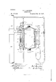
(No Model.)
` G. L. BRISBIN.
LUBRIGATOR.A y No. 577,004. l PatentedFebQl, 1897.
J V I WfTWSS/Qs WMS/Mme- WW ABM* i l l ,ox/t@ Numus ummm Lum... w nnnnnnnnn n c UNITED STATES PATENT OFFICE.'
GEORGE L. BRISBIN, OF MCKEESPORT, PENNSYLVANIA.
LUBRICATO R.
SPECIFICATION forming part of Letters Patent No. 577,004, dated February 16, 1897.
Application filed March 24,1896.
VTo @ZZ whom it `may concern:
Be it-known that I, GEORGE I.. BRIsBIN, a citizen of the United States, residing at Mc- Keesport, in the county of Allegheny and State of Pennsylvania, have invented certain make and use the same, reference being had cator for engines; and it consists in certain nomical manner and without waste.
to the accompanying drawing, and to the iigures of reference marked thereonwhich forms a part of this specification.
,My invention relates to an improved lubrivdetails of construction and combination of parts, as will be fully described hereinafter. In the accompanying drawing I have shown a side elevation of my improved lubricator,
partly shown in section and connected to the 'steam-pipe leading to the cylinder of' an cnl The object of this invention is to provide a lubricator that will feed any grade of a lubri; cant, such as oil or tallow, in the. coldest -weather and maintain a regular feed of as many drops per minute as desired in an eco- 'lhis I accomplish by means of a steam-jacket placed about the body' of the lubricator in a manner that the contents of the same may -bc expanded and vapori-Zed before entering the cylinder of the engine, together with a means -'for'taking upthe surplus lubricant caused` by expansion, and also to provide a by-pass for the fluid should the weak or frail glass4 hull break.
To construct a lubricaterin accordance with my invention, I form a casting consisting of a cylinder I, capable of holding a quantity of lubricant, said cylinder having an opening at the top, tted with a plug 2, by means of which the said lubricant may be introduced into the holder I, and also an opening 3 and threaded plug-'l at the base for the purpose of cleaning and draining the device. Surrounding this holder is a jacketleaving an intermediate steam-space 5, which is connected by small pipes or tubes G 8 to the steam-pipe 2', leading to the steam-cylinder of the engine, by means of which a constant supply of live Serial'No. 584,591. (No model.)
steam is kept circulating about the exterior walls of the holder l, and thereby keeping the lubricanteontained therein at a high temperature. This pipe 8, leading from the steam-pipe 22, is fitted with a valve or cock 9 and extends downward and attached to the base of the indicator-glass tube 10, with an intermediate condensing-reservoir 13. This reservoir 13 serves as a means for taking up the surplus lubricant due to expansion, and having about one-fifth') the capacity of the holder l will gradually return the oil to the holder I after the same has become partly reduced. This indicator-glass lO is formed with a passage at the top and another 24: at the bottom and will show the level of oil and valve 27 to a jet I8, entering a glass tube 17,
which, by means of a pipe 20, communicates with the interior of the steam-supply pipes 22.'
Arranged .intermediate of the glass tube 17 and the steam-pipe 22 are two valves, the one, 2l, to close entirely the passage to said steam- )ipe 22 and the other, 10, to close the assage l D to the glass tube 17. Arranged between these two valves 21 10 is a small pipe 25, leading direct to the holder 1, which, by the aid of a valve 2G, serves as a by-pass for the lubricant Ashould the tube I7 break on being repaired.-
It is understood by all skilled in the art that the oil or other lubricant must attain the same heat as that ofv the live steam before it will assimilate with the steam and reach all points of the steam chest and cylinder, and that when the lubricant is fed into the cylinder at a temperature of perhaps Fahrenheit from thirty to sixty per cent. of it is carried away by the exhaust-outlet before time was given to attain the same tempera-v ture as that of the steam; but with a lubrieator such as above described the proper degree of heat is attained' before leaving the holder l, and by the use of the steam-jacket the oil may be heated to such a degree that it will immediately vap'orizeupon coming in IOO lthe holder 1' through the opening at the top A and the plug screwed tightly in position, the
valves and cocks 7, 9, 19,21, and 27 opened, which will admit live steam into the annular steam-space 5, to bring the lubricant to a high temperature, and steam to' the holder 1, through the pipe 6, and S through the 4condenser 13, and passage 24J This steam by' reason of condensation will accumulate in the bottomV of the holder 1 and gradually elevate the oil to the passage 14', and eventually to the injecting tube or nozzle 18. The quantity of oil passing through the nozzle 1'8 can be regulated by the valve 27 to the desired number of drops per minute, as secu through thc glass .tube 17.
' vHaving thus described my in vent-ion, I claini develops'and holds in readiness allf 1. Thegcombination of the oil-receiver a discharge-pipe therefor the gage-glass connected to said oil-receiver, the condenser connected to, and arranged beneath said gageglass, whereby the oil in the oil-receiver is permitted toexpand, and means for supplying .steam to said condenser as and for the purpose set forth.-
2. The combination of the oil-receiver a discharge-pipe therefor the gage-glass connected to said oil-receiver, the condenser connected to, and arranged beneath said gageglass, and means 'for supplying steam thereto said oil-'receiver having a surrounding steamjacket, the sight-glass, and means for supply- Y ing steam to said steam-jacket, substantially as described.
In testimony whereof I ailix my signature in presence of two Witnesses.
` GEORGE L. BRISBIN.
itncsscsz f E. M. ARTHUR, Il. J. Lavis.
Publications (1)
| Publication Number | Publication Date |
|---|---|
| US577004A true US577004A (en) | 1897-02-16 |
Family
ID=2645695
Family Applications (1)
| Application Number | Title | Priority Date | Filing Date |
|---|---|---|---|
| US577004D Expired - Lifetime US577004A (en) | George l |
Country Status (1)
| Country | Link |
|---|---|
| US (1) | US577004A (en) |
-
0
- US US577004D patent/US577004A/en not_active Expired - Lifetime
Similar Documents
| Publication | Publication Date | Title |
|---|---|---|
| US577004A (en) | George l | |
| US640079A (en) | Lubricator. | |
| US384354A (en) | Thomas fitzpatrick | |
| US363682A (en) | Automatic lubricating apparatus | |
| US537584A (en) | Walter s | |
| US773545A (en) | Lubricator. | |
| US414785A (en) | Lubricator for steam-engines | |
| US484837A (en) | William h | |
| US138343A (en) | Improvement in lubricators for steam-engines | |
| US1183542A (en) | Sprinkling attachment for locomotives. | |
| US1350350A (en) | Steam production | |
| US313034A (en) | Lubricator | |
| US1749571A (en) | Apparatus for treating used lubricating oil | |
| US777765A (en) | Cylinder-lubricator. | |
| US671374A (en) | Automatic boiler-feeder. | |
| US929126A (en) | Heating system. | |
| US685600A (en) | Thermal storage apparatus for steam-boilers. | |
| US795753A (en) | Means for supplying water under constant pressure to freezing-plates. | |
| US485454A (en) | Lubricator | |
| US1395174A (en) | Lubricating device | |
| US218191A (en) | Improvement in lubricators | |
| US812578A (en) | Lubricator. | |
| US465679A (en) | Lubricator | |
| US305678A (en) | Automatic lubricator | |
| US1120699A (en) | Lubricator. |