US5765673A - Engaging apparatus - Google Patents
Engaging apparatus Download PDFInfo
- Publication number
- US5765673A US5765673A US08/705,906 US70590696A US5765673A US 5765673 A US5765673 A US 5765673A US 70590696 A US70590696 A US 70590696A US 5765673 A US5765673 A US 5765673A
- Authority
- US
- United States
- Prior art keywords
- friction plates
- spring member
- spline
- plates
- driven
- Prior art date
- Legal status (The legal status is an assumption and is not a legal conclusion. Google has not performed a legal analysis and makes no representation as to the accuracy of the status listed.)
- Expired - Lifetime
Links
- 238000005452 bending Methods 0.000 claims abstract description 7
- 239000013013 elastic material Substances 0.000 claims abstract description 4
- 230000005540 biological transmission Effects 0.000 description 30
- 230000008602 contraction Effects 0.000 description 4
- 230000010355 oscillation Effects 0.000 description 4
- 238000004512 die casting Methods 0.000 description 3
- 229910000639 Spring steel Inorganic materials 0.000 description 2
- 238000005266 casting Methods 0.000 description 2
- 230000000694 effects Effects 0.000 description 1
- 230000005484 gravity Effects 0.000 description 1
- 238000003780 insertion Methods 0.000 description 1
- 230000037431 insertion Effects 0.000 description 1
- 238000003754 machining Methods 0.000 description 1
- 239000000463 material Substances 0.000 description 1
- 238000000034 method Methods 0.000 description 1
- 230000002093 peripheral effect Effects 0.000 description 1
Images


Classifications
-
- F—MECHANICAL ENGINEERING; LIGHTING; HEATING; WEAPONS; BLASTING
- F16—ENGINEERING ELEMENTS AND UNITS; GENERAL MEASURES FOR PRODUCING AND MAINTAINING EFFECTIVE FUNCTIONING OF MACHINES OR INSTALLATIONS; THERMAL INSULATION IN GENERAL
- F16D—COUPLINGS FOR TRANSMITTING ROTATION; CLUTCHES; BRAKES
- F16D13/00—Friction clutches
- F16D13/22—Friction clutches with axially-movable clutching members
- F16D13/38—Friction clutches with axially-movable clutching members with flat clutching surfaces, e.g. discs
- F16D13/52—Clutches with multiple lamellae ; Clutches in which three or more axially moveable members are fixed alternately to the shafts to be coupled and are pressed from one side towards an axially-located member
-
- F—MECHANICAL ENGINEERING; LIGHTING; HEATING; WEAPONS; BLASTING
- F16—ENGINEERING ELEMENTS AND UNITS; GENERAL MEASURES FOR PRODUCING AND MAINTAINING EFFECTIVE FUNCTIONING OF MACHINES OR INSTALLATIONS; THERMAL INSULATION IN GENERAL
- F16D—COUPLINGS FOR TRANSMITTING ROTATION; CLUTCHES; BRAKES
- F16D25/00—Fluid-actuated clutches
- F16D25/06—Fluid-actuated clutches in which the fluid actuates a piston incorporated in, i.e. rotating with the clutch
- F16D25/062—Fluid-actuated clutches in which the fluid actuates a piston incorporated in, i.e. rotating with the clutch the clutch having friction surfaces
- F16D25/063—Fluid-actuated clutches in which the fluid actuates a piston incorporated in, i.e. rotating with the clutch the clutch having friction surfaces with clutch members exclusively moving axially
- F16D25/0635—Fluid-actuated clutches in which the fluid actuates a piston incorporated in, i.e. rotating with the clutch the clutch having friction surfaces with clutch members exclusively moving axially with flat friction surfaces, e.g. discs
- F16D25/0638—Fluid-actuated clutches in which the fluid actuates a piston incorporated in, i.e. rotating with the clutch the clutch having friction surfaces with clutch members exclusively moving axially with flat friction surfaces, e.g. discs with more than two discs, e.g. multiple lamellae
-
- F—MECHANICAL ENGINEERING; LIGHTING; HEATING; WEAPONS; BLASTING
- F16—ENGINEERING ELEMENTS AND UNITS; GENERAL MEASURES FOR PRODUCING AND MAINTAINING EFFECTIVE FUNCTIONING OF MACHINES OR INSTALLATIONS; THERMAL INSULATION IN GENERAL
- F16D—COUPLINGS FOR TRANSMITTING ROTATION; CLUTCHES; BRAKES
- F16D55/00—Brakes with substantially-radial braking surfaces pressed together in axial direction, e.g. disc brakes
- F16D55/24—Brakes with substantially-radial braking surfaces pressed together in axial direction, e.g. disc brakes with a plurality of axially-movable discs, lamellae, or pads, pressed from one side towards an axially-located member
- F16D55/26—Brakes with substantially-radial braking surfaces pressed together in axial direction, e.g. disc brakes with a plurality of axially-movable discs, lamellae, or pads, pressed from one side towards an axially-located member without self-tightening action
- F16D55/36—Brakes with a plurality of rotating discs all lying side by side
- F16D55/40—Brakes with a plurality of rotating discs all lying side by side actuated by a fluid-pressure device arranged in or one the brake
-
- F—MECHANICAL ENGINEERING; LIGHTING; HEATING; WEAPONS; BLASTING
- F16—ENGINEERING ELEMENTS AND UNITS; GENERAL MEASURES FOR PRODUCING AND MAINTAINING EFFECTIVE FUNCTIONING OF MACHINES OR INSTALLATIONS; THERMAL INSULATION IN GENERAL
- F16D—COUPLINGS FOR TRANSMITTING ROTATION; CLUTCHES; BRAKES
- F16D65/00—Parts or details
- F16D65/0006—Noise or vibration control
-
- F—MECHANICAL ENGINEERING; LIGHTING; HEATING; WEAPONS; BLASTING
- F16—ENGINEERING ELEMENTS AND UNITS; GENERAL MEASURES FOR PRODUCING AND MAINTAINING EFFECTIVE FUNCTIONING OF MACHINES OR INSTALLATIONS; THERMAL INSULATION IN GENERAL
- F16D—COUPLINGS FOR TRANSMITTING ROTATION; CLUTCHES; BRAKES
- F16D65/00—Parts or details
- F16D65/02—Braking members; Mounting thereof
- F16D65/04—Bands, shoes or pads; Pivots or supporting members therefor
- F16D65/092—Bands, shoes or pads; Pivots or supporting members therefor for axially-engaging brakes, e.g. disc brakes
- F16D65/095—Pivots or supporting members therefor
- F16D65/097—Resilient means interposed between pads and supporting members or other brake parts
-
- F—MECHANICAL ENGINEERING; LIGHTING; HEATING; WEAPONS; BLASTING
- F16—ENGINEERING ELEMENTS AND UNITS; GENERAL MEASURES FOR PRODUCING AND MAINTAINING EFFECTIVE FUNCTIONING OF MACHINES OR INSTALLATIONS; THERMAL INSULATION IN GENERAL
- F16D—COUPLINGS FOR TRANSMITTING ROTATION; CLUTCHES; BRAKES
- F16D55/00—Brakes with substantially-radial braking surfaces pressed together in axial direction, e.g. disc brakes
- F16D2055/0004—Parts or details of disc brakes
- F16D2055/0058—Fully lined, i.e. braking surface extending over the entire disc circumference
-
- F—MECHANICAL ENGINEERING; LIGHTING; HEATING; WEAPONS; BLASTING
- F16—ENGINEERING ELEMENTS AND UNITS; GENERAL MEASURES FOR PRODUCING AND MAINTAINING EFFECTIVE FUNCTIONING OF MACHINES OR INSTALLATIONS; THERMAL INSULATION IN GENERAL
- F16D—COUPLINGS FOR TRANSMITTING ROTATION; CLUTCHES; BRAKES
- F16D65/00—Parts or details
- F16D65/02—Braking members; Mounting thereof
- F16D2065/13—Parts or details of discs or drums
- F16D2065/134—Connection
- F16D2065/1392—Connection elements
- F16D2065/1396—Ancillary resilient elements, e.g. anti-rattle or retraction springs
Definitions
- the present invention relates to an engaging apparatus incorporated in an automatic transmission, and more particularly to a structure for preventing vibration of friction plates in a multiple-plate engaging apparatus.
- a multiple-plate type clutch or brake incorporated in an automatic transmission includes outer and inner support members that are rotatable relative to each other and have respective splines that are opposed to each other in the radial direction thereof, a plurality of outer friction plates engaging with the spline of the outer support member, a plurality of inner friction plates alternately superposed on the outer friction plates and engaging with the spline of the inner support member, and a hydraulic piston mechanism for compressing a stack of the outer and inner friction plates superposed on each other.
- the clutch or brake may further include a retaining member that is inhibited from moving in the axial direction relative to the spline of the corresponding support member, so as to receive compressive force applied to the friction plates.
- Japanese Patent Application Laid-open No. 2-46324 discloses a structure for preventing vibration of the friction plates when an engine brake is applied.
- a spring member is provided in the bottom of the spline, for biasing the friction plates in the radial direction, so as to eliminate clearances between the friction plates and the transmission case, thereby to reduce oscillation or rattling of the friction plates.
- the spring member restricts movements of the friction plates in the radial direction, and thus the friction plates may be off-centered with respect to the center axis of the case.
- the spline formed in the case during a die-casting process are not expected to assure high dimensional accuracy. Further, the spline is tapered to facilitate removal of a mold in the axial direction, thus inevitably leaving large clearances between the friction plates and the spline.
- the spline need to be formed with improved accuracy, by finishing side walls and bottom walls of the spline separately by cutting, for example.
- a plurality of friction plates are biased by the same spring member formed by bending a thin-plate spring material into a simple shape. Therefore, some of the friction plates may not be biased by the spring member. Further, the friction plates that abut on the case on the side remote from the spring member as viewed in the radial direction may disturb further deformation of the spring member. This may allow the other friction plates that do not abut on the case to oscillate or rattle in the circumferential direction.
- the assignee of the present application proposed in Japanese Patent Application No. 6-198038 a structure for preventing vibration of the friction plates in which a spring member is disposed between a side wall of the spline of the case and the friction plates, so as to eliminate clearances between the case and the friction plates in the circumferential direction.
- the spring member is located at an upper, left angular position as viewed from the side on which the inner friction plates are rotated clockwise.
- the spring member is adapted to prevent the vibration of the friction plates in the same direction in which the outer and inner friction plates are rotated relative to each other, thereby effectively avoiding the vibration of the friction plates on the side of the case.
- An engaging apparatus constructed according to the present invention includes outer support member and inner support member having first and second splines, respectively, that are opposed to each other in a radial direction thereof, which outer and inner support members are rotatable relative to each other, a plurality of outer friction plates engaging with the first spline of the outer support member, a plurality of inner friction plates alternately superposed on the outer friction plates and engaging with the second spline of the inner support member, and a hydraulic piston mechanism for compressing a stack of the outer and inner friction plates that are superposed on each other.
- a spring member is inserted between circumferentially opposed faces of a driven set of the outer and inner friction plates and the spline of a corresponding one of the outer and inner support members.
- the spring member is formed by bending an elastic material at an axially intermediate point thereof with a circumferential spacing left between both sides of a bent portion thereof.
- the spring member biases the friction plates in the circumferential direction, in particular, the friction plates are off-centered with respect to the center axis of the case by a smaller degree as compared with the case where the plates are biased in the radial direction.
- the friction plates and the spline of the case are in a uniform engaging condition over the entire circumference thereof even if large clearances are present between the friction plates and the walls of the spline.
- the spring member is formed by bending the elastic material in the axial direction, whereby the stroke of the spring can be set to a larger value than that obtained where the spring member is bent in the circumferential direction. Consequently, the friction plates can be stably positioned by the bias force which does not vary so much due to expansion and contraction of the spring member, and are thus prevented from losing the function of centering themselves due to an excessive bias force.
- the bent portion of the spring member is preferably located on the inner side of the spline toward which the spring member is inserted.
- This spring member is inserted through a large-width portion of the spline that is formed with a taper or draft, into the axially inner small-width side of the spline, such that the end portions of the spring member that is bent into a cuneate shape is located on the side of an opening of the spline. During the insertion, therefore, edges of the end portions of the spring member are not caught by the spline or other surrounding members.
- the bias force applied to the friction plates can be temporarily released by reducing a distance between the opposite end portions of the spring member that are located on the side of the opening of the spline.
- the bent portion of the spring member which is positioned on the inner side of the spline, does not interfere with other components located on the side of the opening of the spline.
- the bent portion of the spring member may be located on the inner side of the spline with respect to a support portion thereof that abuts on the driven set of the friction plates while the outer and inner friction plates are not in engagement with each other, as viewed in the direction in which the spring member is inserted into the spline.
- a distance between a point of biasing the friction plates and the bent portion is increased, whereby the friction plates can be stably biased by the spring member with a substantially constant bias force even if the point of biasing the fiction plates is displaced to a greater extent.
- the load burdens exerted on the bent portion due to expansion and contraction of the spring member in the circumferential direction.
- the spring member On the opposite sides of the bent portion of the spring member, there may be formed a relatively long side against which the driven set of the outer and inner friction plates are pressed, and a relatively short side having an end portion supported by a side wall of the spline.
- the long side and the short side form an angle larger than zero degree when the spring member is in a free state. Since the end portion of the short side of the spring member is supported along a line or at a point by the side wall of the spline of the support member, the spring member is able to control its posture by itself to conform to a variation in the circumferential length among the plurality of the friction plates, irrespective of the inclination of the side walls of the spline.
- the spring member carries out self-alignment, that is, controls its posture by itself, using the end portion of the short side as the center of the self-alignment while bringing the long side into contact with the side faces of the teeth of the friction plates. This eliminates clearances or room for allowing vibration of the friction plates in the circumferential direction.
- the end portion of the short side of the spring member is bent inwards so as to form a curved surface that protrudes outwards in the above arrangement, an edge of the end portion of the short side does not contact or slide on the surface of the support member defining the spline, and the curved surface that protrudes outwards prevents the wall surface of the spline from being worn off or unnecessarily caught by the spring member, assuring smooth contact and support of the spring member.
- the long side of the spring member may be formed with a distal end portion that is bent substantially squarely to protrude outwards, which distal end portion is located between the retaining plate and an opposed one of the friction plates.
- the protruding end porion of the long side of the spring member is received in a space corresponding to the thickness of the driving friction plate interposed between the retaining plate and the opposed driven friction plate, so as to position the spring member in the axial direction.
- the spring member is prevented from being deviated from its nominal position even if the spring member repeatedly expands and contracts in the circumferential direction, thus assuring high capability of preventing oscillations of the friction plates with high stability and reliability.
- One of the teeth of each of the friction plates which is located at the same angular position, may be formed with a smaller circumferential dimension than the other teeth, such that an axially continuous space for accommodating the spring member is formed between the short teeth of the friction plates and the corresponding spline of the support member.
- a difference in the width between the retaining plate and the short teeth of the friction plates restricts or inhibits axial movements of the spring member, and prevents the spring member from dropping off toward the retaining plate. This eliminates a need to provide the spring member with a structure for preventing dropping-off thereof, thus assuring increase freedom in designing and positioning the spring member.
- the above-indicated space for accommodating the spring member may be formed by setting back the wall of the spline of the support member, it is easier to shorten the teeth of the friction plates than machining the support member.
- the length of the short side of the spring member may be determined such that the short side terminates at a point that is approximately aligned with an axially middle portion of a support region of the long side on which the friction plates abut on while the outer and inner friction plates are not in engagement with each other.
- one and the other half of the friction plates are respectively located on one and the other of the axially opposite sides of the point at which the spring member is supported by the side wall of the spline of the support member, and the distance between the support point and one end of the stack of the friction plates is made substantially equal to that between the support point and the other end. Accordingly, all of the friction plates are biased by substantially the same force toward the side wall of the spline of the support member.
- At least one of the opposed faces of the friction plates and the spline is retracted or set back by an amount that is determined to be equal to or larger than a radius of a circle defining the bent portion of the spring member.
- the spring member is safely protected within the space and prevented from being damaged or permanently deformed, even if the friction plates are biased in such a direction that causes the spring member to be crushed or contracted.
- the spring member provides a sufficiently large stroke of expansion and contraction in the circumferential direction, thereby applying stable biasing force to all of the friction plates to effectively prevent the oscillation of the friction plates.
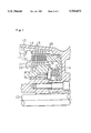
- FIG. 1 is a view showing in axial cross section an automatic transmission as one embodiment of the present invention
- FIG. 2 is a cross sectional view showing driven plates of the automatic transmission as viewed in the axial direction;
- FIG. 3 is a view showing a structure for preventing vibration of the driven plates.
- FIGS. 4A through 6B are views showing modified examples of a spring member.
- FIG. 4B is a cross sectional view along with a line A--A in FIG. 4A
- FIG. 5B is a cross sectional view along with a line B--B in FIG. 5A
- FIG. 6B is an end view in a direction C--C in FIG. 6A.
- FIG. 1 is a view showing in axial cross section a preferred embodiment of an engaging apparatus of the present invention, more particularly, an automatic transmission including a multiple-plate type brake.
- FIG. 2 is a cross sectional view showing one of driven plates of the multiple-plate type brake as viewed in the axial direction of the apparatus, and
- FIG. 3 is a view explaining a structure for preventing vibration of the driven plates.
- the multi-plate type brake disposed in the innermost part of a transmission case of the automatic transmission is provided with the structure for preventing vibration of friction plates.
- a spline 11 is formed inside a transmission case 10.
- the transmission case 10 including the spline 11 is produced by die casting as an integral body, such that the lines of the spline 11 is tapered in the axial direction, as shown in FIG. 3. While the inner circumferential surface of the case 10 defining the tops of the spline 11 is cut after the casting, the other walls of the spline 11 remain as they are when formed by casting.
- a snap ring 13 fitted into a snap ring groove 12 formed in the spline 11 serves to restrict axial movements of a retaining plate 14.
- the retaining plate 14 and driven plates (friction plates) 15 are formed at their outer peripheries with teeth that engage with the spline 11 so as to inhibit these plates 14, 15 from rotating relative to the transmission case 10 in the circumferential direction, while allowing the plates 14, 15 to move along the spline 11 in the axial direction.
- Drive plates 16 alternately superposed on the driven plates 15 are formed at their inner peripheries with teeth that engage with spline 21 of a rotary member 20, so as to allow the drive plates 16 to rotate as a unit with the rotary member 20 and also move along the spline 21 in the axial direction.
- the rotary member 20 is rotatable relative to the transmission case 10, about a center axis in common with an output shaft 22 of the automatic transmission.
- Other portions of a gear change mechanism of the transmission which are not shown in FIG. 1 are located on the left-hand side (in FIG. 1) of the rotary member 20.
- a mechanism for hydraulically driving the brake is located in the innermost portion of the transmission case 10. With an oil pressure applied to a cylinder chamber 18, a piston 19 that is normally biased inwards by a return spring 17 moves in the axial direction towards the driven plates 15 against the bias force of the return spring 17. The piston 19 cooperates with the retaining plate 14 to sandwich therebetween the driven plates 15 and drive plates 16 as they are superposed on each other, so as to generate frictional force between the driven plates 15 and the drive plates 16, thereby to inhibit the rotary member 20 from rotating.
- a spring member 25 is disposed between circumferentially opposed faces of the spline 11 and the driven plates 15.
- the spring member 25 has a structure as shown in FIG. 3, and located at an angular position as shown in FIG. 2. After the teeth of the driven plates 15 with the drive plates 16 alternately superposed thereon are inserted in the spline 11, and before the retaining plate 14 is set, the spring member 25 is inserted between the circumferentially opposed faces of the spline 11 and the corresponding teeth of the driven plates 15.
- the spring member 25 is provided between one of 28 side faces of the teeth of the driven plates 15 and one of the teeth of the spline 11 of the transmission case 10 which faces the above-indicated one side face in the circumferential direction.
- the drive plates 16 that are not shown in FIG. 2 are rotated in the direction as indicated by an arrow in FIG. 2.
- the drive plates 16 bring up left-side portions (in FIG. 2) of the driven plates 15 to cause collision between the circumferentially opposed faces of the plates 15 and the spline 11, and then drop the driven plates 15 as a result of gravity, thereby to cause collision between the opposite side faces of the teeth of the plates 15 and the corresponding faces of the spline 11.
- These movements of the driven plates 15 relative to the spline 11 are repeated with a result of noises.
- the driven plates 15 are biased in the circumferential direction such that their side faces remote from the spring member 25 are held in close contact with the corresponding face of the spline 11, thus leaving no tolerance or room for allowing vertical vibrations of the left-side portions of the driven plates.
- the spring member 25 restricts circumferential movements of the driven plates 15, and therefore leaves relatively small room for vibrations and reduces collision force of the driven plates 15, as compared with the case where the spring member 25 is not provided, thereby eliminating noises leaking outside the transmission case 10.
- the driven plates 15 are displaced by a certain angle in the direction of the arrow in FIG. 2, so that the side faces of the teeth of the plates 15 remote from the spring member 25 come into close contact with the corresponding side walls of the spline 11.
- the driven plates 15 are displaced by a certain angle in the direction opposite to that of the arrow in FIG. 2, so that the side faces of the teeth of the plates 15 on the side of the spring member 25 come into close contact with the corresponding side walls of the spline 11.
- the spring member 25 is sandwiched between the driven plates 15 and the corresponding spline 11, and thus compressed in the circumferential direction.
- the teeth 11H of the driven plates 15 located at the angular position at which the spring member 25 is provided has a width that is smaller by about 40% than that of the other teeth of the plates 15, to ensure a relatively large clearance in the circumferential direction.
- the spring member 25 does not undergo excessively large compressive deformation due to abutting contact between the other teeth of the driven plates 15 and the side walls of the spline 11.
- the driven plates 15 are further formed with relatively short teeth 11H at an angular position thereof that is symmetrical with the above-indicated teeth 11H abutting on the spring member 25, with respect to a symmetry axis of the plates 15. These teeth 11H formed in the symmetrical position ensure a space in which the spring member 25 is to be inserted when the driven plates 15 are mounted in the reverse direction, thus avoiding mistakes in mounting the driven plates 15.
- the spring member 25 is formed by bending a spring steel plate to assume the shape of the letter "J" turned on its side. Namely, the spring member 25 has a long side 25L supporting edges of the teeth of the plural driven plates 15, and a short side 25S having an end portion 27 that abuts on the inner surface of the transmission case 10 defining the relevant spline 11.
- the spring member 25 can control or adjust its posture by itself to conform to the circumferential length of the driven plates 15, so that the side faces of the teeth of the plates 15 remote from the spring member 25 are held in close contact with the corresponding side wall of the spline 11 with no clearance left in the circumferential direction. Further, the end portion 27 of the short side 25S abuts on the spline 11 (transmission case 10) at the center of support 29 where the driven plates 15 are evenly biased by the long side 25L. In this arrangement, approximately uniform bias force is applied to the driven plates 15 irrespective of inclination of the side wall of the spline 11 against which the plates 15 are biased.
- the long side 25L of the spring member 25 extends over a far larger length than a portion thereof supporting the driven plates 15, and a bent portion 28 at which the spring member 25 is bent when it is mounted is located on the axially inner side of the spline 11 remote from the portion supporting the driven plates 15. Accordingly, the open angle formed by the long side 25L and the short side 25S of the spring member 25 varies to a small extent when the spring member 25 expands and contracts in the circumferential direction. Thus, the open angle is kept larger than an angle of inclination of the walls of the spline 11 even when the spring member 25 is contracted, whereby all of the driven plates 15 are kept biased with substantially uniform bias force, with reduced stress applied to the bending portion 28 of the spring member 25.
- the bias force of the spring member 25 is set to a minimum level required for preventing vibration of the driven plates 15, so as not to disturb axial movements of the driven plates 15 and not to incline the driven plates 15 to such an extent that causes interference with the drive plates 16.
- a stopper 26 formed by erecting squarely an end portion of the long side 25L of the spring member 25 is located in a space (the size of which corresponds to the thickness of the drive plate 16) between the retaining plate 14 and the driven plate 15, so as to position the spring member 25 in the axial direction.
- the spring member 25 is mounted while being contracted to the circumferential length as shown in FIG. 3, from its free state PF (as indicated by dashed line in FIG. 3) before it is inserted into the spline 11. With the engine brake applied, the spring member 25 is deformed into its contracted state PC as indicated by dashed line in FIG. 3.
- the design freedom of the spring member 25 is increased, and the diameter of the arc formed by the bent portion 28 can be increased so as to reduce burdens exerted on the bent portion 28 upon expanding and contracting of the spring member 25.
- the stopper 26 With the spline 11 having a sufficiently large width, the stopper 26 abuts on the retaining plate 14, thereby preventing the spring member 25 from popping out toward the retaining plate 14.
- the end portion 27 of the short side 25S of the spring member 25 is bent inwards to thus form a curved surface on the outer side of the member 25. With this curved surface abutting on the side wall of the spline 11, the edge of the end portion 27 does not contact the wall surface of the spline 11, thus avoiding wear of the wall of the spline 11 due to repeated expansion and contraction of the spring member 25.
- the driven plates 15 are biased by the spring member 25 in the same direction in which these plates 15 are dragged along with the drive plates 16.
- the driven plates 15 and the spline 11 are kept in contact with each other, leaving no room for causing vibrations of the driven plates 15. Accordingly, no noise arises from the automatic transmission due to the vibration of the driven plates 15.
- the driven plates 15 With the spring member 25 biasing the driven plates 15 in the circumferential direction, the driven plates 15 are off-centered with respect to the center shaft by a smaller degree as compared with the case where these plates 15 are biased in the radial direction. Even if clearances between the driven plates 15 and the spline 11 in the radial direction vary to a great extent from portion to portion, the load applied to the teeth of the driven plates 15 received in the spline 11 is constant over the entire circumference of the plates 15, causing no damage of the driven plates 15 due to a variation in the load applied thereto.
- the driven plates 15 are free from vibrations and damages even if the plates 15 are loosely supported in the spline 11 that are formed merely by die-casting with poor accuracy, or if the driven plates 15 arranged in the axial direction have the same dimensions irrespective of the tapered walls of the spline 11.
- the spring member 25 having a simple shape can be manufactured at a low cost and easily mounted. Further, parts of a conventional automatic transmission, such as a transmission case, can be used without being modified except for the teeth 11H of the driven plates 15, so as to provide a quiet, highly reliable automatic transmission at a low cost.
- the present embodiment is directed to a structure for preventing vibration of friction plates in a multiple-plate brake of an automatic transmission
- the present invention is also applicable to a multiple-disk clutch of an automatic transmission in which a similar spring is mounted so as to eliminate rattling of the disks in the circumferential direction.
- FIGS. 4A and 4B show a modified example of spring member in which the spring member is formed by a wire rod
- FIGS. 5A and 5B show a modified example of spring member in which a bent portion of the spring member is received in a groove formed in the spline, so as to position the spring member in the axial direction
- FIGS. 6A and 6B show a modified example of spring member in which its distal portion supporting the driven plates branches off into a plurality of sections each supporting two of the driven plates.
- the wire rod made of a spring steel is bent or folded to form the spring member 31, which has a short side whose distal end portion is received in a hole 11A formed in the spline 11, so as to position the spring member 31.
- a circle with a sufficiently large diameter defines the bent portion of the spring member 32, while a spacing between the both sides of the bent portion is set to be relatively small.
- the spring member 32 thus formed can be mounted even when the driven plates 15 are opposed to the side wall of the spline with a small spacing left therebetween in the circumferential direction.
- the bent portion of the spring member 32 is received in the groove 11B formed in the spline 11 so that the spring member 32 is inhibited from moving in the axial direction.
- one side of the spring member 33 which does not contact the driven plates 15 is held in contact at its plane with the side wall of the spline 11.
- the spring member 33 does not have a function of controlling its posture by itself in accordance with the movements of the driven plates 15 like the above-described spring member 25.
- the other side of the spring member 33 contacting the driven plates 15 is divided along its length into three branches, each of which serves to bias two of the driven plates 15 respectively.
Abstract
Description
Claims (9)
Applications Claiming Priority (2)
| Application Number | Priority Date | Filing Date | Title |
|---|---|---|---|
| JP7-245457 | 1995-08-30 | ||
| JP24545795A JP3429399B2 (en) | 1995-08-30 | 1995-08-30 | Fastening device |
Publications (1)
| Publication Number | Publication Date |
|---|---|
| US5765673A true US5765673A (en) | 1998-06-16 |
Family
ID=17133953
Family Applications (1)
| Application Number | Title | Priority Date | Filing Date |
|---|---|---|---|
| US08/705,906 Expired - Lifetime US5765673A (en) | 1995-08-30 | 1996-08-28 | Engaging apparatus |
Country Status (3)
| Country | Link |
|---|---|
| US (1) | US5765673A (en) |
| JP (1) | JP3429399B2 (en) |
| DE (1) | DE19634973C2 (en) |
Cited By (17)
| Publication number | Priority date | Publication date | Assignee | Title |
|---|---|---|---|---|
| US5950991A (en) * | 1997-05-06 | 1999-09-14 | Eaton Corporation | Force transmitting apparatus |
| US6000514A (en) * | 1997-02-04 | 1999-12-14 | Jatco Corporation | Engaging device |
| KR20020050995A (en) * | 2000-12-22 | 2002-06-28 | 이계안 | structure for supporting clutch plate of multiple plate clutch |
| US6484853B1 (en) * | 2001-08-15 | 2002-11-26 | Raytech Composites, Inc. | Single sided friction assembly compensating for thermal distortions |
| EP1260726A2 (en) * | 2001-05-21 | 2002-11-27 | ZF Sachs AG | Multiple disc clutching device with coupled lamellae |
| US6508336B1 (en) * | 2000-02-04 | 2003-01-21 | Meritor Heavy Vehicle Systems, Llc | Reduced drag wet disc brake assembly |
| FR2835895A1 (en) * | 2002-02-11 | 2003-08-15 | Zf Sachs Ag | Automobile metal clutch installation has inner and outer strip supports coupled to output shaft by torque transmission part by strip support driving deformations and complementary torque transmission part deformations |
| US6695114B2 (en) * | 2001-02-19 | 2004-02-24 | Heidelberger Druckmaschinen Ag | Multi-disk clutch |
| US20050284723A1 (en) * | 2004-06-24 | 2005-12-29 | Raybestos Products Company | Alternative pack designs for multidisk clutches |
| US20070023250A1 (en) * | 2003-05-13 | 2007-02-01 | Mepham Shaun E | Clutches |
| US20070068745A1 (en) * | 2004-02-04 | 2007-03-29 | Knorr-Bremse Systeme Fuer Nutzfahrzeuge Gmbh | Adjusting device for pneumatically actuatable disk brakes and disk brakes |
| US20080296082A1 (en) * | 2007-05-31 | 2008-12-04 | Honda Motor Co., Ltd. | Twin clutch apparatus for power unit, power unit incorporating same, and vehicle incorporating same |
| US20130071173A1 (en) * | 2011-09-15 | 2013-03-21 | Johannes STEINDL | Pivot joint arrangement |
| DE10025533B4 (en) * | 1999-06-23 | 2014-07-24 | Zf Friedrichshafen Ag | Pressure plate assembly and friction clutch |
| US20160097443A1 (en) * | 2014-10-01 | 2016-04-07 | E-Aam Driveline Systems Ab | Driveline component having differential and park lock mechanism |
| US20220219489A1 (en) * | 2021-01-11 | 2022-07-14 | Honeywell International Inc. | Wheel and brake assembly with mechanical stop |
| US20220235849A1 (en) * | 2021-01-28 | 2022-07-28 | Mazda Motor Corporation | Automatic transmission |
Families Citing this family (1)
| Publication number | Priority date | Publication date | Assignee | Title |
|---|---|---|---|---|
| DE10205768A1 (en) * | 2002-02-11 | 2003-08-21 | Zf Sachs Ag | Multi-plate clutch device and measures to reduce or reduce noises occurring during operation |
Citations (5)
| Publication number | Priority date | Publication date | Assignee | Title |
|---|---|---|---|---|
| US1467732A (en) * | 1921-07-13 | 1923-09-11 | Harold H Emmons | Clutch disk |
| US3245508A (en) * | 1966-04-12 | Damper | ||
| US3861501A (en) * | 1973-09-24 | 1975-01-21 | Gen Motors Corp | Disc brake drive |
| JPS5934026A (en) * | 1982-08-20 | 1984-02-24 | Nissan Motor Co Ltd | Friction clutch of automatic speed change gear |
| US4673065A (en) * | 1985-05-22 | 1987-06-16 | Bendix France | Spring for a disc brake, and disc brake equipped with such a spring |
Family Cites Families (2)
| Publication number | Priority date | Publication date | Assignee | Title |
|---|---|---|---|---|
| FR2606106B1 (en) * | 1986-10-29 | 1989-03-10 | Bendix France | MULTIPLE DISC BRAKE |
| JP2649176B2 (en) * | 1988-08-06 | 1997-09-03 | アイシン・エィ・ダブリュ株式会社 | Multi-disc clutch or brake for automatic transmission |
-
1995
- 1995-08-30 JP JP24545795A patent/JP3429399B2/en not_active Expired - Fee Related
-
1996
- 1996-08-28 US US08/705,906 patent/US5765673A/en not_active Expired - Lifetime
- 1996-08-29 DE DE19634973A patent/DE19634973C2/en not_active Expired - Fee Related
Patent Citations (5)
| Publication number | Priority date | Publication date | Assignee | Title |
|---|---|---|---|---|
| US3245508A (en) * | 1966-04-12 | Damper | ||
| US1467732A (en) * | 1921-07-13 | 1923-09-11 | Harold H Emmons | Clutch disk |
| US3861501A (en) * | 1973-09-24 | 1975-01-21 | Gen Motors Corp | Disc brake drive |
| JPS5934026A (en) * | 1982-08-20 | 1984-02-24 | Nissan Motor Co Ltd | Friction clutch of automatic speed change gear |
| US4673065A (en) * | 1985-05-22 | 1987-06-16 | Bendix France | Spring for a disc brake, and disc brake equipped with such a spring |
Cited By (24)
| Publication number | Priority date | Publication date | Assignee | Title |
|---|---|---|---|---|
| US6000514A (en) * | 1997-02-04 | 1999-12-14 | Jatco Corporation | Engaging device |
| US5950991A (en) * | 1997-05-06 | 1999-09-14 | Eaton Corporation | Force transmitting apparatus |
| DE10025533B4 (en) * | 1999-06-23 | 2014-07-24 | Zf Friedrichshafen Ag | Pressure plate assembly and friction clutch |
| US6508336B1 (en) * | 2000-02-04 | 2003-01-21 | Meritor Heavy Vehicle Systems, Llc | Reduced drag wet disc brake assembly |
| KR20020050995A (en) * | 2000-12-22 | 2002-06-28 | 이계안 | structure for supporting clutch plate of multiple plate clutch |
| US6695114B2 (en) * | 2001-02-19 | 2004-02-24 | Heidelberger Druckmaschinen Ag | Multi-disk clutch |
| EP1260726A3 (en) * | 2001-05-21 | 2003-07-23 | ZF Sachs AG | Multiple disc clutching device with coupled lamellae |
| EP1260726A2 (en) * | 2001-05-21 | 2002-11-27 | ZF Sachs AG | Multiple disc clutching device with coupled lamellae |
| US6484853B1 (en) * | 2001-08-15 | 2002-11-26 | Raytech Composites, Inc. | Single sided friction assembly compensating for thermal distortions |
| FR2835895A1 (en) * | 2002-02-11 | 2003-08-15 | Zf Sachs Ag | Automobile metal clutch installation has inner and outer strip supports coupled to output shaft by torque transmission part by strip support driving deformations and complementary torque transmission part deformations |
| US7513350B2 (en) * | 2003-05-13 | 2009-04-07 | Ricardo Uk Limited | Clutches |
| US20070023250A1 (en) * | 2003-05-13 | 2007-02-01 | Mepham Shaun E | Clutches |
| US7614483B2 (en) * | 2004-02-04 | 2009-11-10 | Knorr-Bremse Systeme Fuer Nutzfahrzeuge Gmbh | Adjusting device for pneumatically actuatable disk brakes and disk brakes |
| US20070068745A1 (en) * | 2004-02-04 | 2007-03-29 | Knorr-Bremse Systeme Fuer Nutzfahrzeuge Gmbh | Adjusting device for pneumatically actuatable disk brakes and disk brakes |
| US7320391B2 (en) | 2004-06-24 | 2008-01-22 | Raybestos Products Company | Alternative pack designs for multidisk clutches |
| US20050284723A1 (en) * | 2004-06-24 | 2005-12-29 | Raybestos Products Company | Alternative pack designs for multidisk clutches |
| US20080296082A1 (en) * | 2007-05-31 | 2008-12-04 | Honda Motor Co., Ltd. | Twin clutch apparatus for power unit, power unit incorporating same, and vehicle incorporating same |
| US7926636B2 (en) * | 2007-05-31 | 2011-04-19 | Honda Motor Co. Ltd. | Twin clutch apparatus for power unit, power unit incorporating same, and vehicle incorporating same |
| US20130071173A1 (en) * | 2011-09-15 | 2013-03-21 | Johannes STEINDL | Pivot joint arrangement |
| US20160097443A1 (en) * | 2014-10-01 | 2016-04-07 | E-Aam Driveline Systems Ab | Driveline component having differential and park lock mechanism |
| US9657828B2 (en) * | 2014-10-01 | 2017-05-23 | E-Aam Driveline Systems Ab | Driveline component having differential and park lock mechanism |
| US20220219489A1 (en) * | 2021-01-11 | 2022-07-14 | Honeywell International Inc. | Wheel and brake assembly with mechanical stop |
| US20220235849A1 (en) * | 2021-01-28 | 2022-07-28 | Mazda Motor Corporation | Automatic transmission |
| US11746900B2 (en) * | 2021-01-28 | 2023-09-05 | Mazda Motor Corporation | Automatic transmission |
Also Published As
| Publication number | Publication date |
|---|---|
| JPH0968242A (en) | 1997-03-11 |
| DE19634973C2 (en) | 2001-08-16 |
| DE19634973A1 (en) | 1997-03-06 |
| JP3429399B2 (en) | 2003-07-22 |
Similar Documents
| Publication | Publication Date | Title |
|---|---|---|
| US5765673A (en) | Engaging apparatus | |
| JP3378097B2 (en) | Friction clutch | |
| JP4917754B2 (en) | Disc spring | |
| JPS5919720A (en) | Driving plate flexible in axial direction | |
| JP2006220236A5 (en) | ||
| US5137131A (en) | Wet multiple disk clutch apparatus which is used in vehicles | |
| WO2020084936A1 (en) | Continuously variable transmission | |
| US7296507B2 (en) | Piston for automatic transmission | |
| JP2008215627A (en) | Power transmitting mechanism | |
| KR20060054011A (en) | Clutch with adjustable pack clearance | |
| JP4861635B2 (en) | Piston for automatic transmission | |
| US5937985A (en) | Retaining ring in a hydraulically actuated friction element assembly for an automatic transmission | |
| KR100391471B1 (en) | Return spring in a multi-plate clutch for an automatic transmission | |
| JP4845847B2 (en) | Disc spring | |
| JPH09217757A (en) | Clutch cover assembly and clutch cover | |
| JP2006300095A (en) | Multi-disk frictional engagement device | |
| JPH02283904A (en) | Hydraulic rotary actuator | |
| JPH10132028A (en) | Motive power transmitting mechanism | |
| CN108571536B (en) | Wet-type multiplate clutch | |
| US6523663B2 (en) | Clutch drum | |
| JP4041537B2 (en) | Transmission with a two-part clutch device | |
| US5794751A (en) | Piston for torque transmitting systems | |
| JP2005344792A (en) | Cushion plate | |
| US7147090B2 (en) | Hydrodynamic torque transmitting device | |
| JP2889956B2 (en) | Friction engagement device with mechanical integration mechanism |
Legal Events
| Date | Code | Title | Description |
|---|---|---|---|
| AS | Assignment |
Owner name: JATCO CORPORATION, JAPAN Free format text: ASSIGNMENT OF ASSIGNORS INTEREST;ASSIGNORS:NISHIYAMA, HIROYUKI;TAKAOKA, FUMIKAZU;TANAKA, KIYOKAZU;REEL/FRAME:008208/0041 Effective date: 19960807 |
|
| STCF | Information on status: patent grant |
Free format text: PATENTED CASE |
|
| REMI | Maintenance fee reminder mailed | ||
| FPAY | Fee payment |
Year of fee payment: 4 |
|
| SULP | Surcharge for late payment | ||
| AS | Assignment |
Owner name: TRANSTECHNOLOGY LTD., JAPAN Free format text: MERGER;ASSIGNOR:JATCO CORPORATION;REEL/FRAME:013362/0795 Effective date: 20021226 |
|
| AS | Assignment |
Owner name: JATCO TRANSTECHNOLOGY LTD., JAPAN Free format text: CHANGE OF NAME;ASSIGNOR:TRANSTECHNOLOGY LTD.;REEL/FRAME:013372/0631 Effective date: 19991001 |
|
| AS | Assignment |
Owner name: JATCO LTD, JAPAN Free format text: CHANGE OF NAME & ADDRESS;ASSIGNOR:JATCO TRANSTECHNOLOGY LTD.;REEL/FRAME:013438/0834 Effective date: 20020404 |
|
| AS | Assignment |
Owner name: JATCO LTD, JAPAN Free format text: CHANGE OF NAME & ADDRESS;ASSIGNOR:JATCO TRANSTECHNOLOGY LTD.;REEL/FRAME:013429/0230 Effective date: 20020404 |
|
| FEPP | Fee payment procedure |
Free format text: PAYOR NUMBER ASSIGNED (ORIGINAL EVENT CODE: ASPN); ENTITY STATUS OF PATENT OWNER: LARGE ENTITY |
|
| FPAY | Fee payment |
Year of fee payment: 8 |
|
| FPAY | Fee payment |
Year of fee payment: 12 |