US5758224A - Fusable life indicator and identification device for an electrophotographic consumable product - Google Patents
Fusable life indicator and identification device for an electrophotographic consumable product Download PDFInfo
- Publication number
- US5758224A US5758224A US08/716,754 US71675496A US5758224A US 5758224 A US5758224 A US 5758224A US 71675496 A US71675496 A US 71675496A US 5758224 A US5758224 A US 5758224A
- Authority
- US
- United States
- Prior art keywords
- consumable product
- message
- change
- messaging device
- messaging
- Prior art date
- Legal status (The legal status is an assumption and is not a legal conclusion. Google has not performed a legal analysis and makes no representation as to the accuracy of the status listed.)
- Expired - Lifetime
Links
Images


Classifications
-
- G—PHYSICS
- G03—PHOTOGRAPHY; CINEMATOGRAPHY; ANALOGOUS TECHNIQUES USING WAVES OTHER THAN OPTICAL WAVES; ELECTROGRAPHY; HOLOGRAPHY
- G03G—ELECTROGRAPHY; ELECTROPHOTOGRAPHY; MAGNETOGRAPHY
- G03G21/00—Arrangements not provided for by groups G03G13/00 - G03G19/00, e.g. cleaning, elimination of residual charge
- G03G21/16—Mechanical means for facilitating the maintenance of the apparatus, e.g. modular arrangements
- G03G21/18—Mechanical means for facilitating the maintenance of the apparatus, e.g. modular arrangements using a processing cartridge, whereby the process cartridge comprises at least two image processing means in a single unit
- G03G21/1803—Arrangements or disposition of the complete process cartridge or parts thereof
- G03G21/1814—Details of parts of process cartridge, e.g. for charging, transfer, cleaning, developing
-
- G—PHYSICS
- G03—PHOTOGRAPHY; CINEMATOGRAPHY; ANALOGOUS TECHNIQUES USING WAVES OTHER THAN OPTICAL WAVES; ELECTROGRAPHY; HOLOGRAPHY
- G03G—ELECTROGRAPHY; ELECTROPHOTOGRAPHY; MAGNETOGRAPHY
- G03G15/00—Apparatus for electrographic processes using a charge pattern
- G03G15/55—Self-diagnostics; Malfunction or lifetime display
- G03G15/553—Monitoring or warning means for exhaustion or lifetime end of consumables, e.g. indication of insufficient copy sheet quantity for a job
- G03G15/556—Monitoring or warning means for exhaustion or lifetime end of consumables, e.g. indication of insufficient copy sheet quantity for a job for toner consumption, e.g. pixel counting, toner coverage detection or toner density measurement
-
- G—PHYSICS
- G03—PHOTOGRAPHY; CINEMATOGRAPHY; ANALOGOUS TECHNIQUES USING WAVES OTHER THAN OPTICAL WAVES; ELECTROGRAPHY; HOLOGRAPHY
- G03G—ELECTROGRAPHY; ELECTROPHOTOGRAPHY; MAGNETOGRAPHY
- G03G2221/00—Processes not provided for by group G03G2215/00, e.g. cleaning or residual charge elimination
- G03G2221/16—Mechanical means for facilitating the maintenance of the apparatus, e.g. modular arrangements and complete machine concepts
- G03G2221/1663—Mechanical means for facilitating the maintenance of the apparatus, e.g. modular arrangements and complete machine concepts having lifetime indicators
-
- G—PHYSICS
- G03—PHOTOGRAPHY; CINEMATOGRAPHY; ANALOGOUS TECHNIQUES USING WAVES OTHER THAN OPTICAL WAVES; ELECTROGRAPHY; HOLOGRAPHY
- G03G—ELECTROGRAPHY; ELECTROPHOTOGRAPHY; MAGNETOGRAPHY
- G03G2221/00—Processes not provided for by group G03G2215/00, e.g. cleaning or residual charge elimination
- G03G2221/16—Mechanical means for facilitating the maintenance of the apparatus, e.g. modular arrangements and complete machine concepts
- G03G2221/18—Cartridge systems
- G03G2221/183—Process cartridge
Definitions
- This invention relates in general to imaging apparatus and, in particular, to monitoring a use status of a consumable product, such as a toner cartridge for a laser printer, and to identifying the product.
- a consumable product such as a toner cartridge for a laser printer
- image forming apparatus such as laser printers, copy machines, and facsimile machines, utilize well known electro-photographic printing processes. These image forming apparatus use toner, or the "ink” of the imaging process, to print or copy the desired image or words onto a piece of paper or media.
- the toner is contained in a hopper (reservoir), and is eventually depleted after a certain number of printing processes. For example, the toner in a conventional laser printer might be depleted after printing approximately 1000 pages. However, the depletion number depends on several factors, such as the type and density of images being printed, volume of the toner hopper, etc.
- a disposable toner cartridge is often used in certain imaging systems, such as laser printers, and is conventionally identified as a “consumable” or “consumable product” because of its limited “life” (i.e., the toner will eventually deplete or some other component will eventually wear out).
- the cartridge typically includes a toner hopper, seal assembly, mounting member, magnetic roller assembly, photoconductive drum assembly and charging corona or roller assembly. These items and other similar components are also commonly identified as consumables because they too have a limited life.
- the conventional toner cartridge design does not provide a good means for indicating the status of the cartridge relative to its useful life and, especially, relative to the toner level in the cartridge.
- certain imaging systems for example, certain laser printers
- these do not provide a means for visually determining whether the cartridge is spent when it is physically extracted from the printer engine.
- This is a common inconvenience for consumers and manufacturers alike who need to know, for example, the toner level of a given cartridge, without having to go through the steps of inserting the cartridge into the printer.
- whether a cartridge is spent or exhausted is often determined only by weighing the cartridge, which may be inaccurate due to the various design and manufacturing versions of the consumable (i.e., the weight is dependent on the parts make-up of the consumable).
- toner low sensors in toner cartridges detect only when the toner approaches the level in the hopper where the sensor is placed (near the development sleeve). As the toner level approaches the level of the sensor, the dielectric state between the sensor and sleeve changes and is detected by the printer system to signal the toner low message.
- Multiple sensors are not feasible for detecting varying toner levels (or a gradation of toner level) because of the electrical requirement that the sensors remain near the development sleeve of the printer. Namely, the greater the distance of the sensor from the sleeve, the greater the loss of signal strength due to the high dielectric properties of the toner.
- An alternate method in the art for detecting toner level is to count or monitor the number of pixels (dots) of toner used relative to a previously known amount of toner.
- this method may be inaccurate due to variations in print image, and environmental conditions and age of the cartridge.
- it is often more costly than desirable for certain lower-end imaging systems, and does not provide a means for visually detecting the toner level (or "use-status") of the cartridge when the cartridge is removed from the imaging system.
- objects of the present invention are to provide an improved system and method for (i) indicating a life status (or use status) of a consumable, such as toner level in a toner cartridge, and for (ii) identifying the consumable relative to other products and or imitations.
- a consumable product such as a toner cartridge for a laser printer
- a messaging device connected thereto.
- the messaging device is adapted to receive a control signal from the printer, the control signal being indicative of a use (or life) status, such as "toner low", for the consumable product.
- the control signal produces a visual effect upon the messaging device such that a message or a change in message concerning the consumable product is indicated thereby.
- the message or change in message is indicative of an identifier for the consumable product.
- the message may change from displaying a manufacturer's trademark, indicative of the consumable being an authorized product, to not displaying the trademark upon exhaustion of the product.
- the messaging device is a conductive substrate, such as a resistive heater, having at least one layer of thermochromatic ink disposed thereon.
- a fuse is used in connection with the conductive substrate. The state of the fuse signals a use status of the consumable directly to the printer. The control signal from the printer causes the messaging device to display a message or change in message and also causes the fuse to blow.
- the message or change in message is effected by a change in temperature around the messaging device, rather than by a direct control signal.
- the present invention messaging device in connection with a consumable product provides a simple and effective means for visually (i) indicating a use/life status of the consumable, even after the consumable is removed from its host (i.e., the printer), and for (ii) identifying the consumable relative to other products and or imitations.
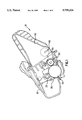
- FIG. 1 is a cross sectional elevation view of a laser printer toner cartridge (consumable) having a messaging device connected thereto for providing information regarding the consumable under principles of the present invention.
- FIG. 2 is a cross sectional elevation view showing the toner cartridge inserted within a host electrophotographic printer.
- FIG. 3 is a perspective view of the toner cartridge showing one embodiment of a messaging device attached to the cartridge.
- FIG. 4 is a top plan view of one embodiment of the messaging device.
- FIG. 5 is a top plan view of the messaging device displaying an exemplary message of "toner low" in response to a signal applied thereto.
- FIG. 6 is a top plan view of a fuse that when combined with the messaging device provides an alternate embodiment messaging system.
- FIG. 7 is a top plan view of the messaging device depicting how multiple messages may be embodied in one messaging device, visualized in response to a variety of control signals received.
- FIG. 1 is a cross sectional elevation view of a laser printer toner cartridge (consumable) 10 having messaging device 15 connected thereto.
- Messaging device 15 provides visual use status (or life status) indicia and/or product identification information regarding the consumable in response to a signal supplied thereto.
- the present invention messaging system is disclosed in reference to toner cartridge 10 for a host laser printer 12 (FIG. 2).
- FIG. 2 the principles are also applicable to other consumable products, imaging systems, and/or electrical systems.
- Cartridge 10 includes photoconductive drum roller 20, charge roller 25, developer 30, cleaning blade 35, toner reservoir (hopper) 40 with toner agitator 45, and "toner low” sensor (antennae) 50.
- Messaging device (or label) 15 is securely attached to cartridge 10 in a manner such that the functional operation of the cartridge is not disturbed in connection with its intended use in a host laser printer. However, it is attached so as to receive a control signal from the host printer, the signal being indicative of a use or life status (jointly referred to herein as "use” status) of cartridge 10.
- the signal may be transmitted to messaging device 15 via a form of light wave transmission, such as infrared or light emitting diode, or via an electrically conductive or inductive connection.
- messaging device 15 connects to its host via electrical contact points.
- cartridge 10 self generates the control signal transmitted to messaging device 15.
- Messaging device 15 is attached to cartridge 10 so as to be clearly visible by a user or manufacturer for interpreting any message displayed on the messaging device. It is preferable to be able to visually observe messaging device 15 when cartridge 10 is mated or inserted within its host, as well as when it is extracted from the host. However, for simplicity of electrical connection, it is preferable to place the messaging device 15 as shown for ease of interfacing with the host. Messaging device 15 is attached to cartridge 10 using any conventional means in the art, such as adhesive, screw, rivet, etc.
- FIG. 2 is a cross sectional elevation view showing cartridge 10 inserted within host electrophotographic (EP) printer 12.
- printer 12 includes feed rollers 13 and 14 for feeding the printing sheets stacked in the printing sheet cassettes 16 and 17, a pair of rollers 21 for conveying a printing sheet fed from the printing sheet cassettes 16 or 17, and a pair of heat rollers 23 for fixing the toner transferred on the printing sheet.
- printer 12 includes contact element 27 for connecting with messaging device 15 of cartridge 10 for transmitting of a control signal.
- FIG. 3 is a perspective view of toner cartridge 10 showing messaging device 15 attached to the cartridge in one embodiment.
- Messaging device 15 is positioned on the cartridge so that electrical contacts 65 interface with contacts 27 on host 12.
- messaging device 15 could be attached to cartridge 10 at various locations of the cartridge, so long as the host's contacts 27 are repositioned to appropriately mate with contacts 65.
- FIG. 4 is a top view of messaging device 15 having body 55, electrodes 60, and electrical contacts 65.
- Body 55 is a resistive heater substrate which heats in response to an electrical voltage signal applied at electrodes 60 through contacts 65.
- Resistive heater 55 may be formed from any number of conventional materials in the art, such as silver conductive ink, aluminum, etc., and is formed to design criteria specific to the application at hand as described further herein. Namely, the conductive material, thickness, resistance, etc., of body 55 are dependent upon electrical properties desired for purposes described herein and as known to those of ordinary skill in the art.
- thermochromatic ink 70 is screen printed over body 55 and changes color in response to heat generated from resistive heater 55.
- Thermochromatic ink 70 may be a reversible or non reversible ink as well known in the art.
- the combination of resistive heater 55 and thermochromatic ink 70 provide an effective messaging means for consumable 10. For example, a message is first imprinted or screened on resistive heater 55, and then a dark (opaque) color thermochromatic ink is subsequently screened over the message on the resistive heater to hide the message.
- resistive heater 55 heats and causes thermochromatic ink 70 to change to a clear (transparent) color such that the message becomes visually perceptible.
- FIG. 5 shows an example of how a message of "toner low” appears after heating resistive heater 55 in response to a signal applied at contacts 65.
- this "toner low” message is especially useful to a consumer or manufacturer who needs to know the toner level in toner cartridge 10 (FIG. 1).
- the message is hidden by thermochromatic ink 70 when the toner supply is not low, but becomes visible when the printer senses the toner level is low (by any conventional means, such as toner sensor/antennae 50 of FIG. 1).
- the printer then generates a signal that is applied to contacts 65, sufficient to heat body 55 and to cause ink 70 to change to its transparent color for displaying the message.
- cartridge 10 is configured to generate its own signal to be transmitted to messaging device 15 upon sensing the low toner level.
- Messaging device 15 may be formed according to various configurations and electrical properties that are dependent only upon design criteria for the messaging system as a whole, including physical and electrical properties of consumable 10 and host 12.
- a reversible chromatic ink label changed from black to clear with four (4) volts and 1.25 amps applied at contacts 65 in one minute of elapsed time.
- Resistive heater 55 achieved 180° F. and the ink was completely changed from opaque to transparent. Since a reversible ink was used, the ink changed back to black when subjected to 50° F. for a short period of time.
- the resistive heater was formed from silver conductive ink at about 0.0005 inch thickness.
- This example demonstrates how an electrical control signal produces a visual effect upon the messaging device such that a message may be displayed for whatever purpose.
- the reversible ink is not preferred because the message may be inadvertently reversed and hidden again. Rather, if a non reversible ink were used, a message such as "toner low” could be placed on body 55 under the ink, and when the ink changed color, the "toner low” message would appear and remain permanently visible for a user or manufacturer to see.
- a non-reversible chromatic ink label changed from clear to black with four (4) volts at 1.25 amps in one minute elapsed time.
- Resistive heater 55 achieved 200° F. and the ink completely changed from transparent to opaque.
- the resistive heater was formed from silver conductive ink at about 0.0005 inch thickness.
- This example demonstrates an alternate usage for effectuating a message through messaging device 15.
- This form of messaging allows a manufacturer to place its trade name (or the product name, or the like) on body 55, and have the name remain visible to the consumer, due to the transparent ink, prior to a control signal being applied through contacts 65. However, once a signal is applied, the ink darkens to hide the name.
- the product is recognized as an authorized product with the trade name (or product name) visible when the cartridge is new. Once the cartridge is spent, the name disappears. The name will then be reinstated only by an authorized entity when the cartridge is refilled or remanufactured. If the name is not visible when the cartridge is new (refilled or remanufactured), then the consumer may know that it is not an authorized product.
- ink 70 and resistive heater 55 may, optionally, be designed to respond to different electrical properties such that varying temperatures are generated by the heater to render different color change activation levels in the ink.
- fuse 75 is depicted that, in an alternate embodiment of the present invention, is combined with messaging device 15 by overlaying messaging device 15 over fuse 75 to form an "integrated" messaging device.
- Fuse 75 has a thin middle cross section 80 that is burned out or "blown” when too much current is applied therethrough via electrical contacts 85.
- Fuse 75 may be of a conventional fuse material, such as silver ink.
- An exemplary fuse was constructed at 0.2 inches in length, 0.002 inches in width, and blew in one second at four volts and 1.15 amps.
- fuse 75 could be used alone in connection with a consumable to display a "message" to the user (the message being understood by the fact that the fuse has or has not been blown) it is preferable to integrate the fuse with messaging device 15 for attachment to consumable 10 or the like. Similar to messaging device 15, a signal is applied to contacts 85 (by a host to which the consumable is mated) upon some identified event occurring to the consumable. During processing, the host recognizes (detects) when and if the fuse is blown and operates accordingly as delineated by design criteria set for the system.
- the host can blow fuse 75 on the cartridge, either alone or in addition to displaying a message through messaging device 15. Subsequently, any time that same cartridge is inserted (with the blown fuse), the printer can quickly and easily detect that the fuse is blown and that the cartridge is low on toner.
- Another implementation for the messaging device and messaging system of the present invention includes attaching a plurality of the messaging devices (and/or fuses) to a consumable such that multiple messages are displayable or a "gradation gauge" is created thereby.
- a single messaging device is formed to include a plurality of messages thereon such that each message is capable of being legibly discerned upon the occurrence of a distinguishing event.
- a plurality of fuses 75 may be connected, with each being designated to blow in response to a distinguishing event (i.e., in response to a specific voltage or amperage).
- one messaging device 15 includes various messages thereon: "Toner Full”, “Half Full” and “Toner Low”. Each message is screened over by a thermochromatic ink 90, 95 and 100 that is chosen to change color at a specifically chosen applied signal, i.e., a different amperage or voltage.
- a specifically chosen applied signal i.e., a different amperage or voltage.
- ink 90 is clear so that the "Toner Full” message remains visible, and ink 95 and 100 are opaque so those messages are hidden.
- the correct amperage is applied to contacts 65 to cause ink 95 over the "Half Full” message to change to clear such that the message can be read.
- ink 90 over the "Toner Full” message changes to dark such that the "Toner Full” message can no longer be read.
- a first fuse 75 may be blown, indicative of a "half full” status, so that the printer system knows immediately what the status is upon extraction and reinsertion of the cartridge.
- toner level when the toner level is detected as being low, a different level of amperage is applied to cause screened ink 100 over the "Toner Low” message to become clear such that the message can be read. Simultaneously, the ink over the "Half Full” message changes to dark such that it can no longer be read.
- a second fuse may be blown, indicative of a "toner low” status so that the printer system knows immediately what the status of the cartridge is upon extraction and reinsertion into the printer system.
- messaging device 15 and/or fuse 75 have no need of receiving any electrical signal through contact terminals 65 and/or 85. Rather, cross section 80 is blown or a message on body 55 is thermally visualized in response to environmental conditions around cartridge 10, such as by heat generated from printer system 12 (FIG. 2). Specifically, printer cartridge compartment 105 (FIG. 2) experiences elevated temperatures during printer operation. For example, temperatures in excess of 45° C. have been measured in such a compartment, mostly generated by fuser rollers 23.
- thermochromatic ink 70 and/or fuse 75 are designed to respond to the elevated temperature and thereby, respectively, (i) automatically cause the ink to change color such that a message is displayed on the messaging device, and/or (ii) automatically cause the fuse to blow.
- An example of usage for this type of messaging device is to indicate, simply, that the cartridge has been used. Namely, an unambiguous method of indicating cartridge use is provided by firmly affixing messaging device 15 to the exterior of cartridge 10 and causing the messaging device to develop a "used cartridge" message when exposed to the elevated temperatures of compartment 105.
- the messaging device (and/or fuse) is permanently attached to the cartridge with a permanent adhesive. After a short period of cartridge use, the heat from the printer will develop the message on the messaging device to indicate the cartridge has been used. This permanently marks the cartridge as a used item, thereby reducing the opportunity for fraud. Attempts to remove the messaging device will produce obvious damage to the cartridge, further indicating tampering, and thereby reducing attempts at fraudulent marketing, refurbishing, refilling, etc. of the cartridge.
- messaging device 15 and optional fuse 75 in connection with a consumable product (such as cartridge 10), serve to provide a message or a change in message on the exterior of the consumable at a desired time (i.e., "toner low", “exhausted”, etc.) in response to a control signal applied thereto.
- the messaging device provides at least two states for communicating messages, including a first state prior to receiving the control signal, and at least a second state after having received the control signal. Thus, a message or a change in message is displayed, depending upon the state or frame of reference.
- the power requirements for producing the reaction in the messaging device and/or fuse are, preferably, within the voltage and amperage available in the host (i.e., printer system in this example).
- Fuse 75 provides an additional means for detecting the life status of the product. In alternate-embodiments, messaging device 15 and fuse 75 are activated by elevated temperatures rather than direct control signals. Advantages of the present invention messaging system include:
Abstract
Description
Claims (19)
Priority Applications (4)
| Application Number | Priority Date | Filing Date | Title |
|---|---|---|---|
| US08/716,754 US5758224A (en) | 1996-09-23 | 1996-09-23 | Fusable life indicator and identification device for an electrophotographic consumable product |
| DE69716692T DE69716692T2 (en) | 1996-09-23 | 1997-04-10 | Consumable product with lifespan display and image-producing device with this consumable product |
| EP97105959A EP0831379B1 (en) | 1996-09-23 | 1997-04-10 | Consumable product having a life indicator and image forming device compsiing said consumable product |
| JP9252190A JPH10105005A (en) | 1996-09-23 | 1997-09-17 | Consumables for electrophotographic device |
Applications Claiming Priority (1)
| Application Number | Priority Date | Filing Date | Title |
|---|---|---|---|
| US08/716,754 US5758224A (en) | 1996-09-23 | 1996-09-23 | Fusable life indicator and identification device for an electrophotographic consumable product |
Publications (1)
| Publication Number | Publication Date |
|---|---|
| US5758224A true US5758224A (en) | 1998-05-26 |
Family
ID=24879302
Family Applications (1)
| Application Number | Title | Priority Date | Filing Date |
|---|---|---|---|
| US08/716,754 Expired - Lifetime US5758224A (en) | 1996-09-23 | 1996-09-23 | Fusable life indicator and identification device for an electrophotographic consumable product |
Country Status (4)
| Country | Link |
|---|---|
| US (1) | US5758224A (en) |
| EP (1) | EP0831379B1 (en) |
| JP (1) | JPH10105005A (en) |
| DE (1) | DE69716692T2 (en) |
Cited By (30)
| Publication number | Priority date | Publication date | Assignee | Title |
|---|---|---|---|---|
| US5943525A (en) * | 1997-02-28 | 1999-08-24 | Brother Kogyo Kabushiki Kaisha | Toner remaining detection unit in an image forming apparatus |
| US6091915A (en) * | 1995-11-10 | 2000-07-18 | Canon Kabushiki Kaisha | Image forming apparatus with independent displays |
| US6106088A (en) * | 1997-10-01 | 2000-08-22 | Xerox Corporation | Printhead assembly with integral lifetime monitoring system |
| US6205298B1 (en) * | 1997-10-28 | 2001-03-20 | Sharp Kabushiki Kaisha | Image forming apparatus, and recycle processing apparatus for recycling image forming unit |
| US6215966B1 (en) * | 1998-09-15 | 2001-04-10 | Samsung Electronics Co., Ltd. | Apparatus and method to identify replacement of developing machine |
| US6263170B1 (en) | 1999-12-08 | 2001-07-17 | Xerox Corporation | Consumable component identification and detection |
| US6324350B1 (en) | 1998-12-25 | 2001-11-27 | Casio Computer Co., Ltd. | Reusable unit displaying a specific pattern and an image forming apparatus using the reusable unit when the specific pattern is displayed and rendering the specific pattern illegible when the reusable unit is exhausted |
| US6456802B1 (en) | 2001-04-02 | 2002-09-24 | Hewlett-Packard Co. | Capacity determination for toner or ink cartridge |
| US6487378B1 (en) * | 2001-10-17 | 2002-11-26 | Toshiba Tec Kabushiki Kaisha | Electrophotographic apparatus, main unit and sub-unit, both for use in the electrophotographic apparatus, and method of identifying the sub-unit |
| US20030035128A1 (en) * | 2001-08-16 | 2003-02-20 | Phillips Quintin T. | Image forming devices, methods of operating an image forming device, a method of providing consumable information, and a method of operating a printer |
| US6532346B2 (en) * | 2001-08-02 | 2003-03-11 | Hewlett-Packard Company | Systems and methods for printing shipping labels for recycling printing device replaceable components |
| US6654577B1 (en) | 2002-10-24 | 2003-11-25 | Hewlett-Packard Development Company, L.P. | Toner cartridge converter |
| US20040125160A1 (en) * | 2002-12-30 | 2004-07-01 | Anderson Frank Edward | Method of warning a user of end of life of a consumable for an ink jet printer |
| US20040207668A1 (en) * | 2003-04-18 | 2004-10-21 | Adkins Christopher A. | Method of estimating an amount of available ink contained in an ink reservoir |
| US20040212643A1 (en) * | 2003-04-25 | 2004-10-28 | King William F. | Ink level sensing |
| US20050151776A1 (en) * | 2004-01-12 | 2005-07-14 | Bruce Johnson | Printer component |
| US6961531B2 (en) | 2002-10-17 | 2005-11-01 | Hewlett-Packard Development Company, L.P. | Refillable print cartridge and method of refilling |
| US20050270314A1 (en) * | 2004-06-04 | 2005-12-08 | Ehlert Jeffrey R | Method of ink evaporation prediction for an ink reservoir |
| US20060098084A1 (en) * | 2004-10-27 | 2006-05-11 | Phillips Quintin T | Marking replaceable resource units within printing devices |
| US20060177230A1 (en) * | 2005-01-20 | 2006-08-10 | Brother Kogyo Kabushiki Kaisha | Image forming apparatus and developer cartridge |
| US20060279127A1 (en) * | 2005-06-09 | 2006-12-14 | Cronin John E | Apparatus including a selective interface system between two sub-components |
| US20070071463A1 (en) * | 2005-09-28 | 2007-03-29 | Kendall David R | Marking device and methods |
| US20070273333A1 (en) * | 2006-05-23 | 2007-11-29 | Ultralife Batteries, Inc. | Complete discharge device |
| WO2009042600A3 (en) * | 2007-09-26 | 2009-06-04 | Hewlett Packard Development Co | System and method for providing messages on a printing component |
| WO2010087846A1 (en) * | 2009-01-30 | 2010-08-05 | Hewlett-Packard Development Company, L.P. | System and method for providing a message on a replaceable printing component |
| US20110156497A1 (en) * | 2009-12-31 | 2011-06-30 | Ultralife Corporation | System and method for activating an isolated device |
| US20110254907A1 (en) * | 2007-08-10 | 2011-10-20 | Samsung Electronics Co., Ltd. | Image forming apparatus, cartridge and image forming method |
| US20120249076A1 (en) * | 2009-10-21 | 2012-10-04 | Continental Automotive Gmbh | Electric energy store having an integrated deep discharge device |
| US9964891B2 (en) * | 2014-12-17 | 2018-05-08 | Lexmark International, Inc. | Systems for optical communication between an image forming device and a replaceable unit of the image forming device |
| CN113287068A (en) * | 2018-11-05 | 2021-08-20 | 利盟国际有限公司 | Toner cartridge with locating feature |
Families Citing this family (5)
| Publication number | Priority date | Publication date | Assignee | Title |
|---|---|---|---|---|
| GB9715774D0 (en) * | 1997-07-26 | 1997-10-01 | Thompson Peter B | Cartridge |
| US20030067378A1 (en) * | 2001-10-04 | 2003-04-10 | Baarman David W. | End-of-life indicator |
| WO2011127334A2 (en) | 2010-04-08 | 2011-10-13 | Access Business Group International Llc | Point of sale inductive systems and methods |
| CA2775546A1 (en) * | 2012-04-25 | 2013-10-25 | Intelligent Devices Inc. | A disposable content use monitoring package with indicator and method of making same |
| DE102014003243A1 (en) * | 2014-03-11 | 2015-09-17 | Polysecure Gmbh | Component with originality marker and usage indicator, component-containing equipment or machine and method for checking a component |
Citations (1)
| Publication number | Priority date | Publication date | Assignee | Title |
|---|---|---|---|---|
| US5202677A (en) * | 1991-01-31 | 1993-04-13 | Crystal Images, Inc. | Display apparatus using thermochromic material |
Family Cites Families (10)
| Publication number | Priority date | Publication date | Assignee | Title |
|---|---|---|---|---|
| JPS57163276A (en) * | 1981-04-01 | 1982-10-07 | Canon Inc | Picture forming device |
| JPS5961851A (en) * | 1982-09-30 | 1984-04-09 | Canon Inc | Display mechanism for life of process cartridge |
| JPS60177546A (en) * | 1984-02-22 | 1985-09-11 | Toshiba Corp | Fluorescent lamp |
| JPS60243524A (en) * | 1984-05-18 | 1985-12-03 | Ricoh Co Ltd | Part-replacing-time display sensor |
| JPS6243655A (en) * | 1985-08-21 | 1987-02-25 | Canon Inc | Image forming device |
| US4961088A (en) * | 1989-04-20 | 1990-10-02 | Xerox Corporation | Monitor/warranty system for electrostatographic reproducing machines using replaceable cartridges |
| DE9004494U1 (en) * | 1990-04-20 | 1990-06-28 | Kpv-Keilbach Gmbh, 7102 Weinsberg, De | |
| JPH063890A (en) * | 1992-06-24 | 1994-01-14 | Toshiba Corp | Image forming device |
| JPH08235828A (en) * | 1995-03-01 | 1996-09-13 | Hitachi Ltd | Magnetic disk-card |
| JPH096196A (en) * | 1995-06-20 | 1997-01-10 | Canon Inc | Image forming device |
-
1996
- 1996-09-23 US US08/716,754 patent/US5758224A/en not_active Expired - Lifetime
-
1997
- 1997-04-10 DE DE69716692T patent/DE69716692T2/en not_active Expired - Fee Related
- 1997-04-10 EP EP97105959A patent/EP0831379B1/en not_active Expired - Lifetime
- 1997-09-17 JP JP9252190A patent/JPH10105005A/en active Pending
Patent Citations (1)
| Publication number | Priority date | Publication date | Assignee | Title |
|---|---|---|---|---|
| US5202677A (en) * | 1991-01-31 | 1993-04-13 | Crystal Images, Inc. | Display apparatus using thermochromic material |
Cited By (50)
| Publication number | Priority date | Publication date | Assignee | Title |
|---|---|---|---|---|
| US6091915A (en) * | 1995-11-10 | 2000-07-18 | Canon Kabushiki Kaisha | Image forming apparatus with independent displays |
| US5943525A (en) * | 1997-02-28 | 1999-08-24 | Brother Kogyo Kabushiki Kaisha | Toner remaining detection unit in an image forming apparatus |
| US6106088A (en) * | 1997-10-01 | 2000-08-22 | Xerox Corporation | Printhead assembly with integral lifetime monitoring system |
| US6205298B1 (en) * | 1997-10-28 | 2001-03-20 | Sharp Kabushiki Kaisha | Image forming apparatus, and recycle processing apparatus for recycling image forming unit |
| US6215966B1 (en) * | 1998-09-15 | 2001-04-10 | Samsung Electronics Co., Ltd. | Apparatus and method to identify replacement of developing machine |
| US6324350B1 (en) | 1998-12-25 | 2001-11-27 | Casio Computer Co., Ltd. | Reusable unit displaying a specific pattern and an image forming apparatus using the reusable unit when the specific pattern is displayed and rendering the specific pattern illegible when the reusable unit is exhausted |
| US6263170B1 (en) | 1999-12-08 | 2001-07-17 | Xerox Corporation | Consumable component identification and detection |
| US6456802B1 (en) | 2001-04-02 | 2002-09-24 | Hewlett-Packard Co. | Capacity determination for toner or ink cartridge |
| US6532346B2 (en) * | 2001-08-02 | 2003-03-11 | Hewlett-Packard Company | Systems and methods for printing shipping labels for recycling printing device replaceable components |
| DE10232956B4 (en) * | 2001-08-16 | 2012-09-13 | Hewlett-Packard Development Co., L.P. | An image forming apparatus with prediction of consumption of a consumable and method of operating the same |
| US7145671B2 (en) | 2001-08-16 | 2006-12-05 | Hewlett-Packard Development Company, L.P. | Image forming devices, methods of operating an image forming device, a method of providing consumable information, and a method of operating a printer |
| US20030035128A1 (en) * | 2001-08-16 | 2003-02-20 | Phillips Quintin T. | Image forming devices, methods of operating an image forming device, a method of providing consumable information, and a method of operating a printer |
| US6487378B1 (en) * | 2001-10-17 | 2002-11-26 | Toshiba Tec Kabushiki Kaisha | Electrophotographic apparatus, main unit and sub-unit, both for use in the electrophotographic apparatus, and method of identifying the sub-unit |
| US6961531B2 (en) | 2002-10-17 | 2005-11-01 | Hewlett-Packard Development Company, L.P. | Refillable print cartridge and method of refilling |
| US6654577B1 (en) | 2002-10-24 | 2003-11-25 | Hewlett-Packard Development Company, L.P. | Toner cartridge converter |
| US20050195237A1 (en) * | 2002-12-30 | 2005-09-08 | Laxmark International, Inc. | Method of informing a user of end of life of a consumable for an ink jet printer |
| US6962399B2 (en) | 2002-12-30 | 2005-11-08 | Lexmark International, Inc. | Method of warning a user of end of life of a consumable for an ink jet printer |
| US7258411B2 (en) | 2002-12-30 | 2007-08-21 | Lexmark International, Inc. | Method of informing a user of end of life of a consumable for an ink jet printer |
| US20040125160A1 (en) * | 2002-12-30 | 2004-07-01 | Anderson Frank Edward | Method of warning a user of end of life of a consumable for an ink jet printer |
| US6871926B2 (en) | 2003-04-18 | 2005-03-29 | Lexmark International, Inc. | Method of estimating an amount of available ink contained in an ink reservoir |
| US20040207668A1 (en) * | 2003-04-18 | 2004-10-21 | Adkins Christopher A. | Method of estimating an amount of available ink contained in an ink reservoir |
| US6848762B2 (en) | 2003-04-25 | 2005-02-01 | Hewlett-Packard Development Company, L.P. | Ink level sensing |
| US20040212643A1 (en) * | 2003-04-25 | 2004-10-28 | King William F. | Ink level sensing |
| US7101014B2 (en) | 2004-01-12 | 2006-09-05 | Hewlett-Packard Development Company, L.P. | Printer component |
| US20050151776A1 (en) * | 2004-01-12 | 2005-07-14 | Bruce Johnson | Printer component |
| US20050270314A1 (en) * | 2004-06-04 | 2005-12-08 | Ehlert Jeffrey R | Method of ink evaporation prediction for an ink reservoir |
| US7766438B2 (en) | 2004-06-04 | 2010-08-03 | Lexmark International, Inc. | Method of ink evaporation prediction for an ink reservoir |
| US7333125B2 (en) | 2004-10-27 | 2008-02-19 | Hewlett-Packard Development Company, L.P. | Marking replaceable resource units within printing devices |
| US20060098084A1 (en) * | 2004-10-27 | 2006-05-11 | Phillips Quintin T | Marking replaceable resource units within printing devices |
| US7444087B2 (en) * | 2005-01-20 | 2008-10-28 | Brother Kogyo Kabushiki Kaisha | Image forming apparatus and developer cartridge with power supply shielding mechanism |
| US20060177230A1 (en) * | 2005-01-20 | 2006-08-10 | Brother Kogyo Kabushiki Kaisha | Image forming apparatus and developer cartridge |
| US20060279127A1 (en) * | 2005-06-09 | 2006-12-14 | Cronin John E | Apparatus including a selective interface system between two sub-components |
| US20080116295A1 (en) * | 2005-06-09 | 2008-05-22 | Cronin John E | Apparatus including a selective interface system between two sub-components |
| US20080118255A1 (en) * | 2005-06-09 | 2008-05-22 | Cronin John E | Apparatus including a selective interface system between two sub-components |
| US20070071463A1 (en) * | 2005-09-28 | 2007-03-29 | Kendall David R | Marking device and methods |
| US7555229B2 (en) | 2005-09-28 | 2009-06-30 | Hewlett-Packard Development Company, L.P. | Marking device and methods |
| US7586289B2 (en) | 2006-05-23 | 2009-09-08 | Ultralife Corporation | Complete discharge device |
| US20070273333A1 (en) * | 2006-05-23 | 2007-11-29 | Ultralife Batteries, Inc. | Complete discharge device |
| US8301042B2 (en) * | 2007-08-10 | 2012-10-30 | Samsung Electronics Co., Ltd. | Image forming apparatus, cartridge and image forming method |
| US20110254907A1 (en) * | 2007-08-10 | 2011-10-20 | Samsung Electronics Co., Ltd. | Image forming apparatus, cartridge and image forming method |
| US7620333B2 (en) | 2007-09-26 | 2009-11-17 | Hewlett-Packard Development Company, L.P. | System and method for providing messages on a printing component |
| WO2009042600A3 (en) * | 2007-09-26 | 2009-06-04 | Hewlett Packard Development Co | System and method for providing messages on a printing component |
| WO2010087846A1 (en) * | 2009-01-30 | 2010-08-05 | Hewlett-Packard Development Company, L.P. | System and method for providing a message on a replaceable printing component |
| US8693899B2 (en) | 2009-01-30 | 2014-04-08 | Hewlett-Packard Development Company, L.P. | System and method for providing a message on a replaceable printing component |
| US20120249076A1 (en) * | 2009-10-21 | 2012-10-04 | Continental Automotive Gmbh | Electric energy store having an integrated deep discharge device |
| US9825340B2 (en) * | 2009-10-21 | 2017-11-21 | Continental Automotive Gmbh | Electric energy storage device having a radio-controlled switch for discharging energy using an integrated deep discharge device |
| US20110156497A1 (en) * | 2009-12-31 | 2011-06-30 | Ultralife Corporation | System and method for activating an isolated device |
| US8928190B2 (en) | 2009-12-31 | 2015-01-06 | Ultralife Corporation | System and method for activating an isolated device |
| US9964891B2 (en) * | 2014-12-17 | 2018-05-08 | Lexmark International, Inc. | Systems for optical communication between an image forming device and a replaceable unit of the image forming device |
| CN113287068A (en) * | 2018-11-05 | 2021-08-20 | 利盟国际有限公司 | Toner cartridge with locating feature |
Also Published As
| Publication number | Publication date |
|---|---|
| JPH10105005A (en) | 1998-04-24 |
| EP0831379A2 (en) | 1998-03-25 |
| EP0831379A3 (en) | 1998-06-03 |
| DE69716692T2 (en) | 2003-08-14 |
| EP0831379B1 (en) | 2002-10-30 |
| DE69716692D1 (en) | 2002-12-05 |
Similar Documents
| Publication | Publication Date | Title |
|---|---|---|
| US5758224A (en) | Fusable life indicator and identification device for an electrophotographic consumable product | |
| EP0873873B1 (en) | Image forming and office automation device consumable with memory | |
| US20020194064A1 (en) | Methods and apparatus for promoting use of consumable goods in imaging devices | |
| EP0808720B1 (en) | Image forming device with end of life messaging for consumables | |
| US6584290B2 (en) | System for providing information for a customer replaceable unit | |
| US6332062B1 (en) | Systems and methods for customizing user messages in a printing system | |
| EP1123810A2 (en) | Image forming device with token printing capabilities for replacement of consumables | |
| JP2001018507A (en) | Image recorder | |
| KR100553897B1 (en) | Apparatus for managing consumption goods of image forming apparatus by using memory | |
| JP3413802B2 (en) | Dynamic estimation of supply usage | |
| EP1522903A2 (en) | Image forming apparatus and cartridge detachably attachable thereto | |
| US7620333B2 (en) | System and method for providing messages on a printing component | |
| CN103135391B (en) | Electronic apparatus and image forming apparatus | |
| US20020108439A1 (en) | Systems and methods for displaying status of consumable resource | |
| US6975422B2 (en) | Method for providing information for a customer replaceable unit | |
| JP3522608B2 (en) | Replacement part recognition device and image forming device | |
| JP2008058741A (en) | Image forming apparatus | |
| CN103676530A (en) | Packaged image forming apparatus and diagnostic system of apparatus to be packaged | |
| US10409211B2 (en) | Image forming apparatus | |
| JP3897505B2 (en) | Anomaly detection system | |
| US20030072028A1 (en) | Image forming devices and methods of forming hard images | |
| US20110279865A1 (en) | System and method for providing a message on a replaceable printing component | |
| JP2005257816A (en) | Printer | |
| CN217347194U (en) | Printing device with automatic detecting print head dead pixel function | |
| JP3095015B1 (en) | Consumable unit and image forming apparatus using the same |
Legal Events
| Date | Code | Title | Description |
|---|---|---|---|
| AS | Assignment |
Owner name: HEWLETT-PACKARD COMPANY, CALIFORNIA Free format text: ASSIGNMENT OF ASSIGNORS INTEREST;ASSIGNORS:BINDER, ANDREW J.;CHRISTENSEN, K. TRENT;PHILLIPS, QUINTIN T.;REEL/FRAME:008411/0180 Effective date: 19960920 |
|
| STCF | Information on status: patent grant |
Free format text: PATENTED CASE |
|
| FEPP | Fee payment procedure |
Free format text: PAYOR NUMBER ASSIGNED (ORIGINAL EVENT CODE: ASPN); ENTITY STATUS OF PATENT OWNER: LARGE ENTITY |
|
| AS | Assignment |
Owner name: HEWLETT-PACKARD COMPANY, COLORADO Free format text: MERGER;ASSIGNOR:HEWLETT-PACKARD COMPANY;REEL/FRAME:011523/0469 Effective date: 19980520 |
|
| FPAY | Fee payment |
Year of fee payment: 4 |
|
| FPAY | Fee payment |
Year of fee payment: 8 |
|
| FPAY | Fee payment |
Year of fee payment: 12 |
|
| AS | Assignment |
Owner name: HEWLETT-PACKARD DEVELOPMENT COMPANY, L.P., TEXAS Free format text: ASSIGNMENT OF ASSIGNORS INTEREST;ASSIGNOR:HEWLETT-PACKARD COMPANY;REEL/FRAME:026945/0699 Effective date: 20030131 |