US5754992A - Lifting frame - Google Patents
Lifting frame Download PDFInfo
- Publication number
- US5754992A US5754992A US08/450,081 US45008195A US5754992A US 5754992 A US5754992 A US 5754992A US 45008195 A US45008195 A US 45008195A US 5754992 A US5754992 A US 5754992A
- Authority
- US
- United States
- Prior art keywords
- hanger
- hammock
- beams
- connection means
- connect
- Prior art date
- Legal status (The legal status is an assumption and is not a legal conclusion. Google has not performed a legal analysis and makes no representation as to the accuracy of the status listed.)
- Expired - Fee Related
Links
- 239000000725 suspension Substances 0.000 claims description 5
- 238000010276 construction Methods 0.000 description 4
- 230000003466 anti-cipated effect Effects 0.000 description 2
- 239000000463 material Substances 0.000 description 2
Images


Classifications
-
- A—HUMAN NECESSITIES
- A61—MEDICAL OR VETERINARY SCIENCE; HYGIENE
- A61G—TRANSPORT, PERSONAL CONVEYANCES, OR ACCOMMODATION SPECIALLY ADAPTED FOR PATIENTS OR DISABLED PERSONS; OPERATING TABLES OR CHAIRS; CHAIRS FOR DENTISTRY; FUNERAL DEVICES
- A61G7/00—Beds specially adapted for nursing; Devices for lifting patients or disabled persons
- A61G7/10—Devices for lifting patients or disabled persons, e.g. special adaptations of hoists thereto
- A61G7/1049—Attachment, suspending or supporting means for patients
- A61G7/1055—Suspended platforms, frames or sheets for patient in lying position
-
- A—HUMAN NECESSITIES
- A61—MEDICAL OR VETERINARY SCIENCE; HYGIENE
- A61G—TRANSPORT, PERSONAL CONVEYANCES, OR ACCOMMODATION SPECIALLY ADAPTED FOR PATIENTS OR DISABLED PERSONS; OPERATING TABLES OR CHAIRS; CHAIRS FOR DENTISTRY; FUNERAL DEVICES
- A61G7/00—Beds specially adapted for nursing; Devices for lifting patients or disabled persons
- A61G7/10—Devices for lifting patients or disabled persons, e.g. special adaptations of hoists thereto
- A61G7/1049—Attachment, suspending or supporting means for patients
- A61G7/1061—Yokes
Definitions
- This invention relates to a frame and a sling or hammock for a lifting device to temporarily support an incapacitated person in an elevated horizontal position while being transported from one location to another.
- U.S. Pat. No. 4,190,912 discloses a ceiling mounted lifting device having a rigid carrier arm and a transfer means for lateral movement of the arm. The arms are pivotally connected to depending link members which support a sling apparatus that holds a patient in a horizontal position during transport.
- Other types of lifting devices of different constructions are disclosed in U.S. Pat. Nos. 3,882,555, 4,739,526 and 5,072,840.
- U.S. Pat. No. 4,920,590 discloses a floor traversing crane with a cantilevered arm from which a hanger 22 may be hung to support a belt device (not shown in the patent).
- the present invention provides a hammock and frame combination
- a hanger having a crane connection means to connect onto a lifting device and having first and second hanger arms depending downwardly and outwardly from said connection means and ending at a bracket; first and second frames, each said frame having a beam and a plurality of ribs spaced apart along said beam, and each said beam having at one end thereof a slot to connect with a bracket of one of the hanger arms to cantilever the beam outwardly therefrom, and each said rib having rib hook means at each end thereof to permit a hammock to be hung therefrom, and a hammock to underlie and support a person in a prone position having loop means to connect over the rib hooks means to hang the hammock from the frames.
- the hanger is a standard feature of certain floor cranes and this invention is intended in part to adapt such floor cranes to transportation of persons in a horizontal position.
- Certain known hangers are shaped similarly to a common clothes hanger but are constructed in materials and shapes to support heavy loads and have upward curving hooks at an end of each of two downward and outward extending hanger arms. (The term “outwardly” means away from the crane connection means in a plane containing the hanger arms).
- Each beam of this invention has a slot that receives an upwardly curving end of one of the hanger arms when the slot is angled upwards and outwards from the end and connects with the end as the beam is angled downwards to a horizontal position.
- the beams are constructed from materials and in structural forms suitable to withstanding anticipated forces. Each of the beams may be further supported at its ends or along its length by a tensile member running from a position on the crane or hanger and having depending tensile members connected to the beam along its length to form a suspension truss.
- the tensile member is a wire running from the crane connection to the ends of the beam members.
- each beam is pivotally connected to permit them to be rotated to a position parallel to the beam for storage in a more compact form.
- the ribs at fastened along the beam with their fulcrums at different lateral positions so that the ribs may be rotated over the beam and lie parallel to one another.
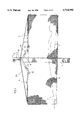
- FIG. 1 is a side view showing a person lying in an elevated horizontal position
- FIG. 2 is an overhead prospective view
- FIG. 3 is a detail of the support frame in folded and unfolded positions.
- FIG. 1 illustrates the invention in combination with a floor crane.
- the construction of the crane is not part of this invention and is not shown in detail but it may be similar to that shown in U.S. Pat. No. 4,920,590.
- a crane column (1) supports a crane arm (2) from which depends a connecting means, such as hook (3).
- a hanger (4) is hung on hook (3) and carries two frames (5) which in turn support a hammock (6) to carry a person (7) lying in a horizontal position.
- the hanger (4) may be hung on the hook (3) by means of any conventional connecting means, such as eyelet (8).
- the hanger (4) has two arms (9) which depend downwardly and outwardly, each terminating in a upwardly curving end (10).
- Each of the frames (5) has a beam (11) with a slot (12) sized large enough to permit the slot (12) to fit over a hanger end (10) but small enough to permit the slot (12) to jam against the inside edge of the hanger arm (9) and the top of the end (10) when the frame (5) is cantilevered horizontally out from the hanger (4). It certain embodiments there may be two slots (12) provided in the beam (11) one which receives the hanger bracket hook (10) and another which catches the end (10) from the underside of the beam (11) to secure the connection. It will be appreciated that other means of connecting the cantilevered frames in within the art and no particular means is essential to this invention.
- the frames (5) each comprise a plurality of ribs, such as (13), (14) and (15) rotatably mounted on a beam (11). Pivot lugs (16, 17 and 18) of the ribs (13, 14 and 15 respectively) are offset from each other longitudinally to permit the ribs (13, 14 and 15) to be rotated in a horizontal plane and laid in parallel alignment over the beam (11).
- the ribs in the folded position are shown in FIG. 3 as 13', 14' and 15' respectively.
- a net (6) may be hung from the outer ends of ribs (14, 15 and 16) to carry a person (7). As shown in FIG. 3 the ends of the ribs may be shaped as grooves (20) to receive a loop to hang the net.
- a suspension truss may be formed to provide additional support for the cantilevered beams (11).
- a tensile member such as a wire (21), may be inserted through the ends of beams (11) and about the hanger eyelet (8). It will be appreciated that additional tensile support members may be added as needed along the length of the beam (11) where heavy loads are anticipated.
- the net (6) of this invention may be slipped under a person (7).
- the hanger (4) may be hung from crane hook (3) and the slots (12) of the beams (11) fitted onto the ends (10) of the hanger arms (9) and connected thereto.
- the ribs (13, 14 and 15) may be rotated at right angles to each beam (11) and a wire (21) may be connected through the ends of the beams (11) and about the eyelet (8).
- the frames (5), thus constructed, may be positioned with the crane above the person (7) lying on the net (6) and the net (6) may be connected into the grooves (20) formed in the ends of the ribs (13, 14 and 15). The crane then elevates the hanger, frame and net assembly to carry the person in a prone position to another location.
- the construction of the frames (5), the slot connection to the hanger (4) and the net (6) facilitate assembly and disassembly.
- the ability of the ribs to fold over the beam (11) and lie parallel to each other permits convenient storage of the frame when it is not in use.
Landscapes
- Health & Medical Sciences (AREA)
- Nursing (AREA)
- Life Sciences & Earth Sciences (AREA)
- Animal Behavior & Ethology (AREA)
- General Health & Medical Sciences (AREA)
- Public Health (AREA)
- Veterinary Medicine (AREA)
- Load-Engaging Elements For Cranes (AREA)
- Invalid Beds And Related Equipment (AREA)
Abstract
A frame, sling and hammock is disclosed to be used with a lifting device to support an incapacitated person in an elevated horizontal position as discussed. The device comprises a hanger to connect to a crane, first and second frames cantilevered from the hanger in opposite directions and a net hammock that is looped over the ends of the frames.
Description
This invention relates to a frame and a sling or hammock for a lifting device to temporarily support an incapacitated person in an elevated horizontal position while being transported from one location to another.
Lifting and transportation of incapacitated people (whether living or dead) is a problem frequently experienced in institutions such as hospitals or morgues, particularly where the individual must be moved in a horizontal position. An incapacitated person may be heavy, limp or rigid, sensitive to change in position, or otherwise awkward to lift and carry from place to place. Therefore it is desirable to have some apparatus to assist in handling such persons. Furthermore, a mechanical means of transportation may be safer that manual handling if it reduces the probability that the person might be dropped, twisted or otherwise strained through human error.
In the prior art there have been many devices disclosed for lifting and moving patients. For example, U.S. Pat. No. 4,190,912 discloses a ceiling mounted lifting device having a rigid carrier arm and a transfer means for lateral movement of the arm. The arms are pivotally connected to depending link members which support a sling apparatus that holds a patient in a horizontal position during transport. Other types of lifting devices of different constructions are disclosed in U.S. Pat. Nos. 3,882,555, 4,739,526 and 5,072,840. U.S. Pat. No. 4,920,590 discloses a floor traversing crane with a cantilevered arm from which a hanger 22 may be hung to support a belt device (not shown in the patent).
It will be appreciated by a person skilled in the art that the present invention is adaptable to many lifting devices but a preferred embodiment of this invention has been described in relation to a crane similar in construction to that shown in U.S. Pat. No. 4,920,590.
It is an object of the present invention to provide a frame and a hammock apparatus for carrying a person in a horizontal position using a crane or similar lifting mechanism wherein the apparatus may be disassembled and folded for convenient storage.
The present invention provides a hammock and frame combination comprising: a hanger having a crane connection means to connect onto a lifting device and having first and second hanger arms depending downwardly and outwardly from said connection means and ending at a bracket; first and second frames, each said frame having a beam and a plurality of ribs spaced apart along said beam, and each said beam having at one end thereof a slot to connect with a bracket of one of the hanger arms to cantilever the beam outwardly therefrom, and each said rib having rib hook means at each end thereof to permit a hammock to be hung therefrom, and a hammock to underlie and support a person in a prone position having loop means to connect over the rib hooks means to hang the hammock from the frames.
The hanger is a standard feature of certain floor cranes and this invention is intended in part to adapt such floor cranes to transportation of persons in a horizontal position. Certain known hangers are shaped similarly to a common clothes hanger but are constructed in materials and shapes to support heavy loads and have upward curving hooks at an end of each of two downward and outward extending hanger arms. (The term "outwardly" means away from the crane connection means in a plane containing the hanger arms). Each beam of this invention has a slot that receives an upwardly curving end of one of the hanger arms when the slot is angled upwards and outwards from the end and connects with the end as the beam is angled downwards to a horizontal position.
The beams are constructed from materials and in structural forms suitable to withstanding anticipated forces. Each of the beams may be further supported at its ends or along its length by a tensile member running from a position on the crane or hanger and having depending tensile members connected to the beam along its length to form a suspension truss. In a preferred embodiment described hereafter the tensile member is a wire running from the crane connection to the ends of the beam members.
The ribs of each beam are pivotally connected to permit them to be rotated to a position parallel to the beam for storage in a more compact form. In a preferred embodiment described hereafter the ribs at fastened along the beam with their fulcrums at different lateral positions so that the ribs may be rotated over the beam and lie parallel to one another.
In the figures which illustrate a preferred embodiment of this invention;
FIG. 1 is a side view showing a person lying in an elevated horizontal position,
FIG. 2 is an overhead prospective view, and
FIG. 3 is a detail of the support frame in folded and unfolded positions.
In the Figures like elements are assigned like numerals.
FIG. 1 illustrates the invention in combination with a floor crane. The construction of the crane is not part of this invention and is not shown in detail but it may be similar to that shown in U.S. Pat. No. 4,920,590. A crane column (1) supports a crane arm (2) from which depends a connecting means, such as hook (3). A hanger (4) is hung on hook (3) and carries two frames (5) which in turn support a hammock (6) to carry a person (7) lying in a horizontal position. The hanger (4) may be hung on the hook (3) by means of any conventional connecting means, such as eyelet (8).
The hanger (4) has two arms (9) which depend downwardly and outwardly, each terminating in a upwardly curving end (10).
The frames are connected to the hanger as shown in FIG. 2. Each of the frames (5) has a beam (11) with a slot (12) sized large enough to permit the slot (12) to fit over a hanger end (10) but small enough to permit the slot (12) to jam against the inside edge of the hanger arm (9) and the top of the end (10) when the frame (5) is cantilevered horizontally out from the hanger (4). It certain embodiments there may be two slots (12) provided in the beam (11) one which receives the hanger bracket hook (10) and another which catches the end (10) from the underside of the beam (11) to secure the connection. It will be appreciated that other means of connecting the cantilevered frames in within the art and no particular means is essential to this invention.
As shown in FIGS. 2 and 3, the frames (5) each comprise a plurality of ribs, such as (13), (14) and (15) rotatably mounted on a beam (11). Pivot lugs (16, 17 and 18) of the ribs (13, 14 and 15 respectively) are offset from each other longitudinally to permit the ribs (13, 14 and 15) to be rotated in a horizontal plane and laid in parallel alignment over the beam (11). The ribs in the folded position are shown in FIG. 3 as 13', 14' and 15' respectively.
A net (6) may be hung from the outer ends of ribs (14, 15 and 16) to carry a person (7). As shown in FIG. 3 the ends of the ribs may be shaped as grooves (20) to receive a loop to hang the net.
A suspension truss may be formed to provide additional support for the cantilevered beams (11). A tensile member, such as a wire (21), may be inserted through the ends of beams (11) and about the hanger eyelet (8). It will be appreciated that additional tensile support members may be added as needed along the length of the beam (11) where heavy loads are anticipated.
In operation, the net (6) of this invention may be slipped under a person (7). The hanger (4) may be hung from crane hook (3) and the slots (12) of the beams (11) fitted onto the ends (10) of the hanger arms (9) and connected thereto. The ribs (13, 14 and 15) may be rotated at right angles to each beam (11) and a wire (21) may be connected through the ends of the beams (11) and about the eyelet (8). The frames (5), thus constructed, may be positioned with the crane above the person (7) lying on the net (6) and the net (6) may be connected into the grooves (20) formed in the ends of the ribs (13, 14 and 15). The crane then elevates the hanger, frame and net assembly to carry the person in a prone position to another location.
The construction of the frames (5), the slot connection to the hanger (4) and the net (6) facilitate assembly and disassembly. The ability of the ribs to fold over the beam (11) and lie parallel to each other permits convenient storage of the frame when it is not in use.
Claims (3)
1. A hammock and frame combination comprising:
a hanger having a crane connection means to connect to a lifting device and having first and second hanger arms depending downwardly and outwardly from said connection means to upwardly curving ends;
first and second frames, each said frame having a beam and a plurality of transverse ribs spaced apart along said beam, each said beam having an inner end, an outer end, a slot near the inner end to connect with an end of a hanger arm to cantilever the beam outwardly, and
a hammock having rib connection means to connect the rib end to hang the hammock to support a person,
wherein the ribs are pivotally connected to the beams at fulcrums longitudinally offset to permit the ribs of each beam to be rotated to lie in parallel juxtaposition on the beam for storage.
2. The combination of claim 1 having one or more tensile members depending from the crane connection means to each of the beams to form a suspension truss to support said beams.
3. A hammock and frame combination comprising:
a hanger having a crane connection means to connect to a lifting device and having first and second hanger arms depending downwardly and outwardly from said connection means to upwardly curving ends;
first and second frames, each said frame having a beam and a plurality of transverse ribs spaced apart along said beam and a supporting suspension truss,
each said beam having an inner end, an outer end, a slot near the inner end to connect with an end of a hanger arm to cantilever the beam outwardly,
each said rib being pivotally connected to the beams at fulcrums longitudinally offset to permit the ribs of each beam to be rotated from the transverse position to lie in parallel juxtaposition on the beam for storage and each said rib having a grooves at opposite ends thereof to receive a net loop,
each said suspension truss having one or more tensile members depending from the crane connection means to each of the beams to support said beams;
a hammock comprising a net having loops to connect over the grooves of the rib ends to hang the hammock to support a person.
Priority Applications (2)
| Application Number | Priority Date | Filing Date | Title |
|---|---|---|---|
| CA002126002A CA2126002A1 (en) | 1994-06-16 | 1994-06-16 | Lifting frame |
| US08/450,081 US5754992A (en) | 1994-06-16 | 1995-05-25 | Lifting frame |
Applications Claiming Priority (2)
| Application Number | Priority Date | Filing Date | Title |
|---|---|---|---|
| CA002126002A CA2126002A1 (en) | 1994-06-16 | 1994-06-16 | Lifting frame |
| US08/450,081 US5754992A (en) | 1994-06-16 | 1995-05-25 | Lifting frame |
Publications (1)
| Publication Number | Publication Date |
|---|---|
| US5754992A true US5754992A (en) | 1998-05-26 |
Family
ID=25677322
Family Applications (1)
| Application Number | Title | Priority Date | Filing Date |
|---|---|---|---|
| US08/450,081 Expired - Fee Related US5754992A (en) | 1994-06-16 | 1995-05-25 | Lifting frame |
Country Status (2)
| Country | Link |
|---|---|
| US (1) | US5754992A (en) |
| CA (1) | CA2126002A1 (en) |
Cited By (6)
| Publication number | Priority date | Publication date | Assignee | Title |
|---|---|---|---|---|
| US20060213007A1 (en) * | 2005-03-14 | 2006-09-28 | Frederic Palay | Patient transfer system with associated frames and lift carts |
| US20090158523A1 (en) * | 2007-12-12 | 2009-06-25 | Ergo-Asyst Technology Llc | Mobile Cantilever Transfer Device |
| US20090249544A1 (en) * | 2008-04-04 | 2009-10-08 | Ergo-Asyst Technology Llc | Multi-functional patient transfer device |
| US20100000015A1 (en) * | 2006-09-06 | 2010-01-07 | Althaus Stephane | Device for lifting and transferring bodies |
| US20150047121A1 (en) * | 2012-03-22 | 2015-02-19 | Arjo Hospital Equipment Ab | Patient sling |
| US10588806B2 (en) * | 2014-11-17 | 2020-03-17 | Arjohuntleigh Magog Inc. | Coupled spreader bar assembly for patient lift |
Citations (16)
| Publication number | Priority date | Publication date | Assignee | Title |
|---|---|---|---|---|
| US483753A (en) * | 1892-10-04 | Hammock-swinging apparatus | ||
| US662477A (en) * | 1899-11-17 | 1900-11-27 | Charles B Ulrich | Lifting device for invalids. |
| US1320799A (en) * | 1919-11-04 | Gekaid s | ||
| US1914171A (en) * | 1932-04-23 | 1933-06-13 | Scheidegger Frederick | Hospital bed crane |
| US2050269A (en) * | 1933-09-21 | 1936-08-11 | George W Brooks | Apparatus for hospital beds |
| US2987340A (en) * | 1958-04-02 | 1961-06-06 | Mattera Mario | Lifting and transporting apparatus and the like |
| US3882555A (en) * | 1972-04-28 | 1975-05-13 | Edlund Karl Johan | Device to lift patients |
| US4112816A (en) * | 1977-08-01 | 1978-09-12 | The Raymond Lee Organization, Inc. | Method of making a cord hammock |
| US4162550A (en) * | 1978-02-16 | 1979-07-31 | Carl R. Gipson | Hammock |
| US4190912A (en) * | 1977-06-17 | 1980-03-04 | Nilsson Lars A H | Lifting device |
| US4691394A (en) * | 1986-12-18 | 1987-09-08 | Chi Goo Woo | Collapsible hammock |
| US4739526A (en) * | 1986-07-05 | 1988-04-26 | Hollick Christina B | Lifting apparatus for use in lifting a disabled person or patient |
| US4887325A (en) * | 1989-07-13 | 1989-12-19 | Tesch Charles V | Patient positioning apparatus |
| US4920590A (en) * | 1987-09-08 | 1990-05-01 | Rudolf Weiner | Invalid lifting and carrying apparatus |
| US5072840A (en) * | 1989-12-28 | 1991-12-17 | Yoshio Asakawa | Medical bed apparatus |
| US5239713A (en) * | 1989-10-27 | 1993-08-31 | Ahlstrom Consumer Products, Ltd. | Hospital bed |
-
1994
- 1994-06-16 CA CA002126002A patent/CA2126002A1/en not_active Abandoned
-
1995
- 1995-05-25 US US08/450,081 patent/US5754992A/en not_active Expired - Fee Related
Patent Citations (16)
| Publication number | Priority date | Publication date | Assignee | Title |
|---|---|---|---|---|
| US1320799A (en) * | 1919-11-04 | Gekaid s | ||
| US483753A (en) * | 1892-10-04 | Hammock-swinging apparatus | ||
| US662477A (en) * | 1899-11-17 | 1900-11-27 | Charles B Ulrich | Lifting device for invalids. |
| US1914171A (en) * | 1932-04-23 | 1933-06-13 | Scheidegger Frederick | Hospital bed crane |
| US2050269A (en) * | 1933-09-21 | 1936-08-11 | George W Brooks | Apparatus for hospital beds |
| US2987340A (en) * | 1958-04-02 | 1961-06-06 | Mattera Mario | Lifting and transporting apparatus and the like |
| US3882555A (en) * | 1972-04-28 | 1975-05-13 | Edlund Karl Johan | Device to lift patients |
| US4190912A (en) * | 1977-06-17 | 1980-03-04 | Nilsson Lars A H | Lifting device |
| US4112816A (en) * | 1977-08-01 | 1978-09-12 | The Raymond Lee Organization, Inc. | Method of making a cord hammock |
| US4162550A (en) * | 1978-02-16 | 1979-07-31 | Carl R. Gipson | Hammock |
| US4739526A (en) * | 1986-07-05 | 1988-04-26 | Hollick Christina B | Lifting apparatus for use in lifting a disabled person or patient |
| US4691394A (en) * | 1986-12-18 | 1987-09-08 | Chi Goo Woo | Collapsible hammock |
| US4920590A (en) * | 1987-09-08 | 1990-05-01 | Rudolf Weiner | Invalid lifting and carrying apparatus |
| US4887325A (en) * | 1989-07-13 | 1989-12-19 | Tesch Charles V | Patient positioning apparatus |
| US5239713A (en) * | 1989-10-27 | 1993-08-31 | Ahlstrom Consumer Products, Ltd. | Hospital bed |
| US5072840A (en) * | 1989-12-28 | 1991-12-17 | Yoshio Asakawa | Medical bed apparatus |
Cited By (12)
| Publication number | Priority date | Publication date | Assignee | Title |
|---|---|---|---|---|
| US20060213007A1 (en) * | 2005-03-14 | 2006-09-28 | Frederic Palay | Patient transfer system with associated frames and lift carts |
| US7578012B2 (en) * | 2005-03-14 | 2009-08-25 | Ergo-Asyst Technology Llc | Patient transfer system with associated frames and lift carts |
| US20100000015A1 (en) * | 2006-09-06 | 2010-01-07 | Althaus Stephane | Device for lifting and transferring bodies |
| US20090158523A1 (en) * | 2007-12-12 | 2009-06-25 | Ergo-Asyst Technology Llc | Mobile Cantilever Transfer Device |
| US8316480B2 (en) | 2007-12-12 | 2012-11-27 | Technimotion, Llc | Mobile cantilever transfer device |
| US20090249544A1 (en) * | 2008-04-04 | 2009-10-08 | Ergo-Asyst Technology Llc | Multi-functional patient transfer device |
| US8336133B2 (en) | 2008-04-04 | 2012-12-25 | Technimotion, Llc | Multi-functional patient transfer device |
| US20150047121A1 (en) * | 2012-03-22 | 2015-02-19 | Arjo Hospital Equipment Ab | Patient sling |
| US9456944B2 (en) | 2012-03-22 | 2016-10-04 | Huntleigh Technology Limited | Patient sling |
| US9877884B2 (en) | 2012-03-22 | 2018-01-30 | Huntleigh Technology Limited | Patient sling |
| US10695248B2 (en) | 2012-03-22 | 2020-06-30 | Arjo Ip Holding Ab | Patient sling |
| US10588806B2 (en) * | 2014-11-17 | 2020-03-17 | Arjohuntleigh Magog Inc. | Coupled spreader bar assembly for patient lift |
Also Published As
| Publication number | Publication date |
|---|---|
| CA2126002A1 (en) | 1995-12-17 |
Similar Documents
| Publication | Publication Date | Title |
|---|---|---|
| CA1090278A (en) | Person lifting device | |
| JP2001505799A (en) | Animal restraint system | |
| GB2150901A (en) | Carrier structure for a suspension - type conveyor system | |
| AU2004210410B2 (en) | Safety hook for patient lift | |
| JPH04504068A (en) | patient transfer device | |
| US5754992A (en) | Lifting frame | |
| JPH04504813A (en) | medical bed | |
| US5187822A (en) | Portable patient crane | |
| US6942111B2 (en) | Trolley device and method for transporting articles along a rail system | |
| US5396669A (en) | Transfer and nursing system for a patient | |
| JPH07285783A (en) | Hanging equipment for electric hoist | |
| JPH0840669A (en) | Detector for slack of hanger belt of lift device | |
| NL8902273A (en) | INSTALLATION FOR LIFTING A LOAD. | |
| JPS6045113B2 (en) | Lifting equipment to lift filled bags | |
| CS270442B2 (en) | Carrying device for suspension railway | |
| JP2517995Y2 (en) | Pipe hanger | |
| GB2243539A (en) | Clothes hangers support | |
| KR960010443Y1 (en) | Collapsible holder of flower pot | |
| JPH0641985Y2 (en) | Cylinder hanging machine | |
| RU1789494C (en) | Tongs gripper | |
| JP3009485U (en) | Nursing lift | |
| JP2003319973A (en) | Stretcher | |
| KR200150647Y1 (en) | Crane Longs Termination Safety Device | |
| JPH0585475B2 (en) | ||
| GB2344511A (en) | Stand for a moses basket |
Legal Events
| Date | Code | Title | Description |
|---|---|---|---|
| REMI | Maintenance fee reminder mailed | ||
| LAPS | Lapse for failure to pay maintenance fees | ||
| STCH | Information on status: patent discontinuation |
Free format text: PATENT EXPIRED DUE TO NONPAYMENT OF MAINTENANCE FEES UNDER 37 CFR 1.362 |
|
| FP | Lapsed due to failure to pay maintenance fee |
Effective date: 20020526 |