US5752987A - Method for producing improved electrolyte-retention bipolar cells and batteries - Google Patents
Method for producing improved electrolyte-retention bipolar cells and batteries Download PDFInfo
- Publication number
- US5752987A US5752987A US08/904,492 US90449297A US5752987A US 5752987 A US5752987 A US 5752987A US 90449297 A US90449297 A US 90449297A US 5752987 A US5752987 A US 5752987A
- Authority
- US
- United States
- Prior art keywords
- porous
- bipolar
- battery
- psi
- cups
- Prior art date
- Legal status (The legal status is an assumption and is not a legal conclusion. Google has not performed a legal analysis and makes no representation as to the accuracy of the status listed.)
- Expired - Fee Related
Links
Images

Classifications
-
- H—ELECTRICITY
- H01—ELECTRIC ELEMENTS
- H01M—PROCESSES OR MEANS, e.g. BATTERIES, FOR THE DIRECT CONVERSION OF CHEMICAL ENERGY INTO ELECTRICAL ENERGY
- H01M10/00—Secondary cells; Manufacture thereof
- H01M10/34—Gastight accumulators
- H01M10/345—Gastight metal hydride accumulators
-
- H—ELECTRICITY
- H01—ELECTRIC ELEMENTS
- H01M—PROCESSES OR MEANS, e.g. BATTERIES, FOR THE DIRECT CONVERSION OF CHEMICAL ENERGY INTO ELECTRICAL ENERGY
- H01M12/00—Hybrid cells; Manufacture thereof
- H01M12/08—Hybrid cells; Manufacture thereof composed of a half-cell of a fuel-cell type and a half-cell of the secondary-cell type
-
- H—ELECTRICITY
- H01—ELECTRIC ELEMENTS
- H01M—PROCESSES OR MEANS, e.g. BATTERIES, FOR THE DIRECT CONVERSION OF CHEMICAL ENERGY INTO ELECTRICAL ENERGY
- H01M4/00—Electrodes
- H01M4/02—Electrodes composed of, or comprising, active material
- H01M2004/026—Electrodes composed of, or comprising, active material characterised by the polarity
- H01M2004/029—Bipolar electrodes
-
- Y—GENERAL TAGGING OF NEW TECHNOLOGICAL DEVELOPMENTS; GENERAL TAGGING OF CROSS-SECTIONAL TECHNOLOGIES SPANNING OVER SEVERAL SECTIONS OF THE IPC; TECHNICAL SUBJECTS COVERED BY FORMER USPC CROSS-REFERENCE ART COLLECTIONS [XRACs] AND DIGESTS
- Y02—TECHNOLOGIES OR APPLICATIONS FOR MITIGATION OR ADAPTATION AGAINST CLIMATE CHANGE
- Y02E—REDUCTION OF GREENHOUSE GAS [GHG] EMISSIONS, RELATED TO ENERGY GENERATION, TRANSMISSION OR DISTRIBUTION
- Y02E60/00—Enabling technologies; Technologies with a potential or indirect contribution to GHG emissions mitigation
- Y02E60/10—Energy storage using batteries
-
- Y—GENERAL TAGGING OF NEW TECHNOLOGICAL DEVELOPMENTS; GENERAL TAGGING OF CROSS-SECTIONAL TECHNOLOGIES SPANNING OVER SEVERAL SECTIONS OF THE IPC; TECHNICAL SUBJECTS COVERED BY FORMER USPC CROSS-REFERENCE ART COLLECTIONS [XRACs] AND DIGESTS
- Y02—TECHNOLOGIES OR APPLICATIONS FOR MITIGATION OR ADAPTATION AGAINST CLIMATE CHANGE
- Y02P—CLIMATE CHANGE MITIGATION TECHNOLOGIES IN THE PRODUCTION OR PROCESSING OF GOODS
- Y02P70/00—Climate change mitigation technologies in the production process for final industrial or consumer products
- Y02P70/50—Manufacturing or production processes characterised by the final manufactured product
-
- Y—GENERAL TAGGING OF NEW TECHNOLOGICAL DEVELOPMENTS; GENERAL TAGGING OF CROSS-SECTIONAL TECHNOLOGIES SPANNING OVER SEVERAL SECTIONS OF THE IPC; TECHNICAL SUBJECTS COVERED BY FORMER USPC CROSS-REFERENCE ART COLLECTIONS [XRACs] AND DIGESTS
- Y10—TECHNICAL SUBJECTS COVERED BY FORMER USPC
- Y10T—TECHNICAL SUBJECTS COVERED BY FORMER US CLASSIFICATION
- Y10T29/00—Metal working
- Y10T29/49—Method of mechanical manufacture
- Y10T29/49002—Electrical device making
- Y10T29/49108—Electric battery cell making
Definitions
- the present invention relates to producing improved bipolar cells and rechargeable batteries, such as nickel hydrogen and zinc oxygen, containing such cells.
- bipolar batteries A requirement of bipolar batteries is the need to contain and retain an adequate volume of an electrolyte within the individual cells to prevent starved or dry electrodes during use. This requirement is complicated in batteries with a gas phase active material since communication between each cell and a common gas storage space must be provided. Thus both a gas vent and a liquid separation are required, with the latter intended to prevent the migration or leakage of the liquid electrolyte from one cell into adjacent cells.
- Bipolar cells and rechargeable batteries containing same are disclosed in commonly assigned U.S. Application for Patent, Ser. No. 08/626,992 filed Apr. 3, 1996, titled, "Bipolar Design for a Gas Depolarized Battery” now U.S. Pat. No. 5,652,073.
- a plurality of cells are suitably mounted within a pressure vessel, specifically within a central cylinder in a nested relationship.
- Each cell contains a metered predetermined quantity of electrolyte and includes a metallic bipolar cup having a base and an integral upstanding side wall encompassing the base.
- the upstanding side wall preferably is of truncated conical shape diverging with increased distance from the base, and an insulating material, such as of Teflon®, covers the upstanding side wall.
- the cell components for a gas depolarized battery according to the invention comprise a microporous condensed phase positive electrode, a porous separator, a gas electrode and, optionally, a gas screen.
- the condensed phase positive electrode may, for example, comprise active Ni(OH 2 ) electrolyte deposited in a microporous nickel electrode (e.g., in a nickel hydrogen battery) or a microporous zinc electrode (e.g., a zinc oxygen battery).
- the separator is typically a porous insulator such as ZrO 2 cloth, asbestos, glass paper, porous plastic, and the like, which acts to electrically insulate the opposing electrodes but allows ionic conduction between the electrodes via the liquid electrolyte solution which fills the pores of the separator.
- a porous insulator such as ZrO 2 cloth, asbestos, glass paper, porous plastic, and the like, which acts to electrically insulate the opposing electrodes but allows ionic conduction between the electrodes via the liquid electrolyte solution which fills the pores of the separator.
- Each cell is assembled by laying the components up in the metallic bipolar cup in the order discussed. Once the condensed phase positive electrode and dielectric porous separator are in place, sufficient electrolyte is introduced to the cup to fill 100% of the porous volume of the condensed phase positive electrode and separator.
- the electrolyte for this battery is typically a mixture of KOH and LiOH in water with weight percent between 15% and 45% of KOH and 0% and 20% of LiOH.
- assembly is completed by laying the gas electrode and the gas screen, if present, in the metallic cup. Battery assembly consists of repetitively stacking cells to achieve the desired cell count and battery voltage.
- the stacked cells are placed in the vessel defined by a central cylinder and end caps which together constitute a pressure vessel, compressed under a pressure between about 23 to 25 psi to the design stack height, negative and positive leads from the electrodes are attached to the battery terminals, and the vessel is closed.
- the present invention is based upon the discovery that the liquid-absorbing porosity of the microporous condensed phase positive electrode and of the dielectric porous separator can be used to absorb and shield the liquid electrolyte against displacement under the effects of the elevated assembly pressure of 20 to 25 psi by a novel method comprising (a) placing cells within the battery container comprising the cylinder and end caps, which form a pressure container; (b) compressing the stacked cells to an initial low pressure value up to about 5 psi, to allow the electrolyte to be absorbed by the porous positive electrode and the porous separator; (c) attaching the bus leads from the electrodes to the battery terminals and closing the pressure vessel; (d) subjecting the battery to a plurality of charge--discharge burn--in cycles (such as about 5 to 15) starting from a low ampere--hour charge or current (such as about 20% to 50% of operational current), and gradually increasing to full ampere--hour charge, to cause the expansion of the porous positive electrode and the
- FIG. 1 is a perspective exploded view of a battery embodying the present invention.
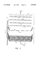
- FIG. 2 is a diagrammatic cross section view, partially exploded, illustrating the construction of a plurality of bipolar cells utilized in the battery of FIG. 1.
- FIG. 1 illustrates a bipolar rechargeable battery 20 which may be, for example, of the bipolar nickel hydrogen variety.
- a vessel for the battery is defined by a central cylinder 22 which may be coated with a Teflon® liner 24, shown in FIG. 2, and opposed, possibly spherical, end caps 26, 28 which may be drawn together into firm engagement with opposed end rims of the central cylinder by means of a suitable fastener.
- the central cylinder 22 and the end caps 26, 28 provide an inner surface 32 defining an interior region 34 for bulk gas storage as will be described. With this construction, the battery 20 is capable of withstanding such pressures as are generated by the contained gases.
- Each cell 36 contains a metered predetermined quantity of electrolyte and includes a metallic bipolar cup of dish 38 having a base 40 and an integral upstanding upwardly and outwardly tapered side wall 42 encompassing the base.
- the upstanding side wall is of truncated conical shape diverging with increased distance from the base.
- a hydrophobic insulating and sealing coating 44 covers the interior and exterior surfaces of the tapered wall 42 of each dish 38, including the peripheral rim thereof, so as to insulate the wall 42 of each of the bipolar metallic dishes 38 from each other when the cell 36 including the dishes 38 are nested into contact with each other to form the battery 20.
- the metallic bipolar cup 38 may be fabricated from a variety of materials including nickel, aluminum plated with nickel, stainless steel, metallic coated graphite composite and titanium.
- a porous condensed phase positive electrode 46 is positioned proximate the base of each cup 38.
- the condensed phase electrodes used for the purposes of the present invention are typically 84% porous 0.1 cm thick sintered nickel supported on a nickel screen and electrochemically loaded to between 1.0 and 2.5 g/cm 3 of void volume with active Ni(OH) 2 .
- This is a standard aerospace positive electrode although it is understood that a variety of nickel positive electrodes could be employed.
- a sintered nickel electrode without a support screen would be preferred as the screen is not needed for current conduction in a bipolar battery.
- a gas electrode 48 including a condensed current collector for a gaseous active material.
- the gas electrode is typically platinum powder of platinized carbon powder bonded with Teflon® and supported on carbon cloth or expanded metal.
- the gas electrode must be conductive through its thickness and, to this end, has no hydrophobic wet proofing porous Teflon® layer. Backside hydrophobicity is still required in order that the electrolyte not flood and block a gas screen 50, to be described. This is achieved by the vendor of the gas electrode 48 using a proprietary hydrophobic carbon coating on the gas side of the electrode.
- the gas electrode 48 is a current collector for a gaseous active material and is sized to fittingly engage the side wall 42 such that any gas generated at the condensed phase electrode 46 must pass through the gas electrode to escape the cell 36 to thereby recombine the generated gas with the active material gas within the cell.
- a porous dielectric separator 50 Intermediate the gas electrode 48 and the condensed phase electrode 46 is a porous dielectric separator 50.
- One form of the separator for purposes of the invention is ZrO 2 woven cloth approximately 80% porous and 0.05 cm thick. However, other suitable materials could be used to achieve a similar result.
- the separator acts to electrically insulate the opposing electrodes but allows ionic conduction between the electrodes via the liquid electrolyte which fills the pores of the separator.
- the upstanding side walls 42 of adjacent cells 36 are oriented such that they mutually define a gap 52, shown in FIG. 2, enabling gas communication between the adjacent cells and between each of the cells and the interior bulk gas region 34 within the battery 20.
- an insulating liner 24 is provided on the inner surface of the vessel for assuring its fluid integrity.
- the gas screen 54 may be any porous conductive inert material such as nickel screen, porous nickel felt, nickel coated plastic screen, and the like. It serves the purpose of allowing shared H 2 access to the entire face of the gas electrode and provides electrical conductivity between adjacent cells.
- Each cell is assembled by laying the components up in the metallic bipolar cup in the order illustrated in FIGS. 1 and 2. Once the condensed phase electrode 46 and dielectric separator 50 are in place, sufficient electrolyte is introduced to the cup to fill between 60% and 100% of the porous volume of the condensed phase electrode and separator.
- the electrolyte for this battery is typically a mixture of KOH and LiOH in water with weight percent between 15% and 45% of KOH and 0% and 20% of LiOH.
- assembly is completed by laying the gas electrode 48 and gas screen 54 in the metallic cup. Battery assembly consists of repetitively stacking cells in series to achieve the desired cell count and battery voltage.
- the stacked cells are placed in the vessel defined by the central cylinder 22 and end caps 26, 28 which together constitute a pressure vessel, compressed to a predetermined initial low-pressure value up about 5 psi. This low pressure stabilizes the stacked cells and allows the liquid electrolyte into the porous condensed phase electrode 46 and into the porous separator 50.
- the bus leads 56 (negative) and 58 (positive) from the electrodes 60, 40, respectively, are attached to the battery terminals, and the vessel is closed.
- the battery is subjected to about 10 charge--discharge cycles with a starting cycle at about 20-50% of the full normal charge current and gradually increasing the charge of each cycle to a final cycle at full charge current, to cause the expansion of the full absorption of the liquid electrolyte.
- the battery is subjected to elevated assembly pressure above about 20 psi, generally 23 to 25 psi, without any ejection of liquid electrolyte from the cells.
- the essential novelty of the present invention relates to the dual pressure assembly method which causes a major volume of the liquid electrolyte applied to each of the cells to be absorbed within the porous electrode 46 and within the porous separator 50 of each cell by the initial application of a low pressure and the subsequent low current cycling.
- the initial low pressure is preferably up to about 5 psi, most preferably about 3 psi, which low pressure is insufficient to compress the electrode 46 or the separator 50 and exude the electrolyte therefrom or from one cell into adjacent cells.
- the stacked cells are subjected to the conventional high assembly pressure greater than about 20 psi, generally between about 23 and 25 psi, to seat and seal the stacked cells within each other and compress the stack to the required height within the battery vessel or housing.
- the conventional high assembly pressure greater than about 20 psi, generally between about 23 and 25 psi, to seat and seal the stacked cells within each other and compress the stack to the required height within the battery vessel or housing.
Landscapes
- Engineering & Computer Science (AREA)
- Manufacturing & Machinery (AREA)
- Chemical & Material Sciences (AREA)
- Chemical Kinetics & Catalysis (AREA)
- Electrochemistry (AREA)
- General Chemical & Material Sciences (AREA)
- Secondary Cells (AREA)
- Hybrid Cells (AREA)
- Battery Electrode And Active Subsutance (AREA)
Abstract
Description
Claims (6)
Priority Applications (3)
| Application Number | Priority Date | Filing Date | Title |
|---|---|---|---|
| US08/904,492 US5752987A (en) | 1997-08-01 | 1997-08-01 | Method for producing improved electrolyte-retention bipolar cells and batteries |
| FR9809418A FR2766971A1 (en) | 1997-08-01 | 1998-07-23 | PROCESS FOR MANUFACTURING BATTERIES AND BIPOLAR BATTERIES WITH IMPROVED ELECTROLYTE RETENTION |
| JP10217131A JPH11121030A (en) | 1997-08-01 | 1998-07-31 | Manufacture of bipolar cell and battery holding improved electrolyte |
Applications Claiming Priority (1)
| Application Number | Priority Date | Filing Date | Title |
|---|---|---|---|
| US08/904,492 US5752987A (en) | 1997-08-01 | 1997-08-01 | Method for producing improved electrolyte-retention bipolar cells and batteries |
Publications (1)
| Publication Number | Publication Date |
|---|---|
| US5752987A true US5752987A (en) | 1998-05-19 |
Family
ID=25419252
Family Applications (1)
| Application Number | Title | Priority Date | Filing Date |
|---|---|---|---|
| US08/904,492 Expired - Fee Related US5752987A (en) | 1997-08-01 | 1997-08-01 | Method for producing improved electrolyte-retention bipolar cells and batteries |
Country Status (3)
| Country | Link |
|---|---|
| US (1) | US5752987A (en) |
| JP (1) | JPH11121030A (en) |
| FR (1) | FR2766971A1 (en) |
Cited By (9)
| Publication number | Priority date | Publication date | Assignee | Title |
|---|---|---|---|---|
| US5858574A (en) * | 1997-07-25 | 1999-01-12 | Space Systems/Loral, Inc. | Cells and gas depolarized batteries and method for producing same |
| US20060292443A1 (en) * | 2005-05-03 | 2006-12-28 | Randy Ogg | Bi-polar rechargeable electrochemical battery |
| US20090023061A1 (en) * | 2007-02-12 | 2009-01-22 | Randy Ogg | Stacked constructions for electrochemical batteries |
| US20090142655A1 (en) * | 2007-10-26 | 2009-06-04 | G4 Synergetics, Inc. | Dish shaped and pressure equalizing electrodes for electrochemical batteries |
| US20100203384A1 (en) * | 2009-01-27 | 2010-08-12 | G4 Synergetics, Inc. | Electrode folds for energy storage devices |
| US20100304191A1 (en) * | 2009-04-24 | 2010-12-02 | G4 Synergetics, Inc. | Energy storage devices having cells electrically coupled in series and in parallel |
| CN106033823A (en) * | 2015-03-11 | 2016-10-19 | 北京好风光储能技术有限公司 | High voltage power battery with controllable volume of injected liquid and preparation method thereof |
| US20240072338A1 (en) * | 2022-08-29 | 2024-02-29 | EnerVenue Inc. | Nickel-Hydrogen Battery Configurations for Grid-Scale Energy Storage |
| US12107249B2 (en) * | 2022-08-29 | 2024-10-01 | EnerVenue Inc. | Nickel-hydrogen battery configurations for grid-scale energy storage |
Families Citing this family (2)
| Publication number | Priority date | Publication date | Assignee | Title |
|---|---|---|---|---|
| KR100733894B1 (en) | 2006-02-13 | 2007-07-02 | 국방과학연구소 | Reserve battery |
| JP5626872B2 (en) * | 2010-09-16 | 2014-11-19 | 学校法人同志社 | Hydrogen / air secondary battery |
Citations (2)
| Publication number | Priority date | Publication date | Assignee | Title |
|---|---|---|---|---|
| US4872957A (en) * | 1988-07-20 | 1989-10-10 | H-D Tech Inc. | Electrochemical cell having dual purpose electrode |
| US5652073A (en) * | 1996-04-03 | 1997-07-29 | Space Systems/Loral, Inc. | Bipolar cell design for a gas depolarized battery |
-
1997
- 1997-08-01 US US08/904,492 patent/US5752987A/en not_active Expired - Fee Related
-
1998
- 1998-07-23 FR FR9809418A patent/FR2766971A1/en not_active Withdrawn
- 1998-07-31 JP JP10217131A patent/JPH11121030A/en active Pending
Patent Citations (2)
| Publication number | Priority date | Publication date | Assignee | Title |
|---|---|---|---|---|
| US4872957A (en) * | 1988-07-20 | 1989-10-10 | H-D Tech Inc. | Electrochemical cell having dual purpose electrode |
| US5652073A (en) * | 1996-04-03 | 1997-07-29 | Space Systems/Loral, Inc. | Bipolar cell design for a gas depolarized battery |
Cited By (14)
| Publication number | Priority date | Publication date | Assignee | Title |
|---|---|---|---|---|
| US5858574A (en) * | 1997-07-25 | 1999-01-12 | Space Systems/Loral, Inc. | Cells and gas depolarized batteries and method for producing same |
| US7794877B2 (en) | 2005-05-03 | 2010-09-14 | Randy Ogg | Bi-polar rechargeable electrochemical battery |
| US20060292443A1 (en) * | 2005-05-03 | 2006-12-28 | Randy Ogg | Bi-polar rechargeable electrochemical battery |
| US20100304216A1 (en) * | 2005-05-03 | 2010-12-02 | G4 Synergetics, Inc. | Bi-polar rechargeable electrochemical battery |
| US20090023061A1 (en) * | 2007-02-12 | 2009-01-22 | Randy Ogg | Stacked constructions for electrochemical batteries |
| US20090142655A1 (en) * | 2007-10-26 | 2009-06-04 | G4 Synergetics, Inc. | Dish shaped and pressure equalizing electrodes for electrochemical batteries |
| US8632901B2 (en) | 2007-10-26 | 2014-01-21 | G4 Synergetics, Inc. | Dish shaped and pressure equalizing electrodes for electrochemical batteries |
| US20100203384A1 (en) * | 2009-01-27 | 2010-08-12 | G4 Synergetics, Inc. | Electrode folds for energy storage devices |
| US8859132B2 (en) | 2009-01-27 | 2014-10-14 | G4 Synergetics, Inc. | Variable volume containment for energy storage devices |
| US20100304191A1 (en) * | 2009-04-24 | 2010-12-02 | G4 Synergetics, Inc. | Energy storage devices having cells electrically coupled in series and in parallel |
| CN106033823A (en) * | 2015-03-11 | 2016-10-19 | 北京好风光储能技术有限公司 | High voltage power battery with controllable volume of injected liquid and preparation method thereof |
| CN106033823B (en) * | 2015-03-11 | 2018-11-13 | 北京好风光储能技术有限公司 | A kind of high voltage power battery and preparation method thereof that reservoir quantity is controllable |
| US20240072338A1 (en) * | 2022-08-29 | 2024-02-29 | EnerVenue Inc. | Nickel-Hydrogen Battery Configurations for Grid-Scale Energy Storage |
| US12107249B2 (en) * | 2022-08-29 | 2024-10-01 | EnerVenue Inc. | Nickel-hydrogen battery configurations for grid-scale energy storage |
Also Published As
| Publication number | Publication date |
|---|---|
| JPH11121030A (en) | 1999-04-30 |
| FR2766971A1 (en) | 1999-02-05 |
Similar Documents
| Publication | Publication Date | Title |
|---|---|---|
| Chakkaravarthy et al. | Zinc—air alkaline batteries—A review | |
| US4159367A (en) | Hydrogen electrochemical cell and rechargeable metal-hydrogen battery | |
| US4054726A (en) | Galvanic primary element with air electrode | |
| US7006346B2 (en) | Positive electrode of an electric double layer capacitor | |
| US3891462A (en) | Galvanic cell structure | |
| EP0697746B1 (en) | Sealed zinc secondary battery and zinc electrode therefor | |
| US6806001B1 (en) | Battery in bipolar stacked configuration and method for the production thereof | |
| US3990910A (en) | Nickel-hydrogen battery | |
| JPH09510576A (en) | Lead battery | |
| US4994334A (en) | Sealed alkaline storage battery and method of producing negative electrode thereof | |
| US5752987A (en) | Method for producing improved electrolyte-retention bipolar cells and batteries | |
| US5652073A (en) | Bipolar cell design for a gas depolarized battery | |
| US6670077B1 (en) | Impregnated separator for electrochemical cell and method of making same | |
| EP1232532B1 (en) | Electrochemical cell constructions and methods of making the same | |
| US4450211A (en) | Electrochemical generator comprising a thin gas electrode | |
| US5821009A (en) | Fault tolerant bipolar gas electrode design for a rechargeable battery | |
| JP2512019B2 (en) | Electrochemical battery | |
| US5882817A (en) | Battery cell design for a bipolar rechargeable battery | |
| US4174565A (en) | Method of precharging rechargeable metal oxide-hydrogen cells | |
| CA2318994A1 (en) | Prismatic electrochemical cell | |
| US20010016282A1 (en) | Gastight-sealed alkaline storage battery in the form of a button cell | |
| US3836398A (en) | Electrochemical generators of the metal-air or metal-oxygen type | |
| US5789097A (en) | Gas-tight maintenance-free cell or battery | |
| US5858574A (en) | Cells and gas depolarized batteries and method for producing same | |
| JP4366541B2 (en) | Oxyhalide-lithium battery |
Legal Events
| Date | Code | Title | Description |
|---|---|---|---|
| AS | Assignment |
Owner name: SPACE SYSTEMS/LORAL, INC., CALIFORNIA Free format text: ASSIGNMENT OF ASSIGNORS INTEREST;ASSIGNOR:YANG, THOMAS;REEL/FRAME:008735/0389 Effective date: 19970729 |
|
| FEPP | Fee payment procedure |
Free format text: PAYOR NUMBER ASSIGNED (ORIGINAL EVENT CODE: ASPN); ENTITY STATUS OF PATENT OWNER: LARGE ENTITY |
|
| REMI | Maintenance fee reminder mailed | ||
| LAPS | Lapse for failure to pay maintenance fees | ||
| STCH | Information on status: patent discontinuation |
Free format text: PATENT EXPIRED DUE TO NONPAYMENT OF MAINTENANCE FEES UNDER 37 CFR 1.362 |
|
| FP | Lapsed due to failure to pay maintenance fee |
Effective date: 20020519 |
|
| AS | Assignment |
Owner name: ROYAL BANK OF CANADA, AS THE COLLATERAL AGENT, CANADA Free format text: SECURITY INTEREST;ASSIGNORS:DIGITALGLOBE, INC.;MACDONALD, DETTWILER AND ASSOCIATES LTD.;MACDONALD, DETTWILER AND ASSOCIATES CORPORATION;AND OTHERS;REEL/FRAME:044167/0396 Effective date: 20171005 Owner name: ROYAL BANK OF CANADA, AS THE COLLATERAL AGENT, CAN Free format text: SECURITY INTEREST;ASSIGNORS:DIGITALGLOBE, INC.;MACDONALD, DETTWILER AND ASSOCIATES LTD.;MACDONALD, DETTWILER AND ASSOCIATES CORPORATION;AND OTHERS;REEL/FRAME:044167/0396 Effective date: 20171005 |
|
| AS | Assignment |
Owner name: MAXAR SPACE LLC, CALIFORNIA Free format text: TERMINATION AND RELEASE OF SECURITY INTEREST IN PATENTS AND TRADEMARKS - RELEASE OF REEL/FRAME 044167/0396;ASSIGNOR:ROYAL BANK OF CANADA, AS AGENT;REEL/FRAME:063543/0001 Effective date: 20230503 Owner name: MAXAR INTELLIGENCE INC., COLORADO Free format text: TERMINATION AND RELEASE OF SECURITY INTEREST IN PATENTS AND TRADEMARKS - RELEASE OF REEL/FRAME 044167/0396;ASSIGNOR:ROYAL BANK OF CANADA, AS AGENT;REEL/FRAME:063543/0001 Effective date: 20230503 |