US5745954A - Playyard hinge - Google Patents
Playyard hinge Download PDFInfo
- Publication number
- US5745954A US5745954A US08/736,742 US73674296A US5745954A US 5745954 A US5745954 A US 5745954A US 73674296 A US73674296 A US 73674296A US 5745954 A US5745954 A US 5745954A
- Authority
- US
- United States
- Prior art keywords
- button
- saddle
- plate
- rail
- orientation
- Prior art date
- Legal status (The legal status is an assumption and is not a legal conclusion. Google has not performed a legal analysis and makes no representation as to the accuracy of the status listed.)
- Expired - Fee Related
Links
Images


Classifications
-
- A—HUMAN NECESSITIES
- A47—FURNITURE; DOMESTIC ARTICLES OR APPLIANCES; COFFEE MILLS; SPICE MILLS; SUCTION CLEANERS IN GENERAL
- A47D—FURNITURE SPECIALLY ADAPTED FOR CHILDREN
- A47D13/00—Other nursery furniture
- A47D13/06—Children's play- pens
- A47D13/061—Children's play- pens foldable
- A47D13/063—Children's play- pens foldable with soft walls
-
- Y—GENERAL TAGGING OF NEW TECHNOLOGICAL DEVELOPMENTS; GENERAL TAGGING OF CROSS-SECTIONAL TECHNOLOGIES SPANNING OVER SEVERAL SECTIONS OF THE IPC; TECHNICAL SUBJECTS COVERED BY FORMER USPC CROSS-REFERENCE ART COLLECTIONS [XRACs] AND DIGESTS
- Y10—TECHNICAL SUBJECTS COVERED BY FORMER USPC
- Y10T—TECHNICAL SUBJECTS COVERED BY FORMER US CLASSIFICATION
- Y10T403/00—Joints and connections
- Y10T403/32—Articulated members
- Y10T403/32254—Lockable at fixed position
- Y10T403/32262—At selected angle
- Y10T403/32319—At selected angle including pivot stud
- Y10T403/32409—Members locked in axial alignment
Definitions
- the present invention relates to a hinge and, more particularly, to a playyard having a hinge adapted to safely and conveniently convert the playyard between a deployed orientation and a collapsed orientation.
- playyards for receiving and supporting children are well known. Further, playyards with foldable capabilities are also well known. Such foldable playyards typically have hinges for converting the playyard between an erect deployed orientation and a collapsed orientation for transportation and storage.
- hinges One key element to allow playyards to be retained in one orientation or another are hinges. Such hinges, however, must be made safe for the child and convenient for the health care provider. All known hinges suffer from one defect or the other.
- the present invention achieves its intended purposes, objects and advantages over the prior art through a new, useful and unobvious combination of components elements, through the use of a minimum number of functioning parts, at a reasonable cost to manufacture, and through the utilization of only readily available and conventional materials.
- the present invention relates to a new and improved hinge positioned at the intermediate extents of the adjacent rail components to hold such components in an aligned orientation
- a saddle with a central button aperture, interior plate apertures and exterior end apertures with associated rail pins for pivotally coupling the saddle and the adjacent interior ends of associated rail components
- a pair of locking plates each with a plate pin coupling the upper end of each plate to a plate aperture of the saddle, each plate having an opening extending therethrough the plates urged away from each other
- a liftable button with an elongated slot and with an associated button pin for slidably coupling the button to the saddle, the saddle having inclined bearing surfaces on their edges and an inwardly facing projection located at the adjacent interior edge of each adjacent rod segment, each projection having an upper curved surface and a lower planar surface receivable by the bearing opening.
- Another object of the invention to provide for the convenient deployment and collapse of a playyard with maximum safety.
- the invention essentially comprises a playyard hinge.
- the present invention includes a playyard of the type having a frame with an upper rail assembly positionable in a horizontal orientation when in a deployed orientation and formed of two side rails and two end rails with each of the rails being formed of two rail components having interior ends and exterior ends, the interior ends being pivotally coupled with respect to each other for movement between the deployed orientation wherein the rails are horizontally disposed in a common plane and a collapsed orientation wherein the rails are vertically disposed and parallel, the frame also including a lower rail assembly positionable in a horizontal orientation beneath the upper rail assembly when in a deployed orientation, the frame also including four vertically extending corner rails pivotally coupling the upper rail assembly and the lower rail assembly, the playyard also having fabric components above the lower frame assembly and between the corner rails: a hinge positioned at the intermediate extents of the end rails and side rails to allow movement of the associated rail components between the horizontal orientation and each hinge including: a saddle in a generally inverted U-shaped configuration with a central button aperture, interior plate apertures and exterior end apertures
- FIG. 1 is a perspective illustration of a playyard constructed in accordance with the principles of the present invention.
- FIG. 2 is a perspective showing similar to FIG. 1 but with the fabric enclosure removed to show the frame only.
- FIG. 3 is an enlarged perspective illustration of the hinge assembly shown in the prior figures.
- FIG. 4 is a side elevational view, partly in cross-section of the hinge shown in FIG. 3.
- FIG. 5 is a view similar to FIG. 4 but illustrating the hinge in the collapsed orientation.
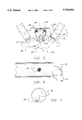
- FIG. 6 is a cross-section view of one of the interior ends of an end rail shown in FIGS. 4 and 5.
- FIG. 7 is an end elevational view of the rail section shown in FIG. 6.
- FIGS. 8 and 9 are enlarged side and end elevational views of the button shown in FIGS. 4 and 5.
- FIGS. 10 and 11 are enlarged end side elevational views of a hinge plate shown in FIGS. 4 and 5.
- FIG. 12 is a perspective illustration of the locking plate shown in FIGS. 10 and 11.
- FIG. 13 is a perspective illustration of tone of the springs for biassing the locking plates to the position of FIG. 5.
- the present invention relates to a playyard with a improved hinge construction.
- the present invention includes a frame structure to which fabric panels are secured.
- the upper rail assemblies each are composed of rail sections having interior ends safely but readily movable between a deployed and collapsed orientation.
- the present invention is a playyard 10. It is of a type having a supporting frame 12.
- the frame has an upper rectangular rail assembly 14. Such rail assembly is positionable in a horizontal orientation as shown in FIGS. 1 and 2. Such orientation is for when the playyard is in a operative or deployed orientation.
- the frame assembly rectangular in the primary embodiment, is provided with two longer side rails 16 and two shorter end rails 18.
- the rails in an alternate embodiment, are all of equal length to form a square playyard.
- Each of the rails, whether the side rails or the end rails, is formed to include two rail components 20. Each rail component has a interior end 22 and an exterior end 24.
- the interior ends of the rails are pivotally coupled with respect to each other through a hinge assembly to be 100 later described.
- Such hinge of the hinge assemblies allow movement between the deployed orientation as shown in FIG. 1 wherein the rails are horizontally disposed in a common plane with the rail components being in axial alignment one with respect to another and a collapsed orientation wherein the rails are all essentially disposed vertically and parallel with respect to each other. Note FIG. 5.
- the frame also includes a lower rail assembly 26.
- the lower rail assembly 28 is positionable in a horizontal orientation. Note FIG. 2. Such orientation is at a location beneath the upper rail assembly when it is deployed.
- the frame also includes four vertically extending corner rails 30.
- Such rails are pivotally coupled at their upper ends through fixed upper corner brackets 32 to their upper rail assemblies and at their lower ends through fixed lower corner brackets or feet 34 to the lower rail assemblies.
- Upper corner brackets and lower corner brackets affect the coupling of the vertical rails to the upper and lower rail assemblies in the conventional manner. Further details of the lower rail assembly may be had by reference to U.S. Pat. No. 5,381,570 to Top Fortune. The subject matter of such patent is incorporated herein by reference.
- fabric components include a lower panel 36 positioned above the lower rail assembly. Also included as part of the component assembly are side panels 38. Such side panels are located between the upper and lower rail assemblies and between the vertical corner rails.
- the unique feature of the present invention is principally in the hinge 100.
- the function of the hinge is to allow safe and convenient movement of the associated rail components between a horizontal orientation and the collapsed position.
- Each hinge includes as its major component a saddle 40.
- the saddle is a rigid member in a generally inverted U-shaped configuration.
- Each hinge is provided with a central button aperture 42 as well as interior plate apertures 44 and exterior rail apertures 46.
- the rail apertures are provided with rail pins 48.
- the rail pins extend through associated apertures in the adjacent ends of the rail components for pivotally coupling the saddle and the adjacent interior ends of the associated rail components.
- a pair of normally vertically oriented locking plates 50 are also coupled to the saddles.
- Each locking plate includes a curved upper portion with a central aperture 52 and a plate pin 54 coupling the upper end of each plate to a plate aperture of the saddle.
- Each plate is also formed with an enlarged opening 56. The opening extends therethrough and is adapted to cooperate with the rail components as will be later described.
- Each opening has a lower bearing surface 58.
- springs, preferably coil springs 60 are located around the plate pins 54 with their central extents in contact with the upper horizontal portion of the saddle at their upper axially exterior ends and in contact with the lateral extents of the plates at their lower central extents. This tends to urge the plates away from each other toward a vertical orientation as shown in FIG. 4 for locking purposes.
- Each such liftable button one for each saddle and hinge, has a slot 64 through a centrally extent thereof.
- the slot is vertically oriented with a button pin 66 extending therethrough and coupled to the lock apertures of the saddle. This will allow for the sliding upwardly of the button with respect to the saddle.
- the button is also formed to have inclined bearing surfaces 68. Such bearing surfaces are at the upper exterior edges of the button and are adapted, when the button is lifted, to contact the lower inturned ends of the plates and move them toward each other when removing the coupling effect between the rail components achieved by the locking plates.
- the lower surface 70 of the button is adapted to be contacted by a user and squeezed upwardly against the upper extent of the saddle when orienting the hinge to the collapsed orientation. Such lower surface 70 is formed with undulations 63 for receiving a users fingers.
- each rail Located within apertures of each rail is an inwardly facing projection 72.
- Such projections are located at the interior edge 74 of each rod segment.
- Each projection has an upper surface adapted to contact the lower edge of the locking plates and push them inwardly when moving toward the deployed orientation.
- Each projection has a lower planar surface 76.
- the lower planar surface is provided with a notch 78.
- Such notches are adapted to receive the bearing surfaces of the plate when the rod segments are in axial alignment at the deployed orientation.
- Such an arrangement of the notch coupled with respect to the bearing surface functions to maintain the playyard deployed.
- upward movement of the button will have its inclined bearing surfaces contact the lower edges of the plates to move the plates inwardly.
- the projections extending through the apertures of the locking plates provide the locking forces to maintain the playyard safely deployed.
- the notches in the projections and the associated bearing surfaces in the locking plates constitute a supplemental and redundant safety feature to further preclude inadvertent collapsing the playyard.
Abstract
Description
Claims (5)
Priority Applications (1)
| Application Number | Priority Date | Filing Date | Title |
|---|---|---|---|
| US08/736,742 US5745954A (en) | 1996-10-25 | 1996-10-25 | Playyard hinge |
Applications Claiming Priority (1)
| Application Number | Priority Date | Filing Date | Title |
|---|---|---|---|
| US08/736,742 US5745954A (en) | 1996-10-25 | 1996-10-25 | Playyard hinge |
Publications (1)
| Publication Number | Publication Date |
|---|---|
| US5745954A true US5745954A (en) | 1998-05-05 |
Family
ID=24961124
Family Applications (1)
| Application Number | Title | Priority Date | Filing Date |
|---|---|---|---|
| US08/736,742 Expired - Fee Related US5745954A (en) | 1996-10-25 | 1996-10-25 | Playyard hinge |
Country Status (1)
| Country | Link |
|---|---|
| US (1) | US5745954A (en) |
Cited By (44)
| Publication number | Priority date | Publication date | Assignee | Title |
|---|---|---|---|---|
| US5857229A (en) * | 1997-09-11 | 1999-01-12 | Magnani, Jr.; Tom J. | Playyard hinge |
| FR2794009A1 (en) * | 1999-05-24 | 2000-12-01 | Pao Hsien Cheng | Hinged joint for infant cot frame has two side plates and locking plate with support cams engaging groove on support block |
| US6202229B1 (en) * | 1999-06-30 | 2001-03-20 | Pao-Hsien Cheng | Joint of a foldable bed for babies |
| US6250837B1 (en) * | 1996-09-10 | 2001-06-26 | Kolcraft Enterprises, Inc. | Rail joint |
| GB2363425A (en) * | 2000-06-15 | 2001-12-19 | Kenny Cheng | Foldable mechanism for a playpen |
| US6421850B1 (en) | 2000-03-06 | 2002-07-23 | Kolcraft Enterprises, Inc. | Play yard having a lower frame with a locking joint |
| US6588033B1 (en) | 2000-05-02 | 2003-07-08 | Kolcraft Enterprises, Inc. | Foldable bassinet with suspended floor hinge |
| US20030229968A1 (en) * | 2002-06-18 | 2003-12-18 | Shun-Min Chen | Playyard latch mechanism |
| AU769609B2 (en) * | 1999-08-02 | 2004-01-29 | Top Fortune Ltd. | Frame of a foldable baby bed |
| US20050147463A1 (en) * | 2004-01-06 | 2005-07-07 | Shun-Min Chen | Coupling device for a foldable frame |
| US20060021136A1 (en) * | 2004-05-08 | 2006-02-02 | Ying-Hsiung Cheng | Joint of a foldable bed for babies |
| US20070017025A1 (en) * | 2005-07-22 | 2007-01-25 | Baby Trend, Inc. | Folding play yard |
| US20070079441A1 (en) * | 2005-10-11 | 2007-04-12 | Owen Chen | Foldable articulation for playpen |
| US20070163041A1 (en) * | 2006-01-18 | 2007-07-19 | Link Treasure Limited | Joint structure for collapsible play yard |
| US20070186344A1 (en) * | 2006-01-13 | 2007-08-16 | Pao-Hsien Cheng | Structure of a moving joint of a folding baby bed with meshes |
| US20070245287A1 (en) * | 2004-06-30 | 2007-10-18 | Andre Rohe | Method and apparatus for identifying connections between configurable nodes in a configurable integrated circuit |
| US20080127412A1 (en) * | 2006-11-30 | 2008-06-05 | Brian Pleiman | Portable infant playyard |
| US20090077740A1 (en) * | 2007-09-25 | 2009-03-26 | Kids Ii, Inc. | Support for an inclinable bassinet assembly |
| US20090133190A1 (en) * | 2007-11-26 | 2009-05-28 | Hong-Bo Chen | Playard |
| US20090260184A1 (en) * | 2008-04-21 | 2009-10-22 | Excellerate Enterrise Co., Ltd. | Coupling device for a baby crib frame structure |
| US7614097B1 (en) * | 2008-06-03 | 2009-11-10 | Ying-Hsiung Cheng | Structure of a foldable mechanism of a baby mesh bed |
| US20100218311A1 (en) * | 2009-02-27 | 2010-09-02 | Graco Children's Products Inc. | Playard Top Rail and Latch Mechanism |
| US20110176859A1 (en) * | 2010-01-20 | 2011-07-21 | Shao-Hua Chu | Speedy Pivoting-and-Fixing Device for Foldable Structure |
| US20110229251A1 (en) * | 2010-03-19 | 2011-09-22 | Lerado (Zhong Shan) Industrial Co., Ltd | Joint structure with a stable unlocked state for a foldable playpen |
| US8172239B1 (en) * | 2009-07-01 | 2012-05-08 | Cherylene Boyd | Collapsible shopping cart system |
| US20130074257A1 (en) * | 2011-09-07 | 2013-03-28 | Kids Ii, Inc. | Locking hinge mechanism for a collapsible play yard frame |
| EP2837309A1 (en) * | 2013-08-13 | 2015-02-18 | Wonderland Nurserygoods Company Limited | Infant playpen capable of receiving the installation of multiple removable accessories |
| CN105411277A (en) * | 2015-11-27 | 2016-03-23 | 安徽酷豆丁儿童用品有限公司 | Folding mechanism of child's game bed frame |
| US10463170B2 (en) | 2015-09-09 | 2019-11-05 | Kids Ii, Inc. | Collapsible play yard |
| USD866995S1 (en) | 2016-09-08 | 2019-11-19 | Kids2, Inc. | Play yard |
| US10806246B1 (en) * | 2019-09-30 | 2020-10-20 | Inno-Sports Co., Ltd. | Retainers and foldable table having same |
| US11382416B2 (en) | 2019-12-09 | 2022-07-12 | Inno-Sports Co., Ltd. | Stress-dispersing structure, frame and table having same |
| US11523681B2 (en) | 2019-12-09 | 2022-12-13 | Inno-Sports Co., Ltd. | Frame and table having structure for reducing vibration |
| US11523683B2 (en) | 2020-04-23 | 2022-12-13 | Inno-Sports Co., Ltd. | Blow-molded unitary structure with enhanced strength |
| US11524812B2 (en) | 2020-04-28 | 2022-12-13 | Inno-Sports Co., Ltd. | Blow-molded unitary structure with enhanced strength |
| US11564494B2 (en) | 2020-07-27 | 2023-01-31 | Inno-Sports Co., Ltd. | Blow-molded unitary structure with enhanced strength |
| US11564492B2 (en) | 2020-07-27 | 2023-01-31 | Inno-Sports Co., Ltd. | Blow-molded unitary structure with enhanced strength |
| US11578832B2 (en) | 2020-01-20 | 2023-02-14 | Inno-Sports Co., Ltd. | Compact foldable frame |
| US11678740B2 (en) | 2021-03-16 | 2023-06-20 | Inno-Sports Co., Ltd. | Frame with minimized thickness when folded |
| US11686429B2 (en) | 2020-01-20 | 2023-06-27 | Inno-Sports Co., Ltd. | Supporting assembly and frame having same |
| US11690444B2 (en) | 2021-02-04 | 2023-07-04 | Inno-Sports Co., Ltd. | Foldable frame and table having same |
| US11712109B2 (en) | 2021-03-16 | 2023-08-01 | Inno-Sports Co., Ltd. | Retainer and frame having same |
| US11882930B2 (en) | 2021-02-04 | 2024-01-30 | Inno-Sports Co., Ltd. | Foldable frame and table having same |
| US11937695B2 (en) | 2021-11-01 | 2024-03-26 | Inno-Sports Co., Ltd. | Height-adjustable folding table |
Citations (6)
| Publication number | Priority date | Publication date | Assignee | Title |
|---|---|---|---|---|
| US4611945A (en) * | 1985-06-07 | 1986-09-16 | Diego Dennis F | Articulating joint for folding tubular sections |
| US4811437A (en) * | 1987-06-26 | 1989-03-14 | Graco Metal Products, Inc. | Foldable playyard |
| US5293656A (en) * | 1992-12-21 | 1994-03-15 | Chan Te Erh | Foldable frame assembly for a children's playpen |
| US5353451A (en) * | 1993-06-03 | 1994-10-11 | Hsiung Yu Kuang | Playpen frame structure |
| US5483710A (en) * | 1994-01-11 | 1996-01-16 | Chan; Te-Erh | Joint for the top rails of a foldable baby crib |
| US5530977A (en) * | 1994-08-25 | 1996-07-02 | Wang; Kun | Control device for folding and expanding armrail of a playpen |
-
1996
- 1996-10-25 US US08/736,742 patent/US5745954A/en not_active Expired - Fee Related
Patent Citations (6)
| Publication number | Priority date | Publication date | Assignee | Title |
|---|---|---|---|---|
| US4611945A (en) * | 1985-06-07 | 1986-09-16 | Diego Dennis F | Articulating joint for folding tubular sections |
| US4811437A (en) * | 1987-06-26 | 1989-03-14 | Graco Metal Products, Inc. | Foldable playyard |
| US5293656A (en) * | 1992-12-21 | 1994-03-15 | Chan Te Erh | Foldable frame assembly for a children's playpen |
| US5353451A (en) * | 1993-06-03 | 1994-10-11 | Hsiung Yu Kuang | Playpen frame structure |
| US5483710A (en) * | 1994-01-11 | 1996-01-16 | Chan; Te-Erh | Joint for the top rails of a foldable baby crib |
| US5530977A (en) * | 1994-08-25 | 1996-07-02 | Wang; Kun | Control device for folding and expanding armrail of a playpen |
Cited By (66)
| Publication number | Priority date | Publication date | Assignee | Title |
|---|---|---|---|---|
| US6250837B1 (en) * | 1996-09-10 | 2001-06-26 | Kolcraft Enterprises, Inc. | Rail joint |
| US5857229A (en) * | 1997-09-11 | 1999-01-12 | Magnani, Jr.; Tom J. | Playyard hinge |
| FR2794009A1 (en) * | 1999-05-24 | 2000-12-01 | Pao Hsien Cheng | Hinged joint for infant cot frame has two side plates and locking plate with support cams engaging groove on support block |
| US6202229B1 (en) * | 1999-06-30 | 2001-03-20 | Pao-Hsien Cheng | Joint of a foldable bed for babies |
| AU769609B2 (en) * | 1999-08-02 | 2004-01-29 | Top Fortune Ltd. | Frame of a foldable baby bed |
| US6421850B1 (en) | 2000-03-06 | 2002-07-23 | Kolcraft Enterprises, Inc. | Play yard having a lower frame with a locking joint |
| US6588033B1 (en) | 2000-05-02 | 2003-07-08 | Kolcraft Enterprises, Inc. | Foldable bassinet with suspended floor hinge |
| GB2363425A (en) * | 2000-06-15 | 2001-12-19 | Kenny Cheng | Foldable mechanism for a playpen |
| GB2363425B (en) * | 2000-06-15 | 2004-07-14 | Kenny Cheng | Foldable mechanism for playyard |
| US6915545B2 (en) * | 2002-06-18 | 2005-07-12 | Kenny Cheng | Playyard latch mechanism |
| US20030229968A1 (en) * | 2002-06-18 | 2003-12-18 | Shun-Min Chen | Playyard latch mechanism |
| US7108443B2 (en) | 2004-01-06 | 2006-09-19 | Wonderland Nurserygoods Co., Ltd. | Coupling device for a foldable frame |
| US20050147463A1 (en) * | 2004-01-06 | 2005-07-07 | Shun-Min Chen | Coupling device for a foldable frame |
| EP1552775A1 (en) * | 2004-01-06 | 2005-07-13 | Wonderland Nurserygoods Co., Ltd. | Coupling device for a foldable frame |
| US20060021136A1 (en) * | 2004-05-08 | 2006-02-02 | Ying-Hsiung Cheng | Joint of a foldable bed for babies |
| US20070245287A1 (en) * | 2004-06-30 | 2007-10-18 | Andre Rohe | Method and apparatus for identifying connections between configurable nodes in a configurable integrated circuit |
| US20070017025A1 (en) * | 2005-07-22 | 2007-01-25 | Baby Trend, Inc. | Folding play yard |
| US20070079441A1 (en) * | 2005-10-11 | 2007-04-12 | Owen Chen | Foldable articulation for playpen |
| US7380311B2 (en) * | 2005-10-11 | 2008-06-03 | Owen Chen | Foldable articulation for playpen |
| US7284288B2 (en) * | 2006-01-13 | 2007-10-23 | Pao-Hsien Cheng | Structure of a moving joint of a folding baby bed with meshes |
| US20070186344A1 (en) * | 2006-01-13 | 2007-08-16 | Pao-Hsien Cheng | Structure of a moving joint of a folding baby bed with meshes |
| US20070163041A1 (en) * | 2006-01-18 | 2007-07-19 | Link Treasure Limited | Joint structure for collapsible play yard |
| US20080127412A1 (en) * | 2006-11-30 | 2008-06-05 | Brian Pleiman | Portable infant playyard |
| US20090077740A1 (en) * | 2007-09-25 | 2009-03-26 | Kids Ii, Inc. | Support for an inclinable bassinet assembly |
| US20090077775A1 (en) * | 2007-09-25 | 2009-03-26 | Burns Stephen R | Zipper pull tab lock |
| US20090077738A1 (en) * | 2007-09-25 | 2009-03-26 | Kids Ii, Inc. | Redundant support feature for bassinet assembly and play yard combination |
| US8201291B2 (en) | 2007-09-25 | 2012-06-19 | Kids Ii, Inc. | Redundant support feature for bassinet assembly and play yard combination |
| US8141186B2 (en) | 2007-09-25 | 2012-03-27 | Kids Ii, Inc. | Mesh arrangement for bassinet assembly |
| US7882579B2 (en) | 2007-09-25 | 2011-02-08 | Kids Ii, Inc. | Support for an inclinable bassinet assembly |
| US7739759B2 (en) | 2007-09-25 | 2010-06-22 | Kids Ii, Inc. | Play yard and bassinet assembly |
| US7752688B2 (en) * | 2007-11-26 | 2010-07-13 | Excellerate Enterprise Co., Ltd. | Playard |
| US20090133190A1 (en) * | 2007-11-26 | 2009-05-28 | Hong-Bo Chen | Playard |
| US8069533B2 (en) * | 2008-04-21 | 2011-12-06 | Excellerate Enterprise Co., Ltd. | Coupling device for a baby crib frame structure |
| US20090260184A1 (en) * | 2008-04-21 | 2009-10-22 | Excellerate Enterrise Co., Ltd. | Coupling device for a baby crib frame structure |
| US7614097B1 (en) * | 2008-06-03 | 2009-11-10 | Ying-Hsiung Cheng | Structure of a foldable mechanism of a baby mesh bed |
| US20090293194A1 (en) * | 2008-06-03 | 2009-12-03 | Ying-Hsiung Cheng | Structure of a foldable mechanism of a baby mesh bed |
| US20100218311A1 (en) * | 2009-02-27 | 2010-09-02 | Graco Children's Products Inc. | Playard Top Rail and Latch Mechanism |
| US8387178B2 (en) | 2009-02-27 | 2013-03-05 | Graco Children's Products Inc. | Playard top rail and latch mechanism |
| US8172239B1 (en) * | 2009-07-01 | 2012-05-08 | Cherylene Boyd | Collapsible shopping cart system |
| US20110176859A1 (en) * | 2010-01-20 | 2011-07-21 | Shao-Hua Chu | Speedy Pivoting-and-Fixing Device for Foldable Structure |
| US20110229251A1 (en) * | 2010-03-19 | 2011-09-22 | Lerado (Zhong Shan) Industrial Co., Ltd | Joint structure with a stable unlocked state for a foldable playpen |
| US9103368B2 (en) * | 2011-09-07 | 2015-08-11 | Kids Ii, Inc. | Locking hinge mechanism for a collapsible play yard frame |
| US20130074257A1 (en) * | 2011-09-07 | 2013-03-28 | Kids Ii, Inc. | Locking hinge mechanism for a collapsible play yard frame |
| CN104367038B (en) * | 2013-08-13 | 2018-09-28 | 明门香港股份有限公司 | The baby's game bed of a variety of accessories can be installed |
| CN104367038A (en) * | 2013-08-13 | 2015-02-25 | 明门香港股份有限公司 | Infant playpen capable of receiving the installation of multiple removable accessories |
| EP2837309A1 (en) * | 2013-08-13 | 2015-02-18 | Wonderland Nurserygoods Company Limited | Infant playpen capable of receiving the installation of multiple removable accessories |
| US9078530B2 (en) | 2013-08-13 | 2015-07-14 | Wonderland Nurserygoods Company Limited | Infant playpen capable of receiving the installation of multiple removable accessories |
| US10463170B2 (en) | 2015-09-09 | 2019-11-05 | Kids Ii, Inc. | Collapsible play yard |
| CN105411277A (en) * | 2015-11-27 | 2016-03-23 | 安徽酷豆丁儿童用品有限公司 | Folding mechanism of child's game bed frame |
| CN105411277B (en) * | 2015-11-27 | 2019-02-15 | 安徽酷豆丁科技发展股份有限公司 | A kind of fold mechanism of child play bed bedstead |
| USD866995S1 (en) | 2016-09-08 | 2019-11-19 | Kids2, Inc. | Play yard |
| US10806246B1 (en) * | 2019-09-30 | 2020-10-20 | Inno-Sports Co., Ltd. | Retainers and foldable table having same |
| US11382416B2 (en) | 2019-12-09 | 2022-07-12 | Inno-Sports Co., Ltd. | Stress-dispersing structure, frame and table having same |
| US11523681B2 (en) | 2019-12-09 | 2022-12-13 | Inno-Sports Co., Ltd. | Frame and table having structure for reducing vibration |
| US11578832B2 (en) | 2020-01-20 | 2023-02-14 | Inno-Sports Co., Ltd. | Compact foldable frame |
| US11686429B2 (en) | 2020-01-20 | 2023-06-27 | Inno-Sports Co., Ltd. | Supporting assembly and frame having same |
| US11523683B2 (en) | 2020-04-23 | 2022-12-13 | Inno-Sports Co., Ltd. | Blow-molded unitary structure with enhanced strength |
| US11524812B2 (en) | 2020-04-28 | 2022-12-13 | Inno-Sports Co., Ltd. | Blow-molded unitary structure with enhanced strength |
| US11564492B2 (en) | 2020-07-27 | 2023-01-31 | Inno-Sports Co., Ltd. | Blow-molded unitary structure with enhanced strength |
| US11564494B2 (en) | 2020-07-27 | 2023-01-31 | Inno-Sports Co., Ltd. | Blow-molded unitary structure with enhanced strength |
| US11937696B2 (en) | 2020-07-27 | 2024-03-26 | Inno-Sports Co., Ltd. | Blow-molded unitary structure with enhanced strength |
| US11690444B2 (en) | 2021-02-04 | 2023-07-04 | Inno-Sports Co., Ltd. | Foldable frame and table having same |
| US11882930B2 (en) | 2021-02-04 | 2024-01-30 | Inno-Sports Co., Ltd. | Foldable frame and table having same |
| US11678740B2 (en) | 2021-03-16 | 2023-06-20 | Inno-Sports Co., Ltd. | Frame with minimized thickness when folded |
| US11712109B2 (en) | 2021-03-16 | 2023-08-01 | Inno-Sports Co., Ltd. | Retainer and frame having same |
| US11937695B2 (en) | 2021-11-01 | 2024-03-26 | Inno-Sports Co., Ltd. | Height-adjustable folding table |
Similar Documents
| Publication | Publication Date | Title |
|---|---|---|
| US5745954A (en) | Playyard hinge | |
| US5857229A (en) | Playyard hinge | |
| US7284288B2 (en) | Structure of a moving joint of a folding baby bed with meshes | |
| US5761755A (en) | Foldable devices for a crib frame assembly | |
| US5781944A (en) | Foldable device for a crib | |
| US6915545B2 (en) | Playyard latch mechanism | |
| US6421850B1 (en) | Play yard having a lower frame with a locking joint | |
| US7614097B1 (en) | Structure of a foldable mechanism of a baby mesh bed | |
| US7434279B2 (en) | Folding device for playpen | |
| US20070209112A1 (en) | Bassinet selectively rockable when mounted upon a support as well as being displaced therefrom | |
| US5803650A (en) | Joint structure of collapsible playpen | |
| US5446931A (en) | Children's playyard | |
| US6385800B1 (en) | Collapsible playyard | |
| US20070204400A1 (en) | Control device of lower frame assembly for a playpen | |
| US6317907B1 (en) | Safety device for a collapsible playpen | |
| US20100192812A1 (en) | Foldable bar table | |
| US5938218A (en) | Walker and rocking horse | |
| US20030154547A1 (en) | Foldable playyard | |
| US6698042B2 (en) | Base of a foldable baby bed | |
| US4703525A (en) | Foldable playpen frame | |
| US5253666A (en) | Umbrella opening and closing device without use of spring latches | |
| US6725475B1 (en) | Foldable mechanism for a base of playyard | |
| KR101292823B1 (en) | Push-button folding table leg | |
| US7174908B2 (en) | Multipurpose net frame | |
| JP4583957B2 (en) | Blind bottom fixing structure |
Legal Events
| Date | Code | Title | Description |
|---|---|---|---|
| AS | Assignment |
Owner name: LISCO, INC., FLORIDA Free format text: ASSIGNMENT OF ASSIGNORS INTEREST;ASSIGNORS:SHOGAN, GREGORY P.;STROUD, DAVID J.;DAWLEY, MARK;REEL/FRAME:008411/0909;SIGNING DATES FROM 19970304 TO 19970305 |
|
| AS | Assignment |
Owner name: BANK OF AMERICA NATIONAL TRUST & SAVINGS ASSOCIATI Free format text: SECURITY AGREEMENT;ASSIGNORS:EVENFLO & SPALDING HOLDINGS CORPORATION;SPALDING & EVENFLO COMPANIES, INC.;EVENFLO COMPANY, INC.;AND OTHERS;REEL/FRAME:009342/0379 Effective date: 19980330 |
|
| AS | Assignment |
Owner name: BANK OF AMERICA NATIONAL TRUST & SAVINGS ASSOCIATI Free format text: SECURITY INTEREST;ASSIGNORS:EVENFLO & SPALDING HOLDINGS CORPORATION;SPALDING & EVENFLO COMPANIES, INC.;EVENFLO COMPANY, INC.;AND OTHERS;REEL/FRAME:009227/0574 Effective date: 19980331 Owner name: BANK OF AMERICA NATIONAL TRUST & SAVINGS ASSOCIATI Free format text: SECURITY AGREEMENT;ASSIGNORS:EVENFLO & SPALDING HOLDINGS CORPORATION;SPALDING & EVENFLO COMPANIES, INC.;EVENFLO COMPANY, INC.;AND OTHERS;REEL/FRAME:009516/0369 Effective date: 19980330 |
|
| AS | Assignment |
Owner name: EVENFLO COMPANY, INC., OHIO Free format text: ASSIGNMENT OF ASSIGNORS INTEREST;ASSIGNOR:LISCO, INC;REEL/FRAME:009827/0269 Effective date: 19980520 |
|
| AS | Assignment |
Owner name: BANK OF AMERICA NATIONAL TRUST AND SAVINGS ASSOCIA Free format text: SECURITY AGREEMENT;ASSIGNORS:EVENFLO COMPANY, INC.;LISCO FEEDING, INC.;LISCO FURNITURE, INC.;REEL/FRAME:009430/0456 Effective date: 19980820 |
|
| FPAY | Fee payment |
Year of fee payment: 4 |
|
| REMI | Maintenance fee reminder mailed | ||
| AS | Assignment |
Owner name: BANK OF AMERICA, N.A., AS ADMINISTRATIVE AGENT, CA Free format text: SECURITY AGREEMENT;ASSIGNORS:EVENFLO COMPANY, INC.;LISCO FEEDING, INC.;LISCO FURNITURE, INC.;REEL/FRAME:013315/0920 Effective date: 20021218 |
|
| AS | Assignment |
Owner name: EVENFLO COMPANY, INC., OHIO Free format text: RELEASE OF PATENT SECURITY;ASSIGNOR:BANK OF AMERICA, N.A.;REEL/FRAME:015127/0606 Effective date: 20040803 Owner name: LISCO FURNITURE, INC., OHIO Free format text: RELEASE OF PATENT SECURITY;ASSIGNOR:BANK OF AMERICA, N.A.;REEL/FRAME:015127/0606 Effective date: 20040803 Owner name: LISCO FEEDING, INC., OHIO Free format text: RELEASE OF PATENT SECURITY;ASSIGNOR:BANK OF AMERICA, N.A.;REEL/FRAME:015127/0606 Effective date: 20040803 |
|
| REMI | Maintenance fee reminder mailed | ||
| LAPS | Lapse for failure to pay maintenance fees | ||
| LAPS | Lapse for failure to pay maintenance fees |
Free format text: PATENT EXPIRED FOR FAILURE TO PAY MAINTENANCE FEES (ORIGINAL EVENT CODE: EXP.); ENTITY STATUS OF PATENT OWNER: LARGE ENTITY |
|
| STCH | Information on status: patent discontinuation |
Free format text: PATENT EXPIRED DUE TO NONPAYMENT OF MAINTENANCE FEES UNDER 37 CFR 1.362 |
|
| FP | Lapsed due to failure to pay maintenance fee |
Effective date: 20060505 |