US574282A - sebastian - Google Patents
sebastian Download PDFInfo
- Publication number
- US574282A US574282A US574282DA US574282A US 574282 A US574282 A US 574282A US 574282D A US574282D A US 574282DA US 574282 A US574282 A US 574282A
- Authority
- US
- United States
- Prior art keywords
- tube
- spindle
- air
- butter
- churn
- Prior art date
- Legal status (The legal status is an assumption and is not a legal conclusion. Google has not performed a legal analysis and makes no representation as to the accuracy of the status listed.)
- Expired - Lifetime
Links
- 239000006071 cream Substances 0.000 description 6
- 235000014121 butter Nutrition 0.000 description 4
- 230000002093 peripheral effect Effects 0.000 description 3
- 238000010276 construction Methods 0.000 description 2
- 230000015572 biosynthetic process Effects 0.000 description 1
- 239000007788 liquid Substances 0.000 description 1
- 235000013336 milk Nutrition 0.000 description 1
- 239000008267 milk Substances 0.000 description 1
- 210000004080 milk Anatomy 0.000 description 1
- 229920000136 polysorbate Polymers 0.000 description 1
Images

Classifications
-
- B—PERFORMING OPERATIONS; TRANSPORTING
- B01—PHYSICAL OR CHEMICAL PROCESSES OR APPARATUS IN GENERAL
- B01F—MIXING, e.g. DISSOLVING, EMULSIFYING OR DISPERSING
- B01F33/00—Other mixers; Mixing plants; Combinations of mixers
- B01F33/40—Mixers using gas or liquid agitation, e.g. with air supply tubes
- B01F33/402—Mixers using gas or liquid agitation, e.g. with air supply tubes comprising supplementary stirring elements
Definitions
- My invention has relation to improvements in butter-churns; and it consists in the novel arrangement and combination of parts more fully setforth in the specification, and pointed out in the claims.
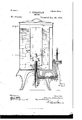
- Figure 1 is a middle vertical section of the apparatus.
- Fig. 2 is a section on .20 0c of Fig. 1.
- Fig. 3 is a plan view of the bottom blade-disk of the air-induction tube.
- Fig. 4 is a side elevation of the same with the bottom of the tube attached thereto, the parts being broken away; and
- Fig. 5 is a perspective detail of a portion of the periphcry of the tube, showing the manner of the formation of the air-openings.
- the object of my invention is to construct a churn which shall produce butter through the churning agency of air, to provide means whereby the air-currents can be forced into the milk with a maximum agitating velocity, thus producing butter in a minimum amount of time, and to provide a simple, durable, economic, and highly-superior churn.
- the main feature of the present device lies in the specific construction of the air-induction tube and in minor details of construction to be now described.
- 1 represents a general supporting frame for the several parts.
- a hand gear-wheel 2 provided with a handle 3 and meshing with a terminal pinion 4, carried at the outer projecting end of a shaft 5, mounted in depending bearings 6 and 7, forming part of the frame, and having a collar 8, secured by a binding-bolt 9, adjacent to the inner wall of the bearing 6, the object of the collar being to prevent the shaft 5 from shifting in its bearings.
- the inner end of the shaft 5 carries a bevel gear-wheel 10, which meshes with a bevel-pinion 11, secured at the lower end of a rotating spindle 12, guided in and passing through the central depending tubular bearing 13, forming a part of the frame 1.
- the upper reduced exteriorly-screw-threaded neck 14 of the tubular bearing 13 extends a suitable distance above the bottom of the receptacle 15 of the churn, a washer 16 and a suitable packing-ring 17 being passed over said neck to make a watertight joint at that point.
- a transverse pin 18 to the spindle 12 and embracing said spindle and bearing against the top surface of the neck 14 is a cylindrical block 19, the adjacent surfaces of the block and neck being made to bear tightly against one another by the resilient action of a spring 20, interposed between the pinion 11 and the lower surface of the tubular bearing 13 and encircling said spindle.
- the resiliency of the spring tends to push down 011 the pinion 11, which, being keyed to the spindle, draws the latter after it and insuring a tight joint between the block 19 and neck 14.
- Embracing the upper end of the spindle that is, the end projecting above the block 19, is the hub 21 of a hollow propelling-blade disk 22, whose periphery is connected to the hub portion by a series of inclined blades 23, the said blade-disk forming the perforated bottom of the rotatable air-induction tube or cylinder 23, located centrally within the receptacle 15 and extending up to within a suitable distance from the cover 24 thereof.
- the hub 21 loosely'embraces the spindle 12, but the lower peripheral extension of said hub is provided with a downwardly-inclined finger 25, having formed as a part thereof a concave depression 26, which the projecting end of the pin 18 is adapted to engage, and in the rotation of the spindle the engaging end of the said pin 18 will revolve the hub 21 with it, and thus impart rotation to the tube 23.
- the vertically-elongated (or practically elliptical) slots or openings 26 are cut along the periphery of the cylinder or tube 23, and at a slight distance from the base thereof, are cut the vertically-elongated (or practically elliptical) slots or openings 26, the same being formed by puncturing the plate of the periphery in a manner to have the width of the opening (or minor axis thereof) in a line with the radius of the cross-see tional circle of the tube (see Fig. 2) and the length of the opening (or major axis) substantially parallel with the general axis of the tube. (See Fig.
- these openings are characterized in having their sides circumscribed exteriorly by the outwardly-convex terminal edge 27 of the outwardly-bulging wall 28, bounding one side of the opening, and circumscribed interiorly by the inwardly-convex edge 29 of the abutting bulging wall 30, bounding the opposite side of the opening, the wall 28 being, however, the larger of the two, that is, covering more superficial area.
- the wall 28 being, however, the larger of the two, that is, covering more superficial area.
- the air will be drawn in, as indicated by arrows in Fig. 1, thence pass into and through the openings QUand into the cream confined within the receptacle, thoroughly agitating said cream and prod ucing butter in a minimum amount of time.
- a hollow rib 31, formed along the inner wall of the receptacle, serves to deflect the general rotary motion imparted to the liquid, and thus serves as an additional means of agitating the cream.
- the openings 20' tend in adirection opposite to the direction of rotation of the tube, thereby drawing the air from the out side into the interior of the tube and through the openings into the cream to be converted or operated on.
- An annular concave hood 50 opening downward and carried by the outer wall of the tube 23, serves as a further deflector of the currents of cream, thus minimizing the time in which the butter can be produced.
- a suitable rotatable air-induction tube having one or more elongated openings formed along the periphery of the tube, the major axis of each opening being substantially parallel to the axis of rotation of the tube, the minor axis of each opening being substantially in line with the radius of a cross-sectional circle of the tube, a large outwardly-convex wall bounding the outer limit of each opening, and an inwardly convex and smaller wall bounding the inward limit of each opening, substantially as set forth.
- a suitable cream-receptacle a spindle mounted in the same, a transverse pin carried by the upper end of the spindle, a rotatable air-induction tube located in the receptacle, a tubular hub forming part of said tube and adapted to pass over said spindle, and a finger formed with the hub and having an engaging depression with which the end of the transverse pin is adapted to engage during the rotation of the spindle, substantially as set forth.
- an air-induction tube or cylinder having a series of peripheral openings formed at one end thereof, a bladedisk having a series of blades radiating from a common center forming the bottom of the tube, and means for imparting rotation to the tube and disk, substantially as set forth.
- a suitable cream-receptacle In a butter-churn, a suitable cream-receptacle, a spindle projecting through the bottom of the same on either side thereof, a pinion carried at the lower end of said spindle, a coiled spring encircling the spindle and interposed between the terminal pinion and the bottom of the receptacle, and a block carried by the spindle above the bottom and adjacent thereto and bearing down upon the same by reason of the resilient action of the spring, whereby a tight joint is made be tween the spindle and the bottom, substantially as set forth.
- a suitable rotatable spindle having a bottom provided withahub adapted to embrace or pass over the upper end of the spindle, a circular block carried by the spindle and adapted to be embraced by the lower portion of the hub, a pin passed transversely through the block and spindle, and a finger forming a continuation of the tubular portion of the hub and adapted to engage the projecting end of the pin, substantially as set forth.
- an air-induction tube or cylinder having a series of openings disposed along the peripheral walls of the same, a blade-disk forming the perforated bottom of said tube, said disk having a series of inclined blades radiating from a common center to the walls of the tube, and means for imparting rotation to the tube and disk, substantially as set forth.
Landscapes
- Chemical & Material Sciences (AREA)
- Chemical Kinetics & Catalysis (AREA)
- Dairy Products (AREA)
Description
(No Model.) 2 Sheets-Sheet 1.
o. SEBASTIAN.
, h 01mm,
No. 574,282. PaLentedDeu. 29, 189 6.
wibmeooeo v Qwuawboz 4. I 0% 07720 2.62:0?2' aw;
2 Sheets-'Shet 2;
0. SEBASTIAN.
'GHURN.
Patented vDec. 29, 1896.
w 7. & M m x a 1'": nonms wsrcas cu. woro-umc. wAsuwm'on. o c.
' UNITED STATES ATENT OFFICE.
CHARLES SEBASTIAN, OF ST. LOUIS, MISSOURI, ASSIGNOR TO THOMAS J. CHENEY AND JAMES M. DAVIS, OF SAME PLACE.
CHURN.
SPECIFICATION forming part of Letters Patent No. 574,282, dated December 29, 1896.
Application filed February 24, 1896. Serial No. 580,571. (No model) To aZZ whom it may concern.-
Be it known that I, CHARLES SEBASTIAN, a citizen of the United States, residing at St. Louis, in the State of Missouri, have invented certain new and useful Improvements in Butter-Churns, of which the following is a full, clear, and exact description, reference being had to the accompanying drawings, forming a part hereof.
My invention has relation to improvements in butter-churns; and it consists in the novel arrangement and combination of parts more fully setforth in the specification, and pointed out in the claims.
In the drawings, Figure 1 is a middle vertical section of the apparatus. Fig. 2 is a section on .20 0c of Fig. 1. Fig. 3 is a plan view of the bottom blade-disk of the air-induction tube. Fig. 4 is a side elevation of the same with the bottom of the tube attached thereto, the parts being broken away; and Fig. 5 is a perspective detail of a portion of the periphcry of the tube, showing the manner of the formation of the air-openings.
The object of my invention is to construct a churn which shall produce butter through the churning agency of air, to provide means whereby the air-currents can be forced into the milk with a maximum agitating velocity, thus producing butter in a minimum amount of time, and to provide a simple, durable, economic, and highly-superior churn.
The main feature of the present device lies in the specific construction of the air-induction tube and in minor details of construction to be now described.
Referring to the drawings, 1 represents a general supporting frame for the several parts. At a convenient point of the frame is mounted a hand gear-wheel 2, provided with a handle 3 and meshing with a terminal pinion 4, carried at the outer projecting end of a shaft 5, mounted in depending bearings 6 and 7, forming part of the frame, and having a collar 8, secured by a binding-bolt 9, adjacent to the inner wall of the bearing 6, the object of the collar being to prevent the shaft 5 from shifting in its bearings. The inner end of the shaft 5 carries a bevel gear-wheel 10, which meshes with a bevel-pinion 11, secured at the lower end of a rotating spindle 12, guided in and passing through the central depending tubular bearing 13, forming a part of the frame 1. The upper reduced exteriorly-screw-threaded neck 14 of the tubular bearing 13 extends a suitable distance above the bottom of the receptacle 15 of the churn, a washer 16 and a suitable packing-ring 17 being passed over said neck to make a watertight joint at that point. Secured by a transverse pin 18 to the spindle 12 and embracing said spindle and bearing against the top surface of the neck 14 is a cylindrical block 19, the adjacent surfaces of the block and neck being made to bear tightly against one another by the resilient action of a spring 20, interposed between the pinion 11 and the lower surface of the tubular bearing 13 and encircling said spindle. The resiliency of the spring tends to push down 011 the pinion 11, which, being keyed to the spindle, draws the latter after it and insuring a tight joint between the block 19 and neck 14.
Embracing the upper end of the spindle, that is, the end projecting above the block 19, is the hub 21 of a hollow propelling-blade disk 22, whose periphery is connected to the hub portion by a series of inclined blades 23, the said blade-disk forming the perforated bottom of the rotatable air-induction tube or cylinder 23, located centrally within the receptacle 15 and extending up to within a suitable distance from the cover 24 thereof. The hub 21 loosely'embraces the spindle 12, but the lower peripheral extension of said hub is provided with a downwardly-inclined finger 25, having formed as a part thereof a concave depression 26, which the projecting end of the pin 18 is adapted to engage, and in the rotation of the spindle the engaging end of the said pin 18 will revolve the hub 21 with it, and thus impart rotation to the tube 23.
The manner of effecting the rotation of the parts is too obvious from the gear connections, as shown, and needs no detailed description.
Along the periphery of the cylinder or tube 23, and at a slight distance from the base thereof, are cut the vertically-elongated (or practically elliptical) slots or openings 26, the same being formed by puncturing the plate of the periphery in a manner to have the width of the opening (or minor axis thereof) in a line with the radius of the cross-see tional circle of the tube (see Fig. 2) and the length of the opening (or major axis) substantially parallel with the general axis of the tube. (See Fig. 5.) In addition these openings are characterized in having their sides circumscribed exteriorly by the outwardly-convex terminal edge 27 of the outwardly-bulging wall 28, bounding one side of the opening, and circumscribed interiorly by the inwardly-convex edge 29 of the abutting bulging wall 30, bounding the opposite side of the opening, the wall 28 being, however, the larger of the two, that is, covering more superficial area. Of course the nearer parallel the major axes of the several openings are with the axis of rotation of the'air-induction tube the greater will be the elficiency of the latter in drawing air into the receptacle holding the cream. The tube 23 being rotated in the direction indicated by the arrows in Figs. 2 and 3, the air will be drawn in, as indicated by arrows in Fig. 1, thence pass into and through the openings QUand into the cream confined within the receptacle, thoroughly agitating said cream and prod ucing butter in a minimum amount of time. A hollow rib 31, formed along the inner wall of the receptacle, serves to deflect the general rotary motion imparted to the liquid, and thus serves as an additional means of agitating the cream. As seen by the arrow in Fig. 2, the openings 20' tend in adirection opposite to the direction of rotation of the tube, thereby drawing the air from the out side into the interior of the tube and through the openings into the cream to be converted or operated on. An annular concave hood 50, opening downward and carried by the outer wall of the tube 23, serves as a further deflector of the currents of cream, thus minimizing the time in which the butter can be produced.
Having described my invention, what I claim is- 1. In a butter-churn, a suitable rotatable air-induction tube, having one or more elongated openings formed along the periphery of the tube, the major axis of each opening being substantially parallel to the axis of rotation of the tube, the minor axis of each opening being substantially in line with the radius of a cross-sectional circle of the tube, a large outwardly-convex wall bounding the outer limit of each opening, and an inwardly convex and smaller wall bounding the inward limit of each opening, substantially as set forth.
2. In a butter-churn, a suitable cream-receptacle, a spindle mounted in the same, a transverse pin carried by the upper end of the spindle, a rotatable air-induction tube located in the receptacle, a tubular hub forming part of said tube and adapted to pass over said spindle, and a finger formed with the hub and having an engaging depression with which the end of the transverse pin is adapted to engage during the rotation of the spindle, substantially as set forth.
3. In a butter-churn, an air-induction tube or cylinder, having a series of peripheral openings formed at one end thereof, a bladedisk having a series of blades radiating from a common center forming the bottom of the tube, and means for imparting rotation to the tube and disk, substantially as set forth.
l. In a butter-churn, a suitable cream-receptacle, a spindle projecting through the bottom of the same on either side thereof, a pinion carried at the lower end of said spindle, a coiled spring encircling the spindle and interposed between the terminal pinion and the bottom of the receptacle, and a block carried by the spindle above the bottom and adjacent thereto and bearing down upon the same by reason of the resilient action of the spring, whereby a tight joint is made be tween the spindle and the bottom, substantially as set forth.
5. In a butter-churn, a suitable rotatable spindle, an air-induction tube having a bottom provided withahub adapted to embrace or pass over the upper end of the spindle, a circular block carried by the spindle and adapted to be embraced by the lower portion of the hub, a pin passed transversely through the block and spindle, and a finger forming a continuation of the tubular portion of the hub and adapted to engage the projecting end of the pin, substantially as set forth.
0. In a butter-churn, an air-induction tube or cylinder, having a series of openings disposed along the peripheral walls of the same, a blade-disk forming the perforated bottom of said tube, said disk having a series of inclined blades radiating from a common center to the walls of the tube, and means for imparting rotation to the tube and disk, substantially as set forth.
In testimony whereof I affix my signature in presence of two witnesses.
CHARLES SEBASTIAN.
\Vitnesses:
ALFRED A. MATHEY, EMIL STAREK.
IlO
Publications (1)
| Publication Number | Publication Date |
|---|---|
| US574282A true US574282A (en) | 1896-12-29 |
Family
ID=2642977
Family Applications (1)
| Application Number | Title | Priority Date | Filing Date |
|---|---|---|---|
| US574282D Expired - Lifetime US574282A (en) | sebastian |
Country Status (1)
| Country | Link |
|---|---|
| US (1) | US574282A (en) |
Cited By (4)
| Publication number | Priority date | Publication date | Assignee | Title |
|---|---|---|---|---|
| US2427776A (en) * | 1945-02-08 | 1947-09-23 | Goldman Bronislaw | Evaporator |
| US3087198A (en) * | 1960-07-08 | 1963-04-30 | Phillips Petroleum Co | Rollers for film quench bath |
| US3251578A (en) * | 1961-06-15 | 1966-05-17 | Socony Mobil Oil Co Inc | Dispersing and grinding apparatus and method of dispersing and grinding paste |
| US6568844B1 (en) * | 1998-01-19 | 2003-05-27 | Novaseptic Equipment Ab | Device for in-vessel treatment |
-
0
- US US574282D patent/US574282A/en not_active Expired - Lifetime
Cited By (4)
| Publication number | Priority date | Publication date | Assignee | Title |
|---|---|---|---|---|
| US2427776A (en) * | 1945-02-08 | 1947-09-23 | Goldman Bronislaw | Evaporator |
| US3087198A (en) * | 1960-07-08 | 1963-04-30 | Phillips Petroleum Co | Rollers for film quench bath |
| US3251578A (en) * | 1961-06-15 | 1966-05-17 | Socony Mobil Oil Co Inc | Dispersing and grinding apparatus and method of dispersing and grinding paste |
| US6568844B1 (en) * | 1998-01-19 | 2003-05-27 | Novaseptic Equipment Ab | Device for in-vessel treatment |
Similar Documents
| Publication | Publication Date | Title |
|---|---|---|
| US871906A (en) | Machine for churning or washing. | |
| US56520A (en) | Improvement in churns | |
| US1039572A (en) | Churn. | |
| US661207A (en) | Cream-separator. | |
| US903042A (en) | Churn. | |
| US191562A (en) | Improvement in rotary churns | |
| US786525A (en) | Churn-dasher. | |
| US865030A (en) | Churn. | |
| US850525A (en) | Churn. | |
| US271130A (en) | James dawsok | |
| US161633A (en) | Improvement | |
| US955672A (en) | Egg-beater. | |
| US1070147A (en) | Churn. | |
| US655009A (en) | Churn. | |
| US526607A (en) | William p | |
| US237598A (en) | Churn | |
| US461247A (en) | Churn | |
| US1019055A (en) | Cake-mixer. | |
| US1049056A (en) | Churn-operating mechanism. | |
| US412934A (en) | Churn | |
| US157456A (en) | Improvement in egg-beaters | |
| US794490A (en) | Churn. | |
| US660513A (en) | Egg-beater and churn. | |
| US639022A (en) | Churn. | |
| US1056778A (en) | Churn. |