US5733111A - Gerotor pump having inlet and outlet relief ports - Google Patents

Gerotor pump having inlet and outlet relief ports Download PDF

Info

Publication number
US5733111A
US5733111A US08/753,815 US75381596A US5733111A US 5733111 A US5733111 A US 5733111A US 75381596 A US75381596 A US 75381596A US 5733111 A US5733111 A US 5733111A
Authority
US
United States
Prior art keywords
inlet
pumping chamber
pump
outlet
relief
Prior art date
Legal status (The legal status is an assumption and is not a legal conclusion. Google has not performed a legal analysis and makes no representation as to the accuracy of the status listed.)
Expired - Fee Related
Application number
US08/753,815
Inventor
Dequan Yu
Gerard Cronin
Ronald Engel
Current Assignee (The listed assignees may be inaccurate. Google has not performed a legal analysis and makes no representation or warranty as to the accuracy of the list.)
Ford Global Technologies LLC
Original Assignee
Ford Global Technologies LLC
Priority date (The priority date is an assumption and is not a legal conclusion. Google has not performed a legal analysis and makes no representation as to the accuracy of the date listed.)
Filing date
Publication date
Application filed by Ford Global Technologies LLC filed Critical Ford Global Technologies LLC
Priority to US08/753,815 priority Critical patent/US5733111A/en
Assigned to FORD MOTOR COMPANY reassignment FORD MOTOR COMPANY ASSIGNMENT OF ASSIGNORS INTEREST (SEE DOCUMENT FOR DETAILS). Assignors: YU, DEQUAN, CRONIN, GERARD, ENGEL, RONALD
Priority to DE19746505A priority patent/DE19746505C2/en
Assigned to FORD GLOBAL TECHNOLOGIES, INC. reassignment FORD GLOBAL TECHNOLOGIES, INC. ASSIGNMENT OF ASSIGNORS INTEREST (SEE DOCUMENT FOR DETAILS). Assignors: FORD MOTOR COMPANY
Priority to GB9725238A priority patent/GB2324573B/en
Application granted granted Critical
Publication of US5733111A publication Critical patent/US5733111A/en
Anticipated expiration legal-status Critical
Expired - Fee Related legal-status Critical Current

Links

Images

Classifications

    • FMECHANICAL ENGINEERING; LIGHTING; HEATING; WEAPONS; BLASTING
    • F04POSITIVE - DISPLACEMENT MACHINES FOR LIQUIDS; PUMPS FOR LIQUIDS OR ELASTIC FLUIDS
    • F04CROTARY-PISTON, OR OSCILLATING-PISTON, POSITIVE-DISPLACEMENT MACHINES FOR LIQUIDS; ROTARY-PISTON, OR OSCILLATING-PISTON, POSITIVE-DISPLACEMENT PUMPS
    • F04C2/00Rotary-piston machines or pumps
    • F04C2/08Rotary-piston machines or pumps of intermeshing-engagement type, i.e. with engagement of co-operating members similar to that of toothed gearing
    • F04C2/082Details specially related to intermeshing engagement type machines or pumps
    • F04C2/088Elements in the toothed wheels or the carter for relieving the pressure of fluid imprisoned in the zones of engagement
    • FMECHANICAL ENGINEERING; LIGHTING; HEATING; WEAPONS; BLASTING
    • F04POSITIVE - DISPLACEMENT MACHINES FOR LIQUIDS; PUMPS FOR LIQUIDS OR ELASTIC FLUIDS
    • F04CROTARY-PISTON, OR OSCILLATING-PISTON, POSITIVE-DISPLACEMENT MACHINES FOR LIQUIDS; ROTARY-PISTON, OR OSCILLATING-PISTON, POSITIVE-DISPLACEMENT PUMPS
    • F04C15/00Component parts, details or accessories of machines, pumps or pumping installations, not provided for in groups F04C2/00 - F04C14/00
    • F04C15/0042Systems for the equilibration of forces acting on the machines or pump
    • F04C15/0049Equalization of pressure pulses

Definitions

  • This invention relates to gerotor pumps, and more particularly, to pressure relief ports in gerotor pumps.
  • Gerotor type hydraulic pumps typically include internally toothed and externally toothed gear members rotatably disposed within a pump housing.
  • the teeth on the respective gears cooperate to define a plurality of variable volume pumping cheers whereupon during rotation of the gear members, a pumping chamber increases in volume to a maximum volume, then decreases in volume. Fluid from the pump's low pressure inlet port is drawn into pumping chambers that are increasing in volume. Upon further rotation of the gerotor when the pumping chambers are decreasing in volume, the fluid is pushed out through the pump's outlet port at a higher pressure.
  • Deadlock or hydrostatic lock may cause the torque necessary to drive the gerotor pump to increase dramatically, thereby resulting in pumping losses, reduced pumping efficiency and increased pump noise.
  • U.S. Pat. No. 3,034,448 discloses a gerotor pump having such relief ports.
  • a trapping relief groove 71 extends 180° in the pump housing to communicate between a low pressure pumping chamber and a high pressure pumping chamber.
  • the relief groove 71 does not, however, communicate with the inlet or outlet ports.
  • the gerotor in '448 uses balance ports 70 which are larger than groove 71. That is, because the relative positions of the maximum volume (high pressure) pumping chamber and the minimum volume (low pressure) pumping chamber may be different than the nominal 180° in different gerotor pumps, the balance ports are used to compensate for this variability.
  • the design of the gerotor in '448 is undesirable because it provides a continual, uncontrolled and excessive leakage path between the high and low pressure pumping chambers.
  • leakage occurs from the pumping chamber even at positions where deadlock or hydrostatic lock does not occur.
  • the fluid which is relieved from the pumping chamber of the gerotor in '448 is never pumped out to the outlet because the relief groove and balance ports do not communicate with the outlet port. Excessive leakage which is not directed to the outlet is undesirable because the pumping efficiency is decreased.
  • An object of the present invention is to provide a gerotor pump having relief ports which intermittently communicate with the open mesh pumping chamber so as to relieve over-pressure in the open mesh pumping chamber and reduce excessive leakage from the open mesh pumping chamber.
  • This object is achieved and disadvantages of prior art approached are overcome by providing a novel gerotor pump.
  • the gerotor pump includes a pump housing, an internally toothed gear member rotatably disposed within the pump housing, and an externally tooth gear member rotatably disposed within the pump housing.
  • the externally toothed gear cooperates with the internally toothed gear member to define a plurality of variable volume pumping chambers whereupon during rotation of the gear members, a pumping chamber increases in volume to a maximum volume, then decreases in volume.
  • a generally arcuate inlet channel is formed in the pump housing and communicates exclusively with pumping chambers that are increasing in volume.
  • a generally arcuate outlet channel is formed in the pump housing and communicates exclusively with pumping chambers that are decreasing in volume.
  • the inlet and outlet channels are separated such that the channels are prevented from simultaneously communicating with an open mesh pumping chamber.
  • a pair of relief ports are superimposed on and directly communicate respectively with the inlet and outlet channels. The relief ports simultaneously communicate with the open mesh pumping chamber so as to provide an intermittent controlled leak from the open mesh pumping chamber.
  • fluid in the open mesh pumping chamber vents into the relief port superimposed on and communicating with the outlet channel while continuing to communicate with the relief port superimposed on and communicating with the inlet channel.
  • fluid in the open mesh pumping chamber is prevented from venting into the relief port superimposed on and communicating with the inlet channel while continuing to communicate with the relief port superimposed on and communicating with the outlet channel. Fluid pressure in and excessive fluid leakage from the open mesh pumping chamber is therefore limited.
  • An advantage of the present invention is that fluid over-pressure in the open mesh pumping chamber of the gerotor pump is reduced.
  • Another advantage of the present invention is that fluid leakage from the open mesh pumping chamber is controlled.
  • Still another advantage of the present invention is that an easy to manufacture gerotor pump having limited pump-to-pump variability is provided.
  • Yet another advantage of the present invention is that a gerotor pump having a relatively high pumping efficiency is provided.
  • FIG. 1 is a diagrammatic representation of a gerotor pump according to the present invention
  • FIG. 2 is a plan view of the cover to the gerotor pump according to the present invention.
  • FIG. 3 is cross-section view of the gerotor pump taken along line 3--3 of FIG. 1;
  • FIGS. 4 and 5 are alternative embodiments of the present invention.
  • gerotor pump 10 includes pump housing 12, having pump body 14 and pump cover 16, and internally and externally toothed gear members 18, 20, each having a plurality of teeth 26, disposed within housing 12.
  • Externally toothed gear member 20 is supported for rotation on axis 22 of shaft 24 and keyed thereto by key 27 fitting into respective keyways on gear 20 and shaft 22.
  • internally toothed gear member 18 is supported for rotation about an axis which is spaced from axis 22 so as to provide the necessary gear eccentricity for proper operation of gerotor pump 10.
  • externally toothed gear member 20 has one less tooth 26 than that of internally tooth gear member 18. Teeth 26 on the respective gears cooperate to define a plurality of variable volume pumping chambers 28 whereupon during rotation of gear members 18, 20, a pumping chamber 28 increases in volume to a maximum volume, then decreases in volume.
  • Pump housing 12 also includes arcuately shaped inlet and outlet channels 30, 32 formed in pump body 14.
  • Inlet channel 30 communicates exclusively with pumping chambers 28 that are increasing in volume and outlet channel 32 communicates exclusively with pumping chambers 28 that are decreasing in volume. Accordingly, as gear members 18, 20 rotate in the direction shown as "R", fluid is drawn in through inlet channel 30 by the action of the increasing volume pumping chambers 28 and is pumped out through outlet channel 32 at a higher pressure by the action of the decreasing pumping chambers 28.
  • inlet and outlet channels 30, 32 are prevented from simultaneously communicating with an open mesh pumping chamber 34, which is near a maximum volume. That is, as the fluid transitions from the low pressure inlet channel 30 to the high pressure outlet channel 32, the fluid in the open mesh pumping chamber 34 is prevented from directly communicating with either the inlet or outlet channels 30, 32.
  • inlet and outlet channels 30, 32 are separated by an angle, shown as ⁇ 1 , which is between about 100% and about 120% of a nominal separation angle ⁇ (see FIG. 3).
  • This nominal separation angle ⁇ is defined by 360° divided by the number of teeth 26 on externally toothed gear member 20 and represents the angle when the open mesh pumping chamber 34 is at maximum volume.
  • the separation angle ⁇ 1 separating inlet and outlet channels 30, 32 would be between about 36° and about 43.2°, which represents between about 100% and about 120% of the nominal separation angle ⁇ .
  • cover 16 of pump housing 12 is shown such that the surface shown faces gear members 18, 20. That is, to assemble cover 16, shown in FIG. 2, to pump body 14, shown in FIG. 1, cover 16 must be turned over and placed on top of pump body 14.
  • cover 16 is formed with a pair of arcuately shaped relief ports 40, 42 and are positioned in cover 16 so as to be superimposed on and directly communicate with inlet and outlet channels 30, 32, respectively when cover 16 is assembled to pump body 14.
  • relief ports 40, 42 arcuately extend from inlet and outlet channels 30, 32 and are separated by an angle ⁇ 2 , which is between about 80% and about 95% of the nominal separation angle ⁇ as earlier defined. Accordingly, ⁇ 2 ranges between about 28.8° and about 34.2° when the number of teeth on externally toothed gear member 20 is ten.
  • FIG. 3 is a diagrammatic cross-section of gerotor 10, because the separation angle ⁇ 2 separating relief ports 40, 42 is smaller than the separation angle ⁇ 1 separating inlet and outlet channels 30, 32, relief ports 40, 42 communicate with the open mesh pumping chamber 34 so as to provide an intermittent controlled leak from the open mesh pumping chamber 34.
  • relief ports 40, 42 communicate with the open mesh pumping chamber 34 so as to provide an intermittent controlled leak from the open mesh pumping chamber 34.
  • edges 44, 46 of relief ports 40, 42 respectively have an infinite slope relative to plane 48 of cover 16. Those skilled in the art will recognize in view of this disclosure that edges 44, 46 may have a gradual slope. Indeed, edges 44, 46 may be a fillet or the like.
  • relief ports 40, 42 extend a depth "h", shown in FIG. 3, into pump cover 16 of about 5% to about 15% of the combined depth "h"+”h 1 ", where "h 1 " represents the depth of the inlet and outlet channels 30, 32.
  • the depth "h” of relief ports 40, 42 is controlled so as to act as a flow orifice limiting over-pressure and excessive leakage as previously described.
  • the depth "h” is preferably about 1 millimeter. This allows for an easily manufacturable pump cover 16 in that pump cover 16 may be stamped from plate steel, with relief ports 40, 42 stamped directly therein.
  • relief ports 40, 42 are superimposed on inlet and outlet channels 30, 32, respectively, relief ports 30, 32 may be considered as comprising a portion of inlet and outlet channels 30, 32. As such, inlet and outlet channels 30, 32 may be considered to be stepped such that the each channel has a main flow portion for handling the inlet and outlet flows as well as a pressure relief portion for relieving pressure in the open mesh pumping chamber 34 yet controlling leakage therefrom.
  • two relief ports 40, 42 are formed within housing 12 so as to be superimposed on inlet and outlet ports 30, 32, respectively.
  • two relief ports 40, 42 By utilizing two relief ports 40, 42, a less controlled manufacturing tolerance is necessary. That is, suppose gerotor pump 10 is provided with only relief port 42, the point at which open mesh pumping chamber 34 begins to communicate with relief port 42 must be precisely controlled. With two relief ports 40, 42, the point at which open mesh pumping chamber 34 begins to communicate with relief port 42 need not be precisely controlled because venting will occur into relief port 40 should the volume in the open mesh pumping chamber begin to decrease prior to communicating with relief port 42. In addition, pressure fluctuations in the open mesh pumping chamber 34 may be limited with two, relatively shallow relief ports 40, 42 rather than one, relatively deeper relief port 42. Moreover, two relief ports 40, 42 have the added benefit of reducing inlet port flow velocity, which may otherwise tend to produce cavitation of the fluid flowing therethrough.
  • relief ports 40 and 42 are formed in pump body 14, rather than in cover 16, and arcuately extend from inlet and outlet channels 30, 32, respectively.
  • inlet and outlet channels 30, 32 are separated by an angle ⁇ 1 , which is between about 100% and about 120% of the nominal separation angle ⁇
  • relief ports 40, 42 are separated by an angle ⁇ 2 , which is between about 80% and about 95% of the nominal separation angle ⁇ . Because ⁇ 2 is less than ⁇ 1 , relief ports 40, 42 communicate with the open mesh pumping chamber 34 so as to provide an intermittent controlled leak from the open mesh pumping chamber 34. As described with reference to FIGS.
  • relief ports 40, 42 extend a depth "h” into pump body 14 between about 5% to about 15% of the combined depth “h”+”h 1 ", where "h 1 " represents the depth of the inlet and outlet channels 30, 32.
  • FIG. 5 A further embodiment of the present invention is shown in FIG. 5.
  • relief ports 40, 42 are formed in both the pump body 14 and pump cover 16 and have the same dimensional relationships ( ⁇ , ⁇ 1 , ⁇ 2 , "h” and “h 1 ") as that described with reference to FIGS. 1-4.
  • inlet and outlet channels 30, 32 are also formed in pump body 14 and pump cover 16. This embodiment is preferred when handling higher flow rates and pressures.

Landscapes

  • Engineering & Computer Science (AREA)
  • Mechanical Engineering (AREA)
  • General Engineering & Computer Science (AREA)
  • Rotary Pumps (AREA)
  • Details And Applications Of Rotary Liquid Pumps (AREA)

Abstract

A gerotor pump includes a pair of relief ports superimposed on and directly communicating with the pump's inlet and outlet channels, respectively. The relief ports simultaneously communicate with an open mesh pumping chamber so as to provide an intermittent controlled leak from the open mesh pumping chamber. Upon rotation of the gear members of the gerotor pump when the volume in the open mesh pumping chamber is increasing to a maximum volume, fluid in the open mesh pumping chamber vents into the relief port superimposed on and communicating with the outlet channel while continuing to communicate with the relief port superimposed on and communicating with the inlet channel. Upon further rotation of the gear member when the volume in the open mesh pumping is decreasing, fluid in the open mesh pumping chamber is prevented from venting into the relief port superimposed and communicating with the inlet channel while continuing to communicate with the relief port superimposed on and communicating with the outlet channel. Thus, fluid over-pressure in an excessive fluid leakage from the open mesh pumping chamber is limited.

Description

FIELD OF THE INVENTION
This invention relates to gerotor pumps, and more particularly, to pressure relief ports in gerotor pumps.
BACKGROUND OF THE INVENTION
Gerotor type hydraulic pumps typically include internally toothed and externally toothed gear members rotatably disposed within a pump housing. The teeth on the respective gears cooperate to define a plurality of variable volume pumping cheers whereupon during rotation of the gear members, a pumping chamber increases in volume to a maximum volume, then decreases in volume. Fluid from the pump's low pressure inlet port is drawn into pumping chambers that are increasing in volume. Upon further rotation of the gerotor when the pumping chambers are decreasing in volume, the fluid is pushed out through the pump's outlet port at a higher pressure. Because of the incompressibility of the fluid being pumped, when a certain pumping chamber is between the inlet and outlet ports (open mesh) and begins to decrease in volume, a situation known as "deadlock" or "hydrostatic lock" occurs. Deadlock or hydrostatic lock may cause the torque necessary to drive the gerotor pump to increase dramatically, thereby resulting in pumping losses, reduced pumping efficiency and increased pump noise.
Prior art devices have overcome the problem of deadlock or hydrostatic lock by incorporating relief ports which communicate with the pumping chamber to relieve the pressure therein. U.S. Pat. No. 3,034,448 ('448) discloses a gerotor pump having such relief ports. A trapping relief groove 71 extends 180° in the pump housing to communicate between a low pressure pumping chamber and a high pressure pumping chamber. The relief groove 71 does not, however, communicate with the inlet or outlet ports. To compensate for pump-to-pump variability in the actual position of the maximum and minimum volume pumping chamber relative to the groove 71, the gerotor in '448 uses balance ports 70 which are larger than groove 71. That is, because the relative positions of the maximum volume (high pressure) pumping chamber and the minimum volume (low pressure) pumping chamber may be different than the nominal 180° in different gerotor pumps, the balance ports are used to compensate for this variability.
The inventors of the present invention have found certain disadvantages with this prior art device. For example, the design of the gerotor in '448 is undesirable because it provides a continual, uncontrolled and excessive leakage path between the high and low pressure pumping chambers. Thus, leakage occurs from the pumping chamber even at positions where deadlock or hydrostatic lock does not occur. The fluid which is relieved from the pumping chamber of the gerotor in '448 is never pumped out to the outlet because the relief groove and balance ports do not communicate with the outlet port. Excessive leakage which is not directed to the outlet is undesirable because the pumping efficiency is decreased. That is, pumping energy is wasted in '448 because the fluid relieved from the pumping chamber is not utilized, but merely shuttled between high and low pressure pumping chambers. In addition, the width of groove 71 together with the location of the balance ports 70 must be tightly controlled to limit pump-to-pump variation of the volume of fluid leaking through groove 71. As a result, the relief port of '448 is a relatively complex design to manufacture and mass production may be compromised. Therefore, a need exist to relieve the pressure in the open mesh pumping chamber yet prevent excessive or uncontrolled leaking from the open mesh pumping chamber while maintaining relatively high pumping efficiency and consistency between mass-produced pumps.
SUMMARY OF THE INVENTION
An object of the present invention is to provide a gerotor pump having relief ports which intermittently communicate with the open mesh pumping chamber so as to relieve over-pressure in the open mesh pumping chamber and reduce excessive leakage from the open mesh pumping chamber. This object is achieved and disadvantages of prior art approached are overcome by providing a novel gerotor pump. In one particular aspect of the invention, the gerotor pump includes a pump housing, an internally toothed gear member rotatably disposed within the pump housing, and an externally tooth gear member rotatably disposed within the pump housing. The externally toothed gear cooperates with the internally toothed gear member to define a plurality of variable volume pumping chambers whereupon during rotation of the gear members, a pumping chamber increases in volume to a maximum volume, then decreases in volume. A generally arcuate inlet channel is formed in the pump housing and communicates exclusively with pumping chambers that are increasing in volume. A generally arcuate outlet channel is formed in the pump housing and communicates exclusively with pumping chambers that are decreasing in volume. The inlet and outlet channels are separated such that the channels are prevented from simultaneously communicating with an open mesh pumping chamber. A pair of relief ports are superimposed on and directly communicate respectively with the inlet and outlet channels. The relief ports simultaneously communicate with the open mesh pumping chamber so as to provide an intermittent controlled leak from the open mesh pumping chamber. Upon rotation of the gear members when the volume in the open mesh pumping chamber is increasing to a maximum volume, fluid in the open mesh pumping chamber vents into the relief port superimposed on and communicating with the outlet channel while continuing to communicate with the relief port superimposed on and communicating with the inlet channel. Upon further rotation of the gear members when the volume in the open mesh pumping chamber is decreasing, fluid in the open mesh pumping chamber is prevented from venting into the relief port superimposed on and communicating with the inlet channel while continuing to communicate with the relief port superimposed on and communicating with the outlet channel. Fluid pressure in and excessive fluid leakage from the open mesh pumping chamber is therefore limited.
An advantage of the present invention is that fluid over-pressure in the open mesh pumping chamber of the gerotor pump is reduced.
Another advantage of the present invention is that fluid leakage from the open mesh pumping chamber is controlled.
Still another advantage of the present invention is that an easy to manufacture gerotor pump having limited pump-to-pump variability is provided.
Yet another advantage of the present invention is that a gerotor pump having a relatively high pumping efficiency is provided.
Other objects, features and advantages of the present invention will be readily appreciated by the reader of this specification.
BRIEF DESCRIPTION OF THE DRAWINGS
The invention will now be described, by way of example, with reference to the accompany drawings, in which:
FIG. 1 is a diagrammatic representation of a gerotor pump according to the present invention;
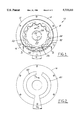
FIG. 2 is a plan view of the cover to the gerotor pump according to the present invention;
FIG. 3 is cross-section view of the gerotor pump taken along line 3--3 of FIG. 1; and,
FIGS. 4 and 5 are alternative embodiments of the present invention.
DETAILED DESCRIPTION OF THE PREFERRED EMBODIMENT
Referring to the Figures, and in particular to FIGS. 1-3, gerotor pump 10 includes pump housing 12, having pump body 14 and pump cover 16, and internally and externally toothed gear members 18, 20, each having a plurality of teeth 26, disposed within housing 12. Externally toothed gear member 20 is supported for rotation on axis 22 of shaft 24 and keyed thereto by key 27 fitting into respective keyways on gear 20 and shaft 22. internally toothed gear member 18 is supported for rotation about an axis which is spaced from axis 22 so as to provide the necessary gear eccentricity for proper operation of gerotor pump 10. In addition, externally toothed gear member 20 has one less tooth 26 than that of internally tooth gear member 18. Teeth 26 on the respective gears cooperate to define a plurality of variable volume pumping chambers 28 whereupon during rotation of gear members 18, 20, a pumping chamber 28 increases in volume to a maximum volume, then decreases in volume.
Pump housing 12 also includes arcuately shaped inlet and outlet channels 30, 32 formed in pump body 14. Inlet channel 30 communicates exclusively with pumping chambers 28 that are increasing in volume and outlet channel 32 communicates exclusively with pumping chambers 28 that are decreasing in volume. Accordingly, as gear members 18, 20 rotate in the direction shown as "R", fluid is drawn in through inlet channel 30 by the action of the increasing volume pumping chambers 28 and is pumped out through outlet channel 32 at a higher pressure by the action of the decreasing pumping chambers 28.
According to the present invention, inlet and outlet channels 30, 32 are prevented from simultaneously communicating with an open mesh pumping chamber 34, which is near a maximum volume. That is, as the fluid transitions from the low pressure inlet channel 30 to the high pressure outlet channel 32, the fluid in the open mesh pumping chamber 34 is prevented from directly communicating with either the inlet or outlet channels 30, 32. To accomplish this, in the embodiment described herein, inlet and outlet channels 30, 32 are separated by an angle, shown as θ1, which is between about 100% and about 120% of a nominal separation angle θ (see FIG. 3). This nominal separation angle θ is defined by 360° divided by the number of teeth 26 on externally toothed gear member 20 and represents the angle when the open mesh pumping chamber 34 is at maximum volume. For example, suppose externally toothed gear member 20 has ten teeth. The nominal separation angle θ would be 36°. Thus, the separation angle θ1 separating inlet and outlet channels 30, 32 would be between about 36° and about 43.2°, which represents between about 100% and about 120% of the nominal separation angle θ.
Referring now in particular to FIG. 2, cover 16 of pump housing 12 is shown such that the surface shown faces gear members 18, 20. That is, to assemble cover 16, shown in FIG. 2, to pump body 14, shown in FIG. 1, cover 16 must be turned over and placed on top of pump body 14. According to the present invention, cover 16 is formed with a pair of arcuately shaped relief ports 40, 42 and are positioned in cover 16 so as to be superimposed on and directly communicate with inlet and outlet channels 30, 32, respectively when cover 16 is assembled to pump body 14. Thus, relief ports 40, 42 arcuately extend from inlet and outlet channels 30, 32 and are separated by an angle θ2, which is between about 80% and about 95% of the nominal separation angle θ as earlier defined. Accordingly, θ2 ranges between about 28.8° and about 34.2° when the number of teeth on externally toothed gear member 20 is ten.
Turning now in particular to FIG. 3, which is a diagrammatic cross-section of gerotor 10, because the separation angle θ2 separating relief ports 40, 42 is smaller than the separation angle θ1 separating inlet and outlet channels 30, 32, relief ports 40, 42 communicate with the open mesh pumping chamber 34 so as to provide an intermittent controlled leak from the open mesh pumping chamber 34. As a result, upon rotation of gear members 18, 22, when the volume in the open mesh pumping chamber 34 is increasing to the maximum volume, fluid in the open mesh pumping chamber 34 vents into relief port 42 superimposed on and communicating with outlet channel 32 while continuing to communicate with relief port 40 superimposed on and communicating with inlet channel 30. Upon further rotation of gear members 18, 20 when the volume in the open mesh pumping chamber 34 is decreasing, fluid in the open mesh pumping chamber 34 is prevented from venting into relief port 40 superimposed on and communicating with inlet port 30 while continuing to communicate with relief port 42 superimposed on and communicating with outlet channel 32. Thus, fluid over-pressure in and excessive fluid leakage from the open mesh pumping chamber 34 is limited. As shown in FIG. 3, edges 44, 46 of relief ports 40, 42, respectively have an infinite slope relative to plane 48 of cover 16. Those skilled in the art will recognize in view of this disclosure that edges 44, 46 may have a gradual slope. Indeed, edges 44, 46 may be a fillet or the like.
To further limit the amount of over-pressure in the open mesh pumping chamber 34 yet control leakage from the open mesh pumping chamber 34, relief ports 40, 42 extend a depth "h", shown in FIG. 3, into pump cover 16 of about 5% to about 15% of the combined depth "h"+"h1 ", where "h1 " represents the depth of the inlet and outlet channels 30, 32. Thus, the depth "h" of relief ports 40, 42 is controlled so as to act as a flow orifice limiting over-pressure and excessive leakage as previously described. In a preferred embodiment, the depth "h" is preferably about 1 millimeter. This allows for an easily manufacturable pump cover 16 in that pump cover 16 may be stamped from plate steel, with relief ports 40, 42 stamped directly therein.
Because relief ports 40, 42 are superimposed on inlet and outlet channels 30, 32, respectively, relief ports 30, 32 may be considered as comprising a portion of inlet and outlet channels 30, 32. As such, inlet and outlet channels 30, 32 may be considered to be stepped such that the each channel has a main flow portion for handling the inlet and outlet flows as well as a pressure relief portion for relieving pressure in the open mesh pumping chamber 34 yet controlling leakage therefrom.
According to the present invention, two relief ports 40, 42 are formed within housing 12 so as to be superimposed on inlet and outlet ports 30, 32, respectively. By utilizing two relief ports 40, 42, a less controlled manufacturing tolerance is necessary. That is, suppose gerotor pump 10 is provided with only relief port 42, the point at which open mesh pumping chamber 34 begins to communicate with relief port 42 must be precisely controlled. With two relief ports 40, 42, the point at which open mesh pumping chamber 34 begins to communicate with relief port 42 need not be precisely controlled because venting will occur into relief port 40 should the volume in the open mesh pumping chamber begin to decrease prior to communicating with relief port 42. In addition, pressure fluctuations in the open mesh pumping chamber 34 may be limited with two, relatively shallow relief ports 40, 42 rather than one, relatively deeper relief port 42. Moreover, two relief ports 40, 42 have the added benefit of reducing inlet port flow velocity, which may otherwise tend to produce cavitation of the fluid flowing therethrough.
Turning now to FIG. 4, an alternative embodiment according to the present invention is shown. Here, relief ports 40 and 42 are formed in pump body 14, rather than in cover 16, and arcuately extend from inlet and outlet channels 30, 32, respectively. As discussed with reference to FIG. 3, inlet and outlet channels 30, 32 are separated by an angle θ1, which is between about 100% and about 120% of the nominal separation angle θ, and relief ports 40, 42 are separated by an angle θ2, which is between about 80% and about 95% of the nominal separation angle θ. Because θ2 is less than θ1, relief ports 40, 42 communicate with the open mesh pumping chamber 34 so as to provide an intermittent controlled leak from the open mesh pumping chamber 34. As described with reference to FIGS. 1-3, upon rotation of gear members 18, 22, when the volume in the open mesh pumping chamber 34 is increasing to the maximum volume, fluid in the open mesh pumping chamber 34 vents into relief port 42 superimposed on and communicating with outlet channel 32 while continuing to communicate with relief port 40 superimposed on and communicating with inlet channel 30. Upon further rotation of gear members 18, 20 when the volume in the open mesh pumping chamber 34 is decreasing, fluid in the open mesh pumping chamber 34 is prevented from venting into relief port 40 superimposed on and communicating with inlet port 30 while continuing to communicate with relief port 42 superimposed on and communicating with outlet channel 32. Thus, fluid over-pressure in and excessive fluid leakage from the open mesh pumping chamber 34 is limited. In addition, to control the leakage from the open mesh pumping chamber 34, relief ports 40, 42 extend a depth "h" into pump body 14 between about 5% to about 15% of the combined depth "h"+"h1 ", where "h1 " represents the depth of the inlet and outlet channels 30, 32.
A further embodiment of the present invention is shown in FIG. 5. Here, relief ports 40, 42 are formed in both the pump body 14 and pump cover 16 and have the same dimensional relationships (θ, θ1, θ2, "h" and "h1 ") as that described with reference to FIGS. 1-4. In addition, inlet and outlet channels 30, 32 are also formed in pump body 14 and pump cover 16. This embodiment is preferred when handling higher flow rates and pressures.
While the best mode for carrying out the invention has been described in detail, those skilled in the art in which this invention relates will recognized various alternatives and embodiments, including those mentioned above, in practicing the invention that has been defined by the following claims.

Claims (20)

We claim:
1. A gerotor pump for pumping fluids comprising:
a pump housing;
an internally toothed gear member rotatably disposed within said pump housing;
an externally toothed gear member rotatably disposed within said pump housing, with said externally toothed gear member cooperating with said internally toothed gear member to define a plurality of variable volume pumping chambers whereupon during rotation of said gear members, a pumping chamber increases in volume to a maximum volume then decreases in volume;
a generally arcuate inlet channel formed in said pump housing, with said inlet channel communicating exclusively with pumping chambers that are increasing in volume;
a generally arcuate outlet channel formed in said pump housing, with said outlet channel communicating exclusively with pumping chambers that are decreasing in volume, with said inlet and outlet channels being separated such that said channels are prevented from simultaneously communicating with an open mesh pumping chamber; and,
a pair of relief ports superimposed on and directly communicating with said inlet and outlet channels respectively, with said relief ports simultaneously communicating with said open mesh pumping chamber so as to provide an intermittent controlled leak from said open mesh pumping chamber, whereby, upon rotation of said gear members when the volume in said open mesh pumping chamber is increasing to said maximum volume, fluid in said open mesh pumping chamber vents into said relief port superimposed on and communicating with said outlet channel while continuing to communicate with said relief port superimposed on and communicating with said inlet channel and, upon further rotation of said gear members when the volume in said open mesh pumping chamber is decreasing, fluid in said open mesh pumping chamber is prevented from venting into said relief port superimposed on and communicating with said inlet channel while continuing to communicate with said relief port superimposed on and communicating with said outlet channel, thereby limiting fluid over-pressure in and excessive fluid leakage from said open mesh pumping chamber.
2. A gerotor pump according to claim 1 wherein said inlet and said outlet channels are separated by an angle which is between about 100% and about 120% of a nominal separation angle, with said nominal separation angle being 360° divided by the number of teeth on said externally toothed gear member.
3. A gerotor pump according to claim 1 wherein said relief ports are separated from each other by an angle which is between about 80% and about 95% of a nominal separation angle, with said nominal separation angle being 360° divided by the number of teeth on said externally toothed gear member.
4. A gerotor pump according to claim 1 wherein said housing comprises a pump body and a pump cover, with said inlet and said outlet channels being formed in said pump body and with said relief ports being formed in said pump cover.
5. A gerotor pump according to claim 1 wherein said housing comprises a pump body and a pump cover, with said inlet channel, said outlet channel and said relief ports being formed in said pump body.
6. A gerotor pump according to claim 1 wherein said housing comprises a pump body and a pump cover, with said inlet and said outlet channels being formed in said pump body and with said relief ports being formed in both said pump body and said pump cover.
7. A gerotor pump according to claim 1 wherein said relief ports have a depth of about 5% to about 15% of the combined depth of said relief ports and said channels.
8. A gerotor pump according to claim 1 wherein said relief ports comprise a portion of each said channel, respectively.
9. A gerotor pump comprising:
a pump housing;
an internally toothed gear member rotatably disposed within said pump housing;
an externally toothed gear member rotatably disposed within said pump housing, with said externally toothed gear member cooperating with said internally toothed gear member to define a plurality of variable volume pumping chambers whereupon during rotation of said gear members, a pumping chamber increases in volume to a maximum volume then decreases in volume;
a stepped inlet channel formed in said pump housing, with said stepped inlet channel having an inlet flow port and an inlet relief port superimposed on said inlet port, with said inlet flow port communicating exclusively with pumping chambers that are increasing in volume;
a stepped outlet channel formed in said pump housing, with said stepped outlet channel having an outlet flow port and an outlet relief port superimposed on said outlet port, with said outlet flow port communicating exclusively with pumping chambers that are decreasing in volume; and,
with said inlet and outlet flow ports being separated such that said inlet and outlet flow ports are prevented from simultaneously communicating with an open mesh pumping chamber and with said inlet and outlet relief ports simultaneously communicating with said open mesh pumping chamber so as to provide an intermittent controlled leak from said open mesh pumping chamber, whereby, upon rotation of said gear members when the volume in said open mesh pumping chamber is increasing to said maximum volume, fluid in said open mesh pumping chamber vents into said outlet relief port while continuing to communicate with said inlet relief port and, upon further rotation of said gear members when the volume in said open mesh pumping chamber is decreasing, fluid in said open mesh pumping chamber is prevented from venting into said inlet relief port while continuing to communicate with said outlet relief port, thereby limiting fluid over-pressure in and excessive fluid leakage from said open mesh pumping chamber.
10. A gerotor pump according to claim 9 wherein said inlet and outlet flow ports are separated by an angle which is between about 100% and about 120% of a nominal separation angle, with said nominal separation angle being 360° divided by the number of teeth on said externally toothed gear member.
11. A gerotor pump according to claim 9 wherein said inlet and outlet relief ports are separated by an angle which is between about 80% and about 95% of a nominal separation angle, with said nominal separation angle being 360° divided by the number of teeth on said externally toothed gear member.
12. A gerotor pump according to claim 9 wherein said housing comprises a pump body and a pump cover, with said inlet and outlet flow ports being formed in said pump body and with said inlet and outlet relief ports being formed in said pump cover.
13. A gerotor pump according to claim 9 wherein said housing comprises a pump body and a pump cover, with said inlet and outlet channels being formed in said pump body.
14. A gerotor pump according to claim 9 wherein said housing comprises a pump body and a pump cover, with said inlet and outlet flow ports being formed in said pump body and with said inlet and outlet relief ports being formed in both said pump body and said pump cover.
15. A gerotor pump according to claim 9 wherein said inlet and outlet relief ports have a depth of about 5% to about 15% of the depth of combined depth of said relief ports and said inlet and outlet flow ports.
16. A gerotor pump according to claim 9 wherein said channels are generally arcuate in shape.
17. A gerotor pump for pumping oil through an internal combustion engine, with said gerotor comprising:
a pump housing;
an internally toothed gear member rotatably disposed within said pump housing;
an externally toothed gear member rotatably disposed within said pump housing, with said externally toothed gear member cooperating with said internally toothed gear member to define a plurality of variable volume pumping chambers whereupon during rotation of said gear members, a pumping chamber increases in volume to a maximum volume then decreases in volume;
generally arcuate inlet and outlet channels formed in said pump housing, with each said channel having a main flow portion and a relief portion arcuately extending from said main flow portion, with said relief portions providing an intermittent controlled leak between said main flow portions, whereby, upon rotation of said gear members when the volume in an open mesh pumping chamber is increasing to said maximum volume, fluid in said open mesh pumping chamber vents into said outlet channel relief port while continuing to communicate with said inlet channel relief port and, upon further rotation of said gear members when the volume in said open mesh pumping chamber is decreasing, fluid in said open mesh pumping chamber is prevented from venting into said inlet channel relief port while continuing to communicate with said outlet channel relief port, thereby limiting fluid over-pressure in and excessive fluid leakage from said open mesh pumping chamber.
18. A gerotor pump according to claim 17 wherein said main flow portions are separated by an angle which is between about 100% and about 120% of a nominal separation angle, with said nominal separation angle being 360° divided by the number of teeth on said externally toothed gear member.
19. A gerotor pump according to claim 17 wherein said relief portions are separated by an angle which is between about 80% and about 95% of a nominal separation angle, with said nominal separation angle being 360° divided by the number of teeth on said externally toothed gear member.
20. A gerotor pump according to claim 17 wherein said relief portions have a depth of about 5% to about 15% of the depth of the combined depth of said relief portions and said main flow portions.
US08/753,815 1996-12-02 1996-12-02 Gerotor pump having inlet and outlet relief ports Expired - Fee Related US5733111A (en)

Priority Applications (3)

Application Number Priority Date Filing Date Title
US08/753,815 US5733111A (en) 1996-12-02 1996-12-02 Gerotor pump having inlet and outlet relief ports
DE19746505A DE19746505C2 (en) 1996-12-02 1997-10-22 Internal gear pump
GB9725238A GB2324573B (en) 1996-12-02 1997-12-01 Gerotor pump

Applications Claiming Priority (1)

Application Number Priority Date Filing Date Title
US08/753,815 US5733111A (en) 1996-12-02 1996-12-02 Gerotor pump having inlet and outlet relief ports

Publications (1)

Publication Number Publication Date
US5733111A true US5733111A (en) 1998-03-31

Family

ID=25032267

Family Applications (1)

Application Number Title Priority Date Filing Date
US08/753,815 Expired - Fee Related US5733111A (en) 1996-12-02 1996-12-02 Gerotor pump having inlet and outlet relief ports

Country Status (3)

Country Link
US (1) US5733111A (en)
DE (1) DE19746505C2 (en)
GB (1) GB2324573B (en)

Cited By (17)

* Cited by examiner, † Cited by third party
Publication number Priority date Publication date Assignee Title
US6113360A (en) * 1998-07-27 2000-09-05 Ford Motor Company Gerotor pump
US6454010B1 (en) 2000-06-01 2002-09-24 Pan Canadian Petroleum Limited Well production apparatus and method
EP1270900A1 (en) * 1998-07-31 2003-01-02 The Texas A & M University System Quasi-isothermal Brayon cycle engine
US20030106301A1 (en) * 1998-07-31 2003-06-12 Holtzapple Mark T. Quasi-isothermal brayton cycle engine
US6733249B2 (en) 2001-05-17 2004-05-11 Delphi Technologies, Inc. Multi-stage internal gear fuel pump
US6758656B2 (en) 2001-05-17 2004-07-06 Delphi Technologies, Inc. Multi-stage internal gear/turbine fuel pump
US6767181B2 (en) 2002-10-10 2004-07-27 Visteon Global Technologies, Inc. Fuel pump
US20040154328A1 (en) * 1998-07-31 2004-08-12 Holtzapple Mark T. Vapor-compression evaporative air conditioning systems and components
US20040223841A1 (en) * 2003-05-06 2004-11-11 Dequan Yu Fuel pump impeller
US20040258545A1 (en) * 2003-06-23 2004-12-23 Dequan Yu Fuel pump channel
US20060239849A1 (en) * 2002-02-05 2006-10-26 Heltzapple Mark T Gerotor apparatus for a quasi-isothermal Brayton cycle engine
US20060279155A1 (en) * 2003-02-05 2006-12-14 The Texas A&M University System High-Torque Switched Reluctance Motor
US20070237665A1 (en) * 1998-07-31 2007-10-11 The Texas A&M Univertsity System Gerotor Apparatus for a Quasi-Isothermal Brayton Cycle Engine
US20090324432A1 (en) * 2004-10-22 2009-12-31 Holtzapple Mark T Gerotor apparatus for a quasi-isothermal brayton cycle engine
US20100003152A1 (en) * 2004-01-23 2010-01-07 The Texas A&M University System Gerotor apparatus for a quasi-isothermal brayton cycle engine
US20100266435A1 (en) * 1998-07-31 2010-10-21 The Texas A&M University System Gerotor Apparatus for a Quasi-Isothermal Brayton Cycle Engine
US9850898B2 (en) 2015-03-24 2017-12-26 Ford Global Technologies, Llc Gerotor pump for a vehicle

Families Citing this family (3)

* Cited by examiner, † Cited by third party
Publication number Priority date Publication date Assignee Title
US6425748B1 (en) * 2001-04-02 2002-07-30 General Motors Corporation Positive displacement rotary pump
DE10334954A1 (en) 2003-07-31 2005-02-24 Voith Turbo Gmbh & Co. Kg hydraulic pump
DE102007008265A1 (en) * 2007-02-20 2008-08-21 Siemens Ag gerotor

Citations (16)

* Cited by examiner, † Cited by third party
Publication number Priority date Publication date Assignee Title
US1129090A (en) * 1914-04-08 1915-02-23 American La France Fire Engine Company Inc Gear-pump.
GB197865A (en) * 1922-07-10 1923-05-24 George John Stevens Improvements in rotary pumps
US2870720A (en) * 1956-01-10 1959-01-27 Thompson Prod Inc Movable bushing for a pressure-loaded gear pump
US2884864A (en) * 1955-04-14 1959-05-05 Borg Warner Pressure loaded pump, trapping grooves
US2990783A (en) * 1959-10-16 1961-07-04 Borg Warner Gear pumps
US3034448A (en) * 1959-05-19 1962-05-15 Robert W Brundage Hydraulic pump
US3130682A (en) * 1962-12-21 1964-04-28 Gen Motors Corp Gear pump
US3267862A (en) * 1964-03-16 1966-08-23 Roper Ind Inc Apparatus for pumping and separating liquid and gaseous fluids
US3303792A (en) * 1964-04-20 1967-02-14 Roper Ind Inc Gear pump with trapping reliefs
US3995978A (en) * 1975-04-04 1976-12-07 Eaton Corporation Hydraulic fluid pressure device and porting arrangement therefor
US4008018A (en) * 1975-11-28 1977-02-15 Mcdermott Hugh L Rotary fluid displacement device having improved porting
US4290739A (en) * 1978-03-07 1981-09-22 Theodorus H. Korse Helical gear pump or gear motor with optimal relief grooves for trapped fluid
JPS6161993A (en) * 1984-09-03 1986-03-29 Mitsubishi Metal Corp Inscribed gear pump
JPS62282185A (en) * 1985-12-26 1987-12-08 Yamaha Motor Co Ltd Delivery pressure regulator for trochoidal pump
US4767296A (en) * 1984-10-31 1988-08-30 Aisin Seiki Kabushiki Kaisha Trochoidal toothed oil pump with thin discharge channel communicating with discharge chamber
JPH02191887A (en) * 1989-01-20 1990-07-27 Fuji Heavy Ind Ltd Trochoid type oil pump

Family Cites Families (3)

* Cited by examiner, † Cited by third party
Publication number Priority date Publication date Assignee Title
GB2112862B (en) * 1982-01-08 1985-04-17 Adan Limited Rotary hydraulic motor
GB9014601D0 (en) * 1990-06-30 1990-08-22 Concentric Pumps Ltd Improvements relating to gerotor pumps
GB9400989D0 (en) * 1994-01-19 1994-03-16 Hobourn Automotive Ltd Improvements in or relating to pumps

Patent Citations (16)

* Cited by examiner, † Cited by third party
Publication number Priority date Publication date Assignee Title
US1129090A (en) * 1914-04-08 1915-02-23 American La France Fire Engine Company Inc Gear-pump.
GB197865A (en) * 1922-07-10 1923-05-24 George John Stevens Improvements in rotary pumps
US2884864A (en) * 1955-04-14 1959-05-05 Borg Warner Pressure loaded pump, trapping grooves
US2870720A (en) * 1956-01-10 1959-01-27 Thompson Prod Inc Movable bushing for a pressure-loaded gear pump
US3034448A (en) * 1959-05-19 1962-05-15 Robert W Brundage Hydraulic pump
US2990783A (en) * 1959-10-16 1961-07-04 Borg Warner Gear pumps
US3130682A (en) * 1962-12-21 1964-04-28 Gen Motors Corp Gear pump
US3267862A (en) * 1964-03-16 1966-08-23 Roper Ind Inc Apparatus for pumping and separating liquid and gaseous fluids
US3303792A (en) * 1964-04-20 1967-02-14 Roper Ind Inc Gear pump with trapping reliefs
US3995978A (en) * 1975-04-04 1976-12-07 Eaton Corporation Hydraulic fluid pressure device and porting arrangement therefor
US4008018A (en) * 1975-11-28 1977-02-15 Mcdermott Hugh L Rotary fluid displacement device having improved porting
US4290739A (en) * 1978-03-07 1981-09-22 Theodorus H. Korse Helical gear pump or gear motor with optimal relief grooves for trapped fluid
JPS6161993A (en) * 1984-09-03 1986-03-29 Mitsubishi Metal Corp Inscribed gear pump
US4767296A (en) * 1984-10-31 1988-08-30 Aisin Seiki Kabushiki Kaisha Trochoidal toothed oil pump with thin discharge channel communicating with discharge chamber
JPS62282185A (en) * 1985-12-26 1987-12-08 Yamaha Motor Co Ltd Delivery pressure regulator for trochoidal pump
JPH02191887A (en) * 1989-01-20 1990-07-27 Fuji Heavy Ind Ltd Trochoid type oil pump

Cited By (29)

* Cited by examiner, † Cited by third party
Publication number Priority date Publication date Assignee Title
US6113360A (en) * 1998-07-27 2000-09-05 Ford Motor Company Gerotor pump
US7093455B2 (en) 1998-07-31 2006-08-22 The Texas A&M University System Vapor-compression evaporative air conditioning systems and components
US9382872B2 (en) 1998-07-31 2016-07-05 The Texas A&M University System Gerotor apparatus for a quasi-isothermal Brayton cycle engine
US20030106301A1 (en) * 1998-07-31 2003-06-12 Holtzapple Mark T. Quasi-isothermal brayton cycle engine
US20070237665A1 (en) * 1998-07-31 2007-10-11 The Texas A&M Univertsity System Gerotor Apparatus for a Quasi-Isothermal Brayton Cycle Engine
US7726959B2 (en) 1998-07-31 2010-06-01 The Texas A&M University Gerotor apparatus for a quasi-isothermal Brayton cycle engine
US8821138B2 (en) 1998-07-31 2014-09-02 The Texas A&M University System Gerotor apparatus for a quasi-isothermal Brayton cycle engine
EP1270900A1 (en) * 1998-07-31 2003-01-02 The Texas A & M University System Quasi-isothermal Brayon cycle engine
US20100266435A1 (en) * 1998-07-31 2010-10-21 The Texas A&M University System Gerotor Apparatus for a Quasi-Isothermal Brayton Cycle Engine
US20040154328A1 (en) * 1998-07-31 2004-08-12 Holtzapple Mark T. Vapor-compression evaporative air conditioning systems and components
US6886326B2 (en) 1998-07-31 2005-05-03 The Texas A & M University System Quasi-isothermal brayton cycle engine
US6454010B1 (en) 2000-06-01 2002-09-24 Pan Canadian Petroleum Limited Well production apparatus and method
US6758656B2 (en) 2001-05-17 2004-07-06 Delphi Technologies, Inc. Multi-stage internal gear/turbine fuel pump
US6733249B2 (en) 2001-05-17 2004-05-11 Delphi Technologies, Inc. Multi-stage internal gear fuel pump
US20060239849A1 (en) * 2002-02-05 2006-10-26 Heltzapple Mark T Gerotor apparatus for a quasi-isothermal Brayton cycle engine
US6767181B2 (en) 2002-10-10 2004-07-27 Visteon Global Technologies, Inc. Fuel pump
US20060279155A1 (en) * 2003-02-05 2006-12-14 The Texas A&M University System High-Torque Switched Reluctance Motor
US7663283B2 (en) 2003-02-05 2010-02-16 The Texas A & M University System Electric machine having a high-torque switched reluctance motor
US6984099B2 (en) 2003-05-06 2006-01-10 Visteon Global Technologies, Inc. Fuel pump impeller
US20040223841A1 (en) * 2003-05-06 2004-11-11 Dequan Yu Fuel pump impeller
US20040258545A1 (en) * 2003-06-23 2004-12-23 Dequan Yu Fuel pump channel
US20100003152A1 (en) * 2004-01-23 2010-01-07 The Texas A&M University System Gerotor apparatus for a quasi-isothermal brayton cycle engine
US20110200476A1 (en) * 2004-01-23 2011-08-18 Holtzapple Mark T Gerotor apparatus for a quasi-isothermal brayton cycle engine
US8753099B2 (en) 2004-01-23 2014-06-17 The Texas A&M University System Sealing system for gerotor apparatus
US7695260B2 (en) 2004-10-22 2010-04-13 The Texas A&M University System Gerotor apparatus for a quasi-isothermal Brayton cycle engine
US20090324432A1 (en) * 2004-10-22 2009-12-31 Holtzapple Mark T Gerotor apparatus for a quasi-isothermal brayton cycle engine
US20100247360A1 (en) * 2004-10-22 2010-09-30 The Texas A&M University System Gerotor Apparatus for a Quasi-Isothermal Brayton Cycle Engine
US8905735B2 (en) 2004-10-22 2014-12-09 The Texas A&M University System Gerotor apparatus for a quasi-isothermal Brayton cycle engine
US9850898B2 (en) 2015-03-24 2017-12-26 Ford Global Technologies, Llc Gerotor pump for a vehicle

Also Published As

Publication number Publication date
GB9725238D0 (en) 1998-01-28
GB2324573A (en) 1998-10-28
GB2324573B (en) 2001-02-14
DE19746505C2 (en) 2000-01-13
DE19746505A1 (en) 1998-06-04

Similar Documents

Publication Publication Date Title
US5733111A (en) Gerotor pump having inlet and outlet relief ports
US6113360A (en) Gerotor pump
EP0785361B1 (en) Oil pump apparatus
JP5395713B2 (en) Vane pump
CA2159672C (en) A valve train with suction-controlled ring gear/internal gear pump
US4767296A (en) Trochoidal toothed oil pump with thin discharge channel communicating with discharge chamber
US3834842A (en) Hydraulic power translating device
US5413470A (en) Internal gear pump for wide speed range
US6332522B1 (en) Hydraulic coupling for vehicle drivetrain
US4548562A (en) Helical gear pump with specific helix angle, tooth contact length and circular base pitch relationship
JPH01249971A (en) Trochoid pump
US9581156B2 (en) Gear pump including an inner rotor having a plurality of teeth
EP2235374B1 (en) Variable-volume internal gear pump
US3692432A (en) Two-stage positive displacement pump
JPH05263770A (en) Oil pump
US2884864A (en) Pressure loaded pump, trapping grooves
US4130383A (en) Apparatus for noise suppression in a gear pump
US5178525A (en) Variable volume type vane pump with lubricating oil reservoir
CA2029609C (en) Pulse tuned optimized positive displacement porting
US6544013B2 (en) Oil pump apparatus
US6287094B1 (en) Inlet tube diffuser element for a hydraulic pump
US2894458A (en) Power transmission
US5292234A (en) System for preventing cavitation in an hydraulic pump
KR20060094977A (en) Dual pump or multiple pump
US20180051695A1 (en) Pump for an engine

Legal Events

Date Code Title Description
AS Assignment

Owner name: FORD MOTOR COMPANY, MICHIGAN

Free format text: ASSIGNMENT OF ASSIGNORS INTEREST;ASSIGNORS:YU, DEQUAN;CRONIN, GERARD;ENGEL, RONALD;REEL/FRAME:008344/0092;SIGNING DATES FROM 19961119 TO 19961125

AS Assignment

Owner name: FORD GLOBAL TECHNOLOGIES, INC., MICHIGAN

Free format text: ASSIGNMENT OF ASSIGNORS INTEREST;ASSIGNOR:FORD MOTOR COMPANY;REEL/FRAME:008795/0558

Effective date: 19971104

FPAY Fee payment

Year of fee payment: 4

REMI Maintenance fee reminder mailed
LAPS Lapse for failure to pay maintenance fees
STCH Information on status: patent discontinuation

Free format text: PATENT EXPIRED DUE TO NONPAYMENT OF MAINTENANCE FEES UNDER 37 CFR 1.362

FP Expired due to failure to pay maintenance fee

Effective date: 20060331