US5714172A - Spinning device with movable joint - Google Patents
Spinning device with movable joint Download PDFInfo
- Publication number
- US5714172A US5714172A US08/581,540 US58154096A US5714172A US 5714172 A US5714172 A US 5714172A US 58154096 A US58154096 A US 58154096A US 5714172 A US5714172 A US 5714172A
- Authority
- US
- United States
- Prior art keywords
- feed pipe
- container
- joint
- spinning device
- spinning
- Prior art date
- Legal status (The legal status is an assumption and is not a legal conclusion. Google has not performed a legal analysis and makes no representation as to the accuracy of the status listed.)
- Expired - Fee Related
Links
Images
Classifications
-
- D—TEXTILES; PAPER
- D01—NATURAL OR MAN-MADE THREADS OR FIBRES; SPINNING
- D01D—MECHANICAL METHODS OR APPARATUS IN THE MANUFACTURE OF ARTIFICIAL FILAMENTS, THREADS, FIBRES, BRISTLES OR RIBBONS
- D01D5/00—Formation of filaments, threads, or the like
- D01D5/06—Wet spinning methods
Definitions
- the invention refers to a spinning device for the production of man-made fibres, particularly cellulose regenerated fibres.
- Well-known spinning devices for the production of cellulose regenerated fibres for example, operate on the principle that a viscous spinning solution or spinning mass e.g. viscose is pressed by means of pumps through a spinneret into an aqueous precipitation bath containing chemical additives.
- a filament of regenerated cellulose is thereby formed as a result of viscose decomposition which is drawn off via rollers or something similar whereby stretching of the filaments generally takes place in the precipitation bath.
- the device is made of a bath-like container on which spinning pumps are arranged in the longitudinal direction which transport the spinning solution (viscose) via feed pipe lines to a spinneret.
- the bath-like container contains the precipitation bath into which the spinneret is dipped whereby the openings of the spinneret are aligned so that the fibres emerging from the spinneret emerge in a substantially vertical direction.
- the feed pipe lines for the spinning solutions are pivoted around joints which means that the spinneret can be swivelled out of the container during maintenance work, or when disconnecting the line.
- the immersion path can be extended if, for example, the emerging filament is not drawn off substantially vertically but rather emerges from the spinneret in more of a horizontal direction by using a flatter container and is drawn off horizontally thereby being immersed in the precipitation bath for a longer distance in this container.
- the immersion path is extended, however, the use of a flat container and the drawing-off of the filament in the horizontal direction on the one hand demands a considerably greater amount of space and on the other hand, the filament has to be led around rollers, or a similar device, which has a negative impact on the fibre properties.
- a second possibility to extend the immersion path is to design the container with the precipitation bath deeper with respect to a drawing-off in vertical direction. Until now, this could only be achieved to the extent that it was still possible to swivel the spinneret out from the deeper container according to the length of the feed pipe line. Since in order to effectively be able to bring the spinneret into the deep parts of the container, which is necessary to achieve a longer immersion path, it is also necessary to correspondingly extend the feed pipe line. However, it is not possible to swivel the spinneret out of the container once a feed pipe line of a certain length is used. This can only be done once apparatus parts obstructing the swivelling process have been removed.
- a spinning device for the manufacture of man-made fibres, and in particular cellulose regenerated fibres, comprising at least one spinning pump, at least one feed pipe line, at least one spinneret and one bath-like container for the precipitation bath whereby the at least one feed pipe line can be swivelled around one joint respectively, which is characterised in that the joint is arranged movable in substantially vertical and horizontal direction.
- the arrangement according to this invention that the joints, around which the feed pipe lines for the spinning solution can be swivelled, are also movable, can very simply produce a considerable advantage when handling the spinning device.
- the feed pipe lines can be easily swivelled out even of a deep container which means that maintenance work, such as for example the exchange of the spinneret or a similar operation, can be performed more swiftly and easily and yet all the advantages of a long immersion path of the filament in the precipitation bath are upheld.
- One particularly effective embodiment of the spinning device according to the invention is characterized in that the joints can be swivelled around one pivot, respectively.
- This particular arrangement makes it especially easy to swivel the feed pipe lines out of the container.
- the pivot, around which the joints are stored can for example be located on the longitudinal wall of the container, however, from the point of view of construction, many other embodiments of the invention are possible.
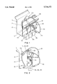
- FIG. 1 is an oblique view of the spinning device of the invention.
- FIG. 2 is a side view of the spinning device of the invention.
- FIGS. 1 and 2 One favoured embodiment of the invention is described as an illustration in FIGS. 1 and 2 whereby FIG. 1 displays a look at an angle of a spinning device according to this invention and FIG. 2 provides a side view.
- FIGS. 1 and 2 represents one of many possible forms of the spinning device according to this invention.
- FIG. 1 shows the nature of a spinning device (1) according to this invention. It comprises a container 2 for the precipitation bath (not shown), for example three spinning pumps 10, 20 and 30, which provide the feed pipe lines 11, 21 and 31 with spinning solution. Spinnerets 12, 22 and 32 are located at the end of each feed pipe line from which the filaments (not illustrated) emerge into the precipitation bath.
- the feed pipe lines can be swivelled around one joint 13, 23 and 33 respectively and are bent to alleviate the swivelling out from the container. The bend, however, is not sufficient to permit full swivelling-out with respect to a deeper container like that shown in FIG. 2.
- the joints themselves are arranged movable in the vertical and horizontal direction and that, in the case of the embodiments given preference in FIGS. 1 and 2, around one pivot 14, 24 and 34 (can only be seen in FIG. 2) respectively, which is attached to the longitudinal wall of container 2.
- Feed pipe line 11 together with the necessary spinneret 12 is in the position adopted when the spinning device is in operation i.e. when spinning.
- the spinneret is located, as can be seen from FIG. 2, right at the bottom of container 2 which guarantees a long immersion path of the emerging filaments.
- the feed pipe line will first of all be slightly raised, which is illustrated in the figures with respect to feed pipe line 21 including spinneret 22.
- the joint 23 belonging to the feed pipe line 21 is swung upwards round pivot 24 by this movement.
Landscapes
- Engineering & Computer Science (AREA)
- Mechanical Engineering (AREA)
- Textile Engineering (AREA)
- Spinning Methods And Devices For Manufacturing Artificial Fibers (AREA)
- Artificial Filaments (AREA)
Abstract
A spinning device for the production of man-made fibers, in particular of cellulose regenerated fibers, including at least one spinning pump, at least one feed pipe line, at least one spinneret and a bath-like container for the precipitation bath whereby the feed pipe lines can be swivelled around at least one joint at any one time which is characterized in that the joint is movable in substantially horizontal and vertical direction. In one embodiment of the device the joint can be swivelled around one pivot respectively. With the device according to this invention, it is possible to simply swivel the spinnerets out of a deeper container which is required to enable a longer immersion path of the fibers.
Description
The invention refers to a spinning device for the production of man-made fibres, particularly cellulose regenerated fibres. Well-known spinning devices, for the production of cellulose regenerated fibres for example, operate on the principle that a viscous spinning solution or spinning mass e.g. viscose is pressed by means of pumps through a spinneret into an aqueous precipitation bath containing chemical additives. A filament of regenerated cellulose is thereby formed as a result of viscose decomposition which is drawn off via rollers or something similar whereby stretching of the filaments generally takes place in the precipitation bath.
An example of a spinning device built in the traditional fashion is illustrated in "Man-Made Fibres Using the Viscose Process" by K. GOTZE, 3rd Edition, Volume 2, Springer Publications Berlin/Heidelberg/New York (1967) on p. 850. The device is made of a bath-like container on which spinning pumps are arranged in the longitudinal direction which transport the spinning solution (viscose) via feed pipe lines to a spinneret. The bath-like container contains the precipitation bath into which the spinneret is dipped whereby the openings of the spinneret are aligned so that the fibres emerging from the spinneret emerge in a substantially vertical direction. The feed pipe lines for the spinning solutions are pivoted around joints which means that the spinneret can be swivelled out of the container during maintenance work, or when disconnecting the line.
The development of new types of fibres with special properties has meant that numerous parameters in the spinning process for the production of cellulose regenerated fibres have been changed. Amongst these parameters one can for example count the retention time of the filament in the precipitation bath which is adjusted by the take-up speed, and in particular by the immersion path of the filaments in the precipitation bath. In this way, an effort was made in particular to extend the immersion path.
The immersion path can be extended if, for example, the emerging filament is not drawn off substantially vertically but rather emerges from the spinneret in more of a horizontal direction by using a flatter container and is drawn off horizontally thereby being immersed in the precipitation bath for a longer distance in this container.
By this measure the immersion path is extended, however, the use of a flat container and the drawing-off of the filament in the horizontal direction on the one hand demands a considerably greater amount of space and on the other hand, the filament has to be led around rollers, or a similar device, which has a negative impact on the fibre properties.
A second possibility to extend the immersion path is to design the container with the precipitation bath deeper with respect to a drawing-off in vertical direction. Until now, this could only be achieved to the extent that it was still possible to swivel the spinneret out from the deeper container according to the length of the feed pipe line. Since in order to effectively be able to bring the spinneret into the deep parts of the container, which is necessary to achieve a longer immersion path, it is also necessary to correspondingly extend the feed pipe line. However, it is not possible to swivel the spinneret out of the container once a feed pipe line of a certain length is used. This can only be done once apparatus parts obstructing the swivelling process have been removed.
It is an object of the present invention to arrange a spinning device on the basis of the principle described above so as to make it possible to provide a deeper container for the precipitation bath so that the immersion path can be prolonged and, at the same time, the spinneret can be easily swivelled out of the container.
According to this invention this object is reached by means of a spinning device for the manufacture of man-made fibres, and in particular cellulose regenerated fibres, comprising at least one spinning pump, at least one feed pipe line, at least one spinneret and one bath-like container for the precipitation bath whereby the at least one feed pipe line can be swivelled around one joint respectively, which is characterised in that the joint is arranged movable in substantially vertical and horizontal direction.
The arrangement according to this invention that the joints, around which the feed pipe lines for the spinning solution can be swivelled, are also movable, can very simply produce a considerable advantage when handling the spinning device. The feed pipe lines can be easily swivelled out even of a deep container which means that maintenance work, such as for example the exchange of the spinneret or a similar operation, can be performed more swiftly and easily and yet all the advantages of a long immersion path of the filament in the precipitation bath are upheld.
One particularly effective embodiment of the spinning device according to the invention is characterized in that the joints can be swivelled around one pivot, respectively. This particular arrangement makes it especially easy to swivel the feed pipe lines out of the container. The pivot, around which the joints are stored, can for example be located on the longitudinal wall of the container, however, from the point of view of construction, many other embodiments of the invention are possible.
A preferred embodiment of the invention is illustrated in the appended drawings, in which
FIG. 1 is an oblique view of the spinning device of the invention, and
FIG. 2 is a side view of the spinning device of the invention.
One favoured embodiment of the invention is described as an illustration in FIGS. 1 and 2 whereby FIG. 1 displays a look at an angle of a spinning device according to this invention and FIG. 2 provides a side view.
It should be noted that the embodiment of the invention shown in FIGS. 1 and 2 represents one of many possible forms of the spinning device according to this invention.
FIG. 1 shows the nature of a spinning device (1) according to this invention. It comprises a container 2 for the precipitation bath (not shown), for example three spinning pumps 10, 20 and 30, which provide the feed pipe lines 11, 21 and 31 with spinning solution. Spinnerets 12, 22 and 32 are located at the end of each feed pipe line from which the filaments (not illustrated) emerge into the precipitation bath. The feed pipe lines can be swivelled around one joint 13, 23 and 33 respectively and are bent to alleviate the swivelling out from the container. The bend, however, is not sufficient to permit full swivelling-out with respect to a deeper container like that shown in FIG. 2.
For this reason, according to the invention it is provided that the joints themselves are arranged movable in the vertical and horizontal direction and that, in the case of the embodiments given preference in FIGS. 1 and 2, around one pivot 14, 24 and 34 (can only be seen in FIG. 2) respectively, which is attached to the longitudinal wall of container 2.
The principle of the invention will now be illustrated substantially by the different positions of the feed pipe lines 11, 21 and 31. Feed pipe line 11 together with the necessary spinneret 12 is in the position adopted when the spinning device is in operation i.e. when spinning. The spinneret is located, as can be seen from FIG. 2, right at the bottom of container 2 which guarantees a long immersion path of the emerging filaments.
If the spinneret now has to be swivelled out of the container due to an interruption in the spinning operation for example due to maintenance work, the feed pipe line will first of all be slightly raised, which is illustrated in the figures with respect to feed pipe line 21 including spinneret 22. The joint 23 belonging to the feed pipe line 21 is swung upwards round pivot 24 by this movement.
In a second step it is now simple to swivel the feed pipe line completely out of the container as is illustrated with respect to feed pipe line 31 with the necessary spinneret 32. The joint 33 belonging to feed pipe line 31 is in turn swung downwards.
During the entire swivel operation no other apparatus part is touched by the feed pipe line or by the spinneret so that this process can be completed very easily. Of course, in reality, the swivel operation represents a continuous process. The process was broken down into steps to better illustrate the invention on the basis of FIGS. 1 and 2.
It is quite clear that without the arrangement of the itself movable joint 13, 23, 33 according to this invention, it would not be possible to swivel the feed pipe lines out of a deep container like for example the one shown in the figures. The invention, therefore, incorporates a number of process simplifications when producing spinning filaments with modified fibre properties due to the prolonged immersion path.
Claims (5)
1. A spinning device for the production of man-made fibers, in particular cellulose regenerated fibres, comprising at least one spinning pump, at least one feed pipe line, at least one spinneret, a container for a precipitation bath whereby the feed pipe line can be swivelled around at least one joint wherein the joint is arranged movable in substantially horizontal and vertical direction.
2. Spinning device according to claim 1 wherein the joint can be swivelled around one pivot.
3. Spinning device according to claim 2 wherein the pivot is located on a longitudinal wall of the container.
4. Spinning device according to claim 1 having a plurality of feed pipe lines, a plurality of joints and a plurality of pivots, wherein each feed pipe line can be swiveled around a respective joint and wherein each joint can be swiveled around a respective pivot.
5. Spinning device according to claim 4, wherein each pivot is located on a longitudinal wall of the container.
Applications Claiming Priority (3)
| Application Number | Priority Date | Filing Date | Title |
|---|---|---|---|
| AT0107194A AT400849B (en) | 1994-05-26 | 1994-05-26 | SPINNING DEVICE WITH MOVABLE JOINT |
| ATA1071/94 | 1994-05-26 | ||
| PCT/AT1995/000097 WO1995033087A1 (en) | 1994-05-26 | 1995-05-22 | Spinning device with a mobile joint |
Publications (1)
| Publication Number | Publication Date |
|---|---|
| US5714172A true US5714172A (en) | 1998-02-03 |
Family
ID=3505980
Family Applications (1)
| Application Number | Title | Priority Date | Filing Date |
|---|---|---|---|
| US08/581,540 Expired - Fee Related US5714172A (en) | 1994-05-26 | 1995-05-22 | Spinning device with movable joint |
Country Status (9)
| Country | Link |
|---|---|
| US (1) | US5714172A (en) |
| EP (1) | EP0711364B1 (en) |
| JP (1) | JPH09501475A (en) |
| CN (1) | CN1129019A (en) |
| AT (1) | AT400849B (en) |
| AU (1) | AU2518295A (en) |
| BR (1) | BR9506246A (en) |
| DE (1) | DE59508510D1 (en) |
| WO (1) | WO1995033087A1 (en) |
Families Citing this family (2)
| Publication number | Priority date | Publication date | Assignee | Title |
|---|---|---|---|---|
| AT411364B (en) * | 1999-07-27 | 2003-12-29 | Chemiefaser Lenzing Ag | DEVICE FOR PRODUCING VISCOSE STAPLE FIBERS |
| DE102008002903A1 (en) | 2008-06-24 | 2010-01-14 | Tutech Innovation Gmbh | Method for braking an internal combustion engine |
Citations (9)
| Publication number | Priority date | Publication date | Assignee | Title |
|---|---|---|---|---|
| US2198448A (en) * | 1937-03-18 | 1940-04-23 | Tubize Chatillon Corp | Continuous filament formation |
| US2243116A (en) * | 1936-03-09 | 1941-05-27 | American Bemberg Corp | Apparatus for use in manufacturing artificial filaments |
| US2533103A (en) * | 1948-05-07 | 1950-12-05 | Courtaulds Ltd | Apparatus for the liquid treatment of threads |
| US2586970A (en) * | 1948-12-18 | 1952-02-26 | American Viscose Corp | Apparatus for spinning artificial filaments |
| DE836538C (en) * | 1950-01-08 | 1952-04-15 | Phrix Werke Ag | Storage of the spinning pipes on rayon and rayon spinning machines |
| US2611925A (en) * | 1948-11-23 | 1952-09-30 | American Viscose Corp | Apparatus for producing high tenacity artificial yarn and cord |
| US2624070A (en) * | 1951-06-04 | 1953-01-06 | American Viscose Corp | Spinning or extrusion apparatus |
| US2803851A (en) * | 1953-03-13 | 1957-08-27 | American Viscose Corp | Spinneret assembly |
| US2920346A (en) * | 1957-08-09 | 1960-01-12 | Jori Luciano | Thread stretching device for wet spinning more particularly of viscose rayon |
-
1994
- 1994-05-26 AT AT0107194A patent/AT400849B/en not_active IP Right Cessation
-
1995
- 1995-05-22 WO PCT/AT1995/000097 patent/WO1995033087A1/en active IP Right Grant
- 1995-05-22 DE DE59508510T patent/DE59508510D1/en not_active Expired - Fee Related
- 1995-05-22 CN CN95190468.XA patent/CN1129019A/en active Pending
- 1995-05-22 JP JP8500060A patent/JPH09501475A/en active Pending
- 1995-05-22 BR BR9506246A patent/BR9506246A/en not_active Application Discontinuation
- 1995-05-22 AU AU25182/95A patent/AU2518295A/en not_active Abandoned
- 1995-05-22 EP EP95919269A patent/EP0711364B1/en not_active Expired - Lifetime
- 1995-05-22 US US08/581,540 patent/US5714172A/en not_active Expired - Fee Related
Patent Citations (9)
| Publication number | Priority date | Publication date | Assignee | Title |
|---|---|---|---|---|
| US2243116A (en) * | 1936-03-09 | 1941-05-27 | American Bemberg Corp | Apparatus for use in manufacturing artificial filaments |
| US2198448A (en) * | 1937-03-18 | 1940-04-23 | Tubize Chatillon Corp | Continuous filament formation |
| US2533103A (en) * | 1948-05-07 | 1950-12-05 | Courtaulds Ltd | Apparatus for the liquid treatment of threads |
| US2611925A (en) * | 1948-11-23 | 1952-09-30 | American Viscose Corp | Apparatus for producing high tenacity artificial yarn and cord |
| US2586970A (en) * | 1948-12-18 | 1952-02-26 | American Viscose Corp | Apparatus for spinning artificial filaments |
| DE836538C (en) * | 1950-01-08 | 1952-04-15 | Phrix Werke Ag | Storage of the spinning pipes on rayon and rayon spinning machines |
| US2624070A (en) * | 1951-06-04 | 1953-01-06 | American Viscose Corp | Spinning or extrusion apparatus |
| US2803851A (en) * | 1953-03-13 | 1957-08-27 | American Viscose Corp | Spinneret assembly |
| US2920346A (en) * | 1957-08-09 | 1960-01-12 | Jori Luciano | Thread stretching device for wet spinning more particularly of viscose rayon |
Non-Patent Citations (2)
| Title |
|---|
| K. G o tze, Man Made Fibres Using the Viscose Process vol. 2, 3rd Edition, Springer Publications, Berlin/Heidelberg/New York (1967) pp. 847 853. * |
| K. Gotze, "Man Made Fibres Using the Viscose Process" vol. 2, 3rd Edition, Springer Publications, Berlin/Heidelberg/New York (1967) pp. 847-853. |
Also Published As
| Publication number | Publication date |
|---|---|
| EP0711364A1 (en) | 1996-05-15 |
| ATA107194A (en) | 1995-08-15 |
| BR9506246A (en) | 1997-08-12 |
| WO1995033087A1 (en) | 1995-12-07 |
| CN1129019A (en) | 1996-08-14 |
| EP0711364B1 (en) | 2000-06-28 |
| AU2518295A (en) | 1995-12-21 |
| AT400849B (en) | 1996-03-25 |
| JPH09501475A (en) | 1997-02-10 |
| DE59508510D1 (en) | 2000-08-03 |
Similar Documents
| Publication | Publication Date | Title |
|---|---|---|
| FI963269A0 (en) | spinner | |
| US5714172A (en) | Spinning device with movable joint | |
| US2241304A (en) | Apparatus for the production of artificial threads | |
| CN205821552U (en) | Spin finishing system | |
| KR100494267B1 (en) | Method and device for extruding a continuous moulded body | |
| KR100550686B1 (en) | Method and device for producing continuous moulded bodies | |
| CN107354591A (en) | The wet-laying mechanism of continuous yarn non-woven fabrics is prepared based on wet spinning technology | |
| CN216105328U (en) | Durable wire guiding device | |
| CN205974761U (en) | Chemical filament device that oils | |
| CN2825693Y (en) | Yarn-dyeing bobbin structure | |
| CN206872163U (en) | A kind of pushing cylinder structure of automatic production line steel wire storage device guide frame | |
| CN210287613U (en) | Fiber spinning and bundling device | |
| CN208899078U (en) | A kind of terylene multiple roll drafting system | |
| CN112708953B (en) | Spinning coagulating bath device | |
| US2852808A (en) | Apparatus for manufacture or treatment of artificial filamentary materials | |
| CN112030294A (en) | Prevent weaving yarn that splits | |
| CN213708559U (en) | Novel hollow cleaning needle | |
| CN105821489B (en) | A kind of textile melts dynamic mixer | |
| CN2856071Y (en) | Continuous spinning machine for acrylic fibers filament | |
| CN215404698U (en) | Spinning guiding device | |
| CN108754651B (en) | Unmanned automatic production equipment of wool-like chinlon filaments | |
| CN204676232U (en) | Chemical-fibres filaments after-treatment device | |
| CN213232618U (en) | Novel humidifying device of flax wet spinning frame | |
| CN218454244U (en) | False twisting device that cooling effect is good | |
| CN210657280U (en) | Yarn suction device of spinning frame |
Legal Events
| Date | Code | Title | Description |
|---|---|---|---|
| AS | Assignment |
Owner name: LENZING AKTIENGESELLSCHAFT, AUSTRIA Free format text: ASSIGNMENT OF ASSIGNORS INTEREST;ASSIGNOR:SCHONBERG, ANTON;REEL/FRAME:008486/0842 Effective date: 19970421 |
|
| FEPP | Fee payment procedure |
Free format text: PAYOR NUMBER ASSIGNED (ORIGINAL EVENT CODE: ASPN); ENTITY STATUS OF PATENT OWNER: LARGE ENTITY |
|
| REMI | Maintenance fee reminder mailed | ||
| LAPS | Lapse for failure to pay maintenance fees | ||
| STCH | Information on status: patent discontinuation |
Free format text: PATENT EXPIRED DUE TO NONPAYMENT OF MAINTENANCE FEES UNDER 37 CFR 1.362 |
|
| FP | Lapsed due to failure to pay maintenance fee |
Effective date: 20020203 |