US5713541A - Electromagnetic interference detection system for mass transit vehicles with electronic propulsion - Google Patents
Electromagnetic interference detection system for mass transit vehicles with electronic propulsion Download PDFInfo
- Publication number
- US5713541A US5713541A US08/776,963 US77696397A US5713541A US 5713541 A US5713541 A US 5713541A US 77696397 A US77696397 A US 77696397A US 5713541 A US5713541 A US 5713541A
- Authority
- US
- United States
- Prior art keywords
- amplitude
- signal
- output
- set forth
- interval
- Prior art date
- Legal status (The legal status is an assumption and is not a legal conclusion. Google has not performed a legal analysis and makes no representation as to the accuracy of the status listed.)
- Expired - Fee Related
Links
- 238000001514 detection method Methods 0.000 title claims abstract description 10
- 230000004044 response Effects 0.000 claims description 41
- 230000011664 signaling Effects 0.000 claims description 18
- 238000000034 method Methods 0.000 claims description 15
- 239000003990 capacitor Substances 0.000 claims description 9
- 230000004936 stimulating effect Effects 0.000 claims description 6
- 238000001228 spectrum Methods 0.000 claims description 4
- 238000012544 monitoring process Methods 0.000 claims description 3
- 230000000638 stimulation Effects 0.000 claims description 3
- 238000012360 testing method Methods 0.000 description 9
- 238000012795 verification Methods 0.000 description 9
- 238000001914 filtration Methods 0.000 description 8
- 230000006870 function Effects 0.000 description 7
- 238000004804 winding Methods 0.000 description 3
- 230000004075 alteration Effects 0.000 description 2
- 230000008859 change Effects 0.000 description 2
- 238000006243 chemical reaction Methods 0.000 description 2
- 238000010586 diagram Methods 0.000 description 2
- 230000000694 effects Effects 0.000 description 2
- 238000002955 isolation Methods 0.000 description 2
- 238000012986 modification Methods 0.000 description 2
- 230000004048 modification Effects 0.000 description 2
- 230000009467 reduction Effects 0.000 description 2
- 230000002159 abnormal effect Effects 0.000 description 1
- 230000009471 action Effects 0.000 description 1
- 238000007599 discharging Methods 0.000 description 1
- 230000000977 initiatory effect Effects 0.000 description 1
- 230000002452 interceptive effect Effects 0.000 description 1
- 238000011084 recovery Methods 0.000 description 1
- 238000006467 substitution reaction Methods 0.000 description 1
- 230000002123 temporal effect Effects 0.000 description 1
- 230000000007 visual effect Effects 0.000 description 1
Images


Classifications
-
- B—PERFORMING OPERATIONS; TRANSPORTING
- B60—VEHICLES IN GENERAL
- B60L—PROPULSION OF ELECTRICALLY-PROPELLED VEHICLES; SUPPLYING ELECTRIC POWER FOR AUXILIARY EQUIPMENT OF ELECTRICALLY-PROPELLED VEHICLES; ELECTRODYNAMIC BRAKE SYSTEMS FOR VEHICLES IN GENERAL; MAGNETIC SUSPENSION OR LEVITATION FOR VEHICLES; MONITORING OPERATING VARIABLES OF ELECTRICALLY-PROPELLED VEHICLES; ELECTRIC SAFETY DEVICES FOR ELECTRICALLY-PROPELLED VEHICLES
- B60L9/00—Electric propulsion with power supply external to the vehicle
- B60L9/005—Interference suppression
-
- B—PERFORMING OPERATIONS; TRANSPORTING
- B60—VEHICLES IN GENERAL
- B60L—PROPULSION OF ELECTRICALLY-PROPELLED VEHICLES; SUPPLYING ELECTRIC POWER FOR AUXILIARY EQUIPMENT OF ELECTRICALLY-PROPELLED VEHICLES; ELECTRODYNAMIC BRAKE SYSTEMS FOR VEHICLES IN GENERAL; MAGNETIC SUSPENSION OR LEVITATION FOR VEHICLES; MONITORING OPERATING VARIABLES OF ELECTRICALLY-PROPELLED VEHICLES; ELECTRIC SAFETY DEVICES FOR ELECTRICALLY-PROPELLED VEHICLES
- B60L9/00—Electric propulsion with power supply external to the vehicle
- B60L9/16—Electric propulsion with power supply external to the vehicle using AC induction motors
- B60L9/18—Electric propulsion with power supply external to the vehicle using AC induction motors fed from DC supply lines
- B60L9/22—Electric propulsion with power supply external to the vehicle using AC induction motors fed from DC supply lines polyphase motors
-
- B—PERFORMING OPERATIONS; TRANSPORTING
- B60—VEHICLES IN GENERAL
- B60L—PROPULSION OF ELECTRICALLY-PROPELLED VEHICLES; SUPPLYING ELECTRIC POWER FOR AUXILIARY EQUIPMENT OF ELECTRICALLY-PROPELLED VEHICLES; ELECTRODYNAMIC BRAKE SYSTEMS FOR VEHICLES IN GENERAL; MAGNETIC SUSPENSION OR LEVITATION FOR VEHICLES; MONITORING OPERATING VARIABLES OF ELECTRICALLY-PROPELLED VEHICLES; ELECTRIC SAFETY DEVICES FOR ELECTRICALLY-PROPELLED VEHICLES
- B60L2200/00—Type of vehicles
- B60L2200/26—Rail vehicles
Definitions
- the present invention relates to mass transit vehicles powered from external sources of electrical power and, more particularly, to systems for detecting electromagnetic interference during the operation of mass transit vehicles.
- An electrically powered mass transit vehicle typically includes a propulsion system connected to a direct current (DC) motor or alternating current (AC) motor for propelling the vehicle on running rails.
- the propulsion system is often driven by a source of DC electrical power supplied from a remote source via a supply line, such as a power rail or an overhead power line.
- the DC power is often supplied at a relatively high voltage to minimize power loss associated with resistive drops along the length of the supply line.
- a return path for the DC electric power is provided via the running rails. It is to be appreciated that the DC electrical power, and more specifically, the DC current, provided to the vehicle via the supply line also flows in the running rails.
- running rails it is common to use the running rails to also provide AC control signals to track signaling equipment, e.g., wayside aspect lights, associated with the rail or track system. These AC control signals are provided at predetermined frequencies, e.g., 60 Hz and 100 Hz. To provide for operation of the track signaling equipment during operation of the vehicle, these AC control signals are superimposed on DC current in the running rails.
- track signaling equipment e.g., wayside aspect lights
- the electric motor of a mass transit vehicle is typically designed for variable speed operation at voltages and currents other than provided by the supply line. To accomplish variable speed operation, it is common to switchably control the power supplied to the motor.
- the propulsion system includes a DC-DC converter for converting supplied DC to a DC useable by the motor.
- the propulsion system includes a DC-AC inverter for changing the supplied DC to an AC useable by the motor. In operation, the DC-DC converter or the DC-AC inverter controllably switches power from the supply line to the motor as a function of the desired operating characteristics thereof.
- EMI Electromagnetic Interference
- EMI may contain frequency components in the range of the AC control signals for the track signaling equipment associated with the vehicle. Accordingly, there are concerns that such EMI may cause unintended operation of or undesirable interference with the track signaling equipment.
- standard propulsion systems include line filters for absorbing significant line current frequencies produced by the DC-DC converter or the DC-AC inverter and, more specifically, for absorbing line current frequencies in the range of control signals for the track signaling equipment, i.e., 60 Hz and 100 Hz. In this manner, the effect of EMI on the DC current by the operation of the DC-DC converter or DC-AC inverter is reduced.
- Line filters are typically designed to provide filtration of noise within certain established levels, e.g., without limitation, amplitude, duration and/or frequency. As a result, noise outside the established levels will not be adequately filtered and will be conducted on the supply line. Moreover, if electrical components, e.g., capacitors, associated with the line filter fail or change value with age, the effective filtration characteristics of the line filter are changed and noise normally filtered thereby appears on the DC current. As discussed above, this is a particular problem where the unfiltered noise has frequency components in common with the track signaling equipment, i.e., 60 Hz and 100 Hz.
- DC direct current
- AC alternating current
- adjusting the power output includes: maintaining the power output to the electric motor at the first level in response to the AC signal being less than a first amplitude for a first interval of time; reducing the power output to the electric motor from the first level to a second level if the AC signal has an amplitude greater than the first amplitude for the first interval of time; and withholding electrical power from the motor if the AC signal has an amplitude greater than a second amplitude, greater than the first amplitude, for the first interval of time. If the AC signal has an amplitude greater than the second amplitude for a second interval of time, greater than the first interval, the vehicle is isolated from the supply line. The isolation of the vehicle from the supply line terminates the conversion of electrical power and the providing thereof to the electric motor.
- the method further includes stimulating a current transducer with an alternating current.
- the stimulating current causes the transducer to produce an output signal which is detected.
- At least one of the frequency, amplitude and duration of the output signal is determined and power output is provided to the electric motor as a function of the at least one of the frequency, amplitude and duration of the output signal.
- the electromagnetic detection and control apparatus includes a means for converting electrical power supplied to the vehicle via a supply line to a selectable power output and a means for providing the power output to an electric motor in the vehicle.
- a means is provided for monitoring the supply line for an alternating current (AC) signal appearing thereon and for determining one of an amplitude and duration thereof.
- the apparatus also includes a means for adjusting the power output as a function of at least one of the amplitude and duration of the AC signal.
- the apparatus also includes a means for maintaining the power output to the electric motor at a first level in response to the AC signal being less than a first amplitude for a first interval of time; a means for reducing the power output to the electric motor from the first level to a second level in response to the AC signal being greater than the first amplitude for the first interval of time; and a means for withholding the power output from the electric motor in response to the AC signal being greater than a second amplitude for the first interval of time, wherein the second amplitude is greater than the first amplitude.
- the apparatus further includes a means for isolating the vehicle from the supply line in response to the AC signal being greater than the second amplitude for a second interval of time, wherein the second interval is greater than the first interval.
- the apparatus includes means for stimulating a current transducer with an alternating current and a means for detecting an output signal of the transducer in response to the stimulation.
- a means is provided for determining at least one of a frequency, amplitude and duration of the output signal and for enabling the providing means to provide power output to the electric motor as a function of the at least one of the frequency, amplitude and duration of the output signal.
- FIG. 1 is a plan view of an electrically powered mass transit vehicle in accordance with the prior art
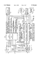
- FIG. 2 is a block diagram of an electromagnetic interference detection system of the present invention connected to various systems and subsystems of the vehicle shown in FIG. 1;
- FIG. 3 is a block diagram of the EMI processor shown in FIG. 2.
- a prior art electrically powered mass transit vehicle 2 includes a forward disposed alternating current (AC) electric motor 4A and rearward disposed AC motor 4B for providing motive force to front and rear wheels 6A and 6B, respectively, so as to propel vehicle 2 along a running rail 8.
- AC alternating current
- the vehicle 2 has front and rear wheels (not shown) disposed on an opposite side thereof and in contact with another rail.
- the other wheels can have dedicated AC motors for providing motive force thereto or may be powered from AC motors 4A and 4B.
- AC motors 4A and 4B providing motive force to wheels 6A and 6B.
- a pantograph 10 conducts direct current (DC) electric power from a supply line 12 to the vehicle 2.
- DC direct current
- DC electric power conducted by pantograph 10 is converted to AC power, by apparatus to be hereinafter described, provided to AC motors 4A and 4B and returned to ground through contact with the running rail 8.
- the AC motors 4A and 4B convert the AC power provided thereto to motive force of sufficient extent to propel vehicle 2 along rail 8.
- the vehicle 2 could alternatively be equipped with DC motors.
- vehicle 2 includes “A" and “B" propulsion systems 14A and 14B having their respective inputs connected to pantograph 10.
- the outputs of the propulsion systems 14A and 14B are connected to respective AC motors 4A and 4B.
- the propulsion systems 14A and 14B convert DC electric power supplied thereto to AC electric power useable by AC motors 4A and 4B.
- the propulsion systems 14A and 14B are shown as being connected to respective AC motors 4A and 4B.
- propulsion systems 14A and 14B are also connected to AC motors associated with the respective front and rear wheels on the opposite side of vehicle 2 for providing power thereto.
- propulsion system 14A powering AC motor 4A is to be understood as also providing power, in parallel, to the motor associated with the other front wheel. Similar comments apply in respect of propulsion system 14B and the motors associated with the rear wheels of vehicle 2.
- Vehicle 2 also includes an auxiliary power supply 16 having an input connected to pantograph 10 and an output connected to vehicle subsystems 18, such as air conditioners, fans, lights and the like.
- the auxiliary power supply 16 converts supplied DC electric power to AC power useable by the vehicle subsystems 18.
- the propulsion systems 14A and 14B and the auxiliary power supply 16 are grounded to rail 8.
- propulsion systems 14A and 14B controllably switch power from supply line 12 to AC motors 4A and 4B at a level suitable to propel the vehicle 2 at a selectable rate. In the event one of the propulsion systems 14A and 14B is inoperative, however, the vehicle is operable from the remaining propulsion system, albeit at a reduced vehicle performance.
- Track signaling equipment is often utilized in conjunction with the vehicle 2 to provide suitable warning and control signals concomitant with the operation thereof.
- This signaling equipment obtains control signals for the selective operation thereof from the running rails 8.
- These control signals often take the form of alternating current (AC) signals superimposed on the DC current in the running rails 8 at predetermined amplitudes and frequencies, such as, without limitation, 60 Hz, 100 Hz and audio frequencies, for predetermined intervals.
- AC alternating current
- the propulsion systems 14A and 14B switching relatively significant power levels at variable frequencies, produce significant AC noise on the DC current. This AC noise is commonly referred to as Electromagnetic Interference (EMI).
- EMI Electromagnetic Interference
- auxiliary power supply 16 switching lower power levels at a constant operating frequency also produces EMI on the DC current, albeit to a lesser extent than the propulsion systems 14A and 14B.
- This EMI often contains components with amplitudes, frequencies and durations in common with the control signals for the track signaling equipment. Because such EMI could potentially interfere with the operation of track signaling equipment, prior art propulsion systems are equipped with input filters, typically an inductor-capacitor circuit, for filtering EMI appearing on the DC current. It is to be appreciated that the input filters may include more than one inductor and more than one capacitor to achieve a desired level of filtration.
- the system of the present invention includes a filter verification circuit 20A and 20B connected to a respective propulsion system 14A and 14B for verifying that the capacitor(s) of the input filter in an associated propulsion system will provide a desired level of filtration.
- each filter verification circuit measures the time needed to selectively charge and/or discharge the capacitor(s) of the corresponding input filter between desired voltage levels during, for example, a period of vehicle inactivity. Utilizing the measured charging and/or discharging time, the filter verification circuit calculates if the filter capacitance value is within acceptable limits for filtering EMI below an acceptable noise limit for the output power to be provided by the associated propulsion system.
- the filter capacitance value is calculated to be below certain predetermined acceptable limits, the output of the propulsion system is reduced to a level wherein EMI produced thereby is normally below the acceptable EMI noise limit for the actual filter capacitance. If additional capacitors of the input filter fail or change value with age, the output of the propulsion system is reduced accordingly. If the filter verification circuit determines that the actual filter capacitance is below a predetermined lower limit, the filter verification circuit shuts down the associated propulsion system. The filter verification circuit also verifies integrity of one or more fuses associated with one or more capacitors or capacitor banks of the input filter.
- the filter verification circuit determines that one or more fuses are open, the filter verification circuit selectively reduces or adjusts the power output of the associated propulsion system so that the output of the propulsion system is reduced to a level wherein EMI produced thereby is normally below the acceptable EMI noise limit for the available filter capacitance. In this manner, the output of the propulsion system is adjusted so that EMI produced thereby will normally be below a limit that could potentially interfere with the operation of track signaling equipment.
- each propulsion system is designed to provide adequate filtration so that typical levels of EMI produced by the propulsion system do not interfere with the operation of track signaling equipment.
- each filter verification circuit (20A and 20B) is designed to reduce the output of the associated propulsion system as a function of the available filter capacitance.
- the propulsion systems may, under abnormal conditions, produce atypical levels of EMI that would not be adequately filtered by the available filter capacitance to avoid interfering with the operation of the track signaling system.
- partial or complete failure of an input filter during operation of the vehicle could produce EMI which would not be adequately filtered.
- the present invention includes an EMI detector 24 for detecting EMI exceeding a selected amplitude for a selected duration and for adjusting the output of the propulsion system as a function of the detected EMI.
- the EMI detector 24 includes a current transducer 26 and an EMI processor 28, which is preferably microprocessor based and software driven.
- the current transducer 26, such as, without limitation, a transformer, has a means 30 disposed on the vehicle side of pantograph 10 for detecting AC signals, and more specifically EMI, appearing on the DC current.
- the means for detecting AC signals 30 has an output connected to an input of the EMI processor 28 for providing scaled representations of the detected EMI signals thereto.
- the EMI processor 28 monitors the scaled signals and measures one or more of the amplitude, frequency and duration of the AC signals on the supply line 12.
- the EMI processor 28 can measure one or more selected frequencies or a frequency spectrum utilizing, without limitation, Fast Fourier Transform (FFT), a digital filter or other similar techniques.
- FFT Fast Fourier Transform
- the EMI processor 28 if the amplitude of the scaled signals have an amplitude less than or equal to a first amplitude at a selected frequency, the EMI processor 28 outputs a condition 0 signal to the propulsion systems 14A and 14B which interpret the same as an indication that the detected EMI is within acceptable limits.
- the EMI processor 28 outputs a condition 0 signal to the propulsion systems 14A and 14B if the scaled signals have an amplitude in excess of the first amplitude at the selected frequency, wherein said amplitude has a duration less than or equal to a first interval of time.
- the propulsion systems 14A and 14B maintain output power to the motors 4A and 4B at a first level. It is to be appreciated that the first level could be established by an operator of the vehicle 2 or, in an attendantless, automated vehicle, by an intelligent vehicle controller.
- the EMI processor 28 If, however, the current transducer 26 detects scaled signals having an amplitude above the first amplitude at the selected frequency, and the first amplitude has a duration in excess of the first interval of time, the EMI processor 28 outputs a condition 1 signal to the propulsion systems 14A and 14B. Moreover, the EMI processor 28 outputs an "Excess EMI Detected" signal to an EMI Detector Annunciator 32. In response to receiving the condition 1 signal, the propulsion systems 14A and 14B reduce the power output to the motors 4A and 4B to a second level that is, for example, 50% of the first level.
- the EMI Detector Annunciator 32 In response to receiving the Excess EMI Detected signal, the EMI Detector Annunciator 32 provides an audio or visual indication that excessive EMI has been detected.
- the AC signals corresponding to the condition 1 signal event do not cause interference with the signaling equipment.
- the condition 1 signal event is selected to avoid having the AC signals increase in amplitude and/or duration to where a condition 2 or 3 signal, described hereinafter, is generated.
- the EMI processor 28 automatically recovers, and outputs a condition 0 signal to the propulsion system, in response to detecting, for a predetermined interval of time, scaled signals having at least one of an amplitude, frequency and duration not corresponding to the EMI processor 28 generating a condition 1 signal.
- the EMI processor outputs a condition 0 signal to the propulsion systems 14A and 14B.
- the propulsion systems 14A and 14B restore the output power to the first level. If restoring the power output to the first level produces EMI levels corresponding to the condition 1 signal event, the EMI processor 28 again outputs a condition 1 signal to the propulsion systems 14A and 14B. The outputting of a condition 1 signal for a predetermined interval followed by condition 0 signal continues until the EMI is within acceptable limits. In this manner, the output of the propulsion systems 14A and 14B are adjusted for temporal occurrences of EMI.
- the frequencies, amplitudes and durations of EMI corresponding to the EMI processor outputting a condition 1 signal are: 60 Hz, I>2.8 amps, t>1.0 second; and 100 Hz, I>0.75 amps, t>1.0 second.
- the frequencies, amplitudes and durations to be detected by the EMI processor 28 for generating a condition 1 signal, as well as for generating conditions 2 and 3 signals, discussed below, are selected to allow for proper operation of the signaling equipment without interference by EMI generated by the propulsion systems.
- the reduction of output power to 50% of desired output power is intended to reduce EMI noise to an acceptable level but other levels, or even more than one such level, of power reduction could be used.
- the EMI processor If current transducer 26 provides scaled signals having an amplitude in excess of a second amplitude, greater than the first amplitude, at the selected frequency, and the second amplitude has a duration in excess of the first interval of time, the EMI processor outputs a condition 2 signal to the propulsion systems 14A and 14B and outputs the Excess EMI Detected signal to the EMI Detector Annunciator 32. In response to receiving the condition 2 signal, the propulsion systems 14A and 14B withhold power from motors 4A and 4B, i.e., the output power is reduced to 0%.
- the frequencies, amplitudes and durations of EMI corresponding to the EMI processor 28 outputting a condition 2 signal are: 60 Hz, I>3.7 amps, t>1.0 second; and 100 Hz, I>1.0 amp, t>1.0 second.
- a resetting means provides the EMI processor 28 and propulsion systems 14A and 14B with a Propulsion Reset Trainline signal (shown in FIG. 2 as "RESET T/L") in response to an operator requested reset of the propulsion systems 14A and 14B in the presence of a brake request at zero vehicle speed.
- the operator may request up to three operator resets in this manner, whereafter, the propulsion systems 14A and 14B may only be reset by asserting a supervisory reset (not shown).
- the propulsion systems 14A and 14B provide the EMI processor 28 with "Level 2 Acknowledge” signals.
- the EMI processor 28 outputs a condition 3 signal to the propulsion systems 14A and 14B and outputs a "HSCB Trip" signal to a High Speed Circuit Breaker (HSCB) 34.
- the HSCB 34 is electrically disposed on the vehicle side of pantograph 10 so that DC electrical power provided to the vehicle 2 from the supply line 12 passes therethrough.
- the HSCB 34 opens and electrically isolates the vehicle 2, and more specifically, the propulsion systems 14A and 14B and the auxiliary power supply 16, from the supply line 12. In this manner, the EMI processor 28 ensures that the propulsion systems 14A and 14B and the auxiliary power supply 16 are eliminated as sources of EMI noise on the supply line 12.
- certain EMI levels are regarded as being of sufficient extent to merit immediate electrical isolation of the vehicle 2 from the supply line 12.
- the EMI processor 28 if the current transducer 26 provides scaled signals having an amplitude in excess of the second amplitude at the selected frequency, and the second amplitude has a duration in excess of a second interval of time, greater than the first interval of time, the EMI processor 28 outputs the condition 3 signal to the propulsion systems 14A and 14B and outputs the HSCB Trip signal to the HSCB 34.
- the EMI processor 28 outputs the Excess EMI Detected signal to the EMI Detector Annunciator 32.
- the HSCB 34 opens in response to the HSCB Trip signal, thereby electrically isolating the vehicle 2 from the supply line 12.
- the EMI processor 28 outputs a condition 3 signal and an HSCB Trip signal under two circumstances: firstly, if one or both Level 2 Acknowledge signals are not received by the EMI processor 28 in response to outputting a condition 2 signal; and secondly, if scaled signals are detected corresponding to excessive EMI.
- the amplitudes, durations and frequencies of EMI corresponding to EMI processor 28 outputting a condition 3 signal under the second circumstance are: 60 Hz, I>3.7 amps, t>1.5 seconds; and 100 Hz, I>1.0 amp, t>1.5 seconds.
- the resetting means (not shown) provides the EMI processor 28 and propulsion systems 14A and 14B with the Propulsion Reset Trainline signal.
- propulsion systems 14A and 14B and the HSCB 34 reset. The operator may request up to three resets in this manner, whereafter, the propulsion systems 14A and 14B and the HSCB 34 may be reset only by asserting a supervisory reset.
- the EMI processor 28 includes a software driven digital signal processor (DSP) 36, an analog data acquisition interface 38, a self test circuit 40, a memory system such as an EPROM 42, an input buffer 44 and an output buffer 46.
- the analog data acquisition interface 38 connects the output of the means for detecting AC signals 30 of the current transducer 26 to the DSP 36 and provides for conversion of analog data from the current transducer 26 to a digital equivalent useable by the DSP 36.
- the DSP 36 under the control of software stored in the EPROM 42, receives digital output from the analog data acquisition interface 38; provides control signals to the self test circuit 40 for testing the operation of the current transducer 26, in a manner to be described in greater detail hereinafter; receives digital input from the propulsion systems 14A and 14B and other vehicle subsystems through input buffer 44; and provides digital output to the propulsion systems 14A and 14B, the HSCB 34 and other vehicle subsystems through the output buffer 46.
- current transducer 26 includes a test winding 48, shown in phantom in FIG. 2, connected to the self test circuit 40.
- the DSP 36 causes the self test circuit 40 to energize the test winding 48 sufficiently to cause the means for detecting AC signals 30 of the current transducer 26 to experience AC noise of sufficient extent to cause the DSP 36 to detect scaled signals having, for example, an amplitude in excess of the second amplitude for a duration in excess of the first interval of time, i.e., a condition 2 signal event.
- the EMI processor 28 If, in response to energization of the test winding, signals having sufficient amplitude for a sufficient duration are not detected, the EMI processor 28 outputs a condition 2 signal to the propulsion systems 14A and 14B and outputs the EMI detector fault signal to EMI Detector Annunciator 32. In response to receiving the condition 2 signal, the propulsion systems 14A and 14B are rendered inoperative until reset as described above. If, however, the DSP 36 detects scaled signals corresponding to a condition 2 signal event, the EMI detector 24 is determined to be operational and a condition 0 signal is output to the propulsion systems 14A and 14B. In this manner, the operation of the EMI detector 24 can be verified.
- the present invention has been described above in conjunction with the detection of AC signals at a predetermined frequency. It is to be appreciated, however, that two or more predetermined frequencies could be detected. Moreover, AC signals operating over one or more frequency spectrums could also be detected using appropriate digital filtering techniques, such as FFT. Accordingly, the use above of a predetermined frequency to describe the operation of the present invention is not to be construed as limiting the invention. Furthermore, the individual frequencies or band of frequencies comprising the AC noise to be detected by the EMI detector could reside anywhere in a frequency spectrum wherein such AC noise is conductible onto the DC current.
- the EMI detector of the present invention is configurable to detect, without limitation, AC noise at one or more predetermined frequencies and/or AC noise over one or more continuous frequency bands or ranges at the same time.
- the frequencies or frequency bands to be monitored are adjustable by changing an EPROM, or by downloading new parameters or software into a RAM within the DSP.
- EMI detector 24 certain characteristics of the EMI detector 24, such as, without limitation, frequency, amplitude, duration, response time, recovery criteria, and the like, are adjustable by component substitution and/or software changes.
- the EMI detector 24 could be hardware and/or software modified to detect broadband AC signals and to respond thereto in the manner set forth above.
- the output power of the propulsion systems 14A and 14B could be independently adjusted to reduce EMI on the supply line 12.
- the EMI processor 28 could determine whether one of the propulsion systems 14A and 14B was a primary cause of EMI and selectively adjust the output power on that propulsion system to reduce the total EMI on the supply line 12 within acceptable levels, yet make no adjustment to the operation of the other propulsion system. It is intended that the invention be construed as including all such modifications and alterations insofar as they come within the scope of the appended claims or the equivalents thereof.
Landscapes
- Engineering & Computer Science (AREA)
- Life Sciences & Earth Sciences (AREA)
- Sustainable Development (AREA)
- Sustainable Energy (AREA)
- Power Engineering (AREA)
- Transportation (AREA)
- Mechanical Engineering (AREA)
- Electric Propulsion And Braking For Vehicles (AREA)
- Radar Systems Or Details Thereof (AREA)
- Near-Field Transmission Systems (AREA)
- Control Of Electric Motors In General (AREA)
- Cable Transmission Systems, Equalization Of Radio And Reduction Of Echo (AREA)
Priority Applications (1)
| Application Number | Priority Date | Filing Date | Title |
|---|---|---|---|
| US08/776,963 US5713541A (en) | 1995-06-13 | 1996-06-13 | Electromagnetic interference detection system for mass transit vehicles with electronic propulsion |
Applications Claiming Priority (3)
| Application Number | Priority Date | Filing Date | Title |
|---|---|---|---|
| US21995P | 1995-06-13 | 1995-06-13 | |
| PCT/US1996/010279 WO1996041728A1 (en) | 1995-06-13 | 1996-06-13 | Electromagnetic interference detection system for mass transit vehicles with electric propulsion |
| US08/776,963 US5713541A (en) | 1995-06-13 | 1996-06-13 | Electromagnetic interference detection system for mass transit vehicles with electronic propulsion |
Related Parent Applications (1)
| Application Number | Title | Priority Date | Filing Date |
|---|---|---|---|
| US60000219 Continuation | 1995-06-13 |
Publications (1)
| Publication Number | Publication Date |
|---|---|
| US5713541A true US5713541A (en) | 1998-02-03 |
Family
ID=21690464
Family Applications (1)
| Application Number | Title | Priority Date | Filing Date |
|---|---|---|---|
| US08/776,963 Expired - Fee Related US5713541A (en) | 1995-06-13 | 1996-06-13 | Electromagnetic interference detection system for mass transit vehicles with electronic propulsion |
Country Status (6)
| Country | Link |
|---|---|
| US (1) | US5713541A (de) |
| EP (1) | EP0777587B1 (de) |
| AT (1) | ATE251559T1 (de) |
| DE (1) | DE69630269D1 (de) |
| NO (1) | NO970649L (de) |
| WO (1) | WO1996041728A1 (de) |
Cited By (10)
| Publication number | Priority date | Publication date | Assignee | Title |
|---|---|---|---|---|
| US5902342A (en) * | 1997-03-27 | 1999-05-11 | Abb Daimler-Benz Transportation (North America) Inc. | Detection of vibration in an AC traction system |
| US6016016A (en) * | 1997-05-31 | 2000-01-18 | Luftansa Technik Ag | Voltage supply apparatus |
| US6321170B1 (en) * | 1997-11-14 | 2001-11-20 | Daimlerchrysler Rail Systems (Technology) Gmbh | Method for interference current and state monitoring in rail vehicles |
| US6496741B1 (en) | 1999-03-25 | 2002-12-17 | Gregory J. Whiffen | Static/dynamic control for optimizing a useful objective |
| US20050162876A1 (en) * | 2004-01-20 | 2005-07-28 | Loic Flandre | DC motor driving method for reducing adverse RF interferences and application to a vehicle lighting or signalling device |
| US20080143182A1 (en) * | 2006-12-15 | 2008-06-19 | Ravisekhar Nadimapalli Raju | Method and apparatus for generating electric power |
| WO2008029277A3 (en) * | 2006-06-30 | 2008-06-26 | Valeo Raytheon Systems Inc | Detecting signal interference in a vehicle system |
| US20120181391A1 (en) * | 2009-09-29 | 2012-07-19 | Siemens Aktiengesellschaft | Rail vehicle |
| CN112236332A (zh) * | 2018-06-07 | 2021-01-15 | 罗伯特·博世有限公司 | 用于机动车的控制器设备、机动车 |
| WO2025232155A1 (zh) * | 2024-05-10 | 2025-11-13 | 北京全路通信信号研究设计院集团有限公司 | 一种电磁环境的监测预警方法、装置、设备及介质 |
Citations (6)
| Publication number | Priority date | Publication date | Assignee | Title |
|---|---|---|---|---|
| US3634843A (en) * | 1968-10-14 | 1972-01-11 | Product Dev Services Inc | Circuit and method for detecting localized noise level changes and especially electromagnetic noise |
| US3776141A (en) * | 1971-02-20 | 1973-12-04 | E Gelhard | Transportation system particularly useful in hostile environments |
| US4168455A (en) * | 1976-07-05 | 1979-09-18 | Yamamoto Electric Industrial Co., Ltd. | Motor speed control system |
| US4202273A (en) * | 1976-09-13 | 1980-05-13 | The Furukawa Electric Co., Ltd. | Travelling object control system utilizing power control |
| US4970458A (en) * | 1989-05-08 | 1990-11-13 | Westinghouse Electric Corp. | AC voltage sensing for voltage regulators |
| US5021725A (en) * | 1988-11-29 | 1991-06-04 | Hitachi, Ltd. | Circuit arrangement for preventing inductive interference in an electric car |
Family Cites Families (2)
| Publication number | Priority date | Publication date | Assignee | Title |
|---|---|---|---|---|
| JPS57145503A (en) * | 1981-03-04 | 1982-09-08 | Hitachi Ltd | Controlling device of induction motor driven electric motor vehicle |
| DE3311874A1 (de) * | 1983-03-31 | 1984-10-04 | Siemens AG, 1000 Berlin und 8000 München | Verfahren und vorrichtung zum erfassen einer stoergroesse kleiner amplitude |
-
1996
- 1996-06-13 WO PCT/US1996/010279 patent/WO1996041728A1/en not_active Ceased
- 1996-06-13 US US08/776,963 patent/US5713541A/en not_active Expired - Fee Related
- 1996-06-13 DE DE69630269T patent/DE69630269D1/de not_active Expired - Lifetime
- 1996-06-13 AT AT96921598T patent/ATE251559T1/de not_active IP Right Cessation
- 1996-06-13 EP EP96921598A patent/EP0777587B1/de not_active Expired - Lifetime
-
1997
- 1997-02-12 NO NO970649A patent/NO970649L/no unknown
Patent Citations (6)
| Publication number | Priority date | Publication date | Assignee | Title |
|---|---|---|---|---|
| US3634843A (en) * | 1968-10-14 | 1972-01-11 | Product Dev Services Inc | Circuit and method for detecting localized noise level changes and especially electromagnetic noise |
| US3776141A (en) * | 1971-02-20 | 1973-12-04 | E Gelhard | Transportation system particularly useful in hostile environments |
| US4168455A (en) * | 1976-07-05 | 1979-09-18 | Yamamoto Electric Industrial Co., Ltd. | Motor speed control system |
| US4202273A (en) * | 1976-09-13 | 1980-05-13 | The Furukawa Electric Co., Ltd. | Travelling object control system utilizing power control |
| US5021725A (en) * | 1988-11-29 | 1991-06-04 | Hitachi, Ltd. | Circuit arrangement for preventing inductive interference in an electric car |
| US4970458A (en) * | 1989-05-08 | 1990-11-13 | Westinghouse Electric Corp. | AC voltage sensing for voltage regulators |
Cited By (19)
| Publication number | Priority date | Publication date | Assignee | Title |
|---|---|---|---|---|
| US5902342A (en) * | 1997-03-27 | 1999-05-11 | Abb Daimler-Benz Transportation (North America) Inc. | Detection of vibration in an AC traction system |
| US6016016A (en) * | 1997-05-31 | 2000-01-18 | Luftansa Technik Ag | Voltage supply apparatus |
| US6321170B1 (en) * | 1997-11-14 | 2001-11-20 | Daimlerchrysler Rail Systems (Technology) Gmbh | Method for interference current and state monitoring in rail vehicles |
| US6496741B1 (en) | 1999-03-25 | 2002-12-17 | Gregory J. Whiffen | Static/dynamic control for optimizing a useful objective |
| US7504793B2 (en) * | 2004-01-20 | 2009-03-17 | Valeo Vision | DC motor driving method for reducing adverse RF interferences and application to a vehicle lighting or signaling device |
| JP2005210889A (ja) * | 2004-01-20 | 2005-08-04 | Valeo Vision | 好ましくない高周波の干渉を低減するためのdcモータ駆動方法、および車両照明または信号装置への応用 |
| US20050162876A1 (en) * | 2004-01-20 | 2005-07-28 | Loic Flandre | DC motor driving method for reducing adverse RF interferences and application to a vehicle lighting or signalling device |
| WO2008029277A3 (en) * | 2006-06-30 | 2008-06-26 | Valeo Raytheon Systems Inc | Detecting signal interference in a vehicle system |
| US20080143182A1 (en) * | 2006-12-15 | 2008-06-19 | Ravisekhar Nadimapalli Raju | Method and apparatus for generating electric power |
| US7576443B2 (en) * | 2006-12-15 | 2009-08-18 | General Electric Company | Method and apparatus for generating electric power |
| US8690108B2 (en) * | 2009-09-29 | 2014-04-08 | Siemens Aktiengesellschaft | Rail vehicle |
| US20120181391A1 (en) * | 2009-09-29 | 2012-07-19 | Siemens Aktiengesellschaft | Rail vehicle |
| CN112236332A (zh) * | 2018-06-07 | 2021-01-15 | 罗伯特·博世有限公司 | 用于机动车的控制器设备、机动车 |
| KR20210018411A (ko) * | 2018-06-07 | 2021-02-17 | 로베르트 보쉬 게엠베하 | 자동차를 위한 컨트롤러 장치 및 자동차 |
| EP3802228A1 (de) * | 2018-06-07 | 2021-04-14 | Robert Bosch GmbH | Steuergerätvorrichtung für ein kraftfahrzeug, kraftfahrzeug |
| US11342953B2 (en) * | 2018-06-07 | 2022-05-24 | Robert Bosch Gmbh | Controller device for a motor vehicle, and motor vehicle |
| CN112236332B (zh) * | 2018-06-07 | 2025-01-10 | 罗伯特·博世有限公司 | 用于机动车的控制器设备、机动车 |
| EP3802228B1 (de) * | 2018-06-07 | 2025-11-12 | Robert Bosch GmbH | Steuergerätvorrichtung für ein kraftfahrzeug, kraftfahrzeug |
| WO2025232155A1 (zh) * | 2024-05-10 | 2025-11-13 | 北京全路通信信号研究设计院集团有限公司 | 一种电磁环境的监测预警方法、装置、设备及介质 |
Also Published As
| Publication number | Publication date |
|---|---|
| WO1996041728A9 (en) | 1997-03-27 |
| EP0777587A1 (de) | 1997-06-11 |
| HK1008321A1 (en) | 1999-05-07 |
| ATE251559T1 (de) | 2003-10-15 |
| EP0777587B1 (de) | 2003-10-08 |
| NO970649D0 (no) | 1997-02-12 |
| WO1996041728A1 (en) | 1996-12-27 |
| EP0777587A4 (de) | 1998-08-26 |
| DE69630269D1 (de) | 2003-11-13 |
| NO970649L (no) | 1997-02-12 |
Similar Documents
| Publication | Publication Date | Title |
|---|---|---|
| US5170105A (en) | Method for determining operability of an electrical dynamic braking system | |
| US5713541A (en) | Electromagnetic interference detection system for mass transit vehicles with electronic propulsion | |
| CN111766534B (zh) | 牵引变流器接地故障检测方法及装置 | |
| US5345358A (en) | Method for evaluating operability of filter components in power conversion system | |
| US5331261A (en) | Regenerative braking protection for an electrically-propelled traction vehicle | |
| CN103085666B (zh) | 电力机车受电弓离线处理方法、处理系统和电力机车 | |
| JP2020039246A (ja) | 車外充電デバイスを制御するための方法および充電デバイス | |
| JPWO2013088497A1 (ja) | 電気車駆動システム | |
| JP3781289B2 (ja) | 電気自動車の地絡検出回路 | |
| WO2006080046A1 (ja) | 電気車制御装置 | |
| US5581472A (en) | Method and apparatus for feedback of trainline status to the central processor of a locomotive throttle controller | |
| US4613850A (en) | Circuit arrangement for checking the position of electrodes | |
| CN110914098B (zh) | 借助放电电路对车辆的高压中间电路放电的方法和设备 | |
| HK1008321B (en) | Electromagnetic interference detection system for mass transit vehicles with electric propulsion | |
| JP2005027411A (ja) | 直流き電回路保護継電装置 | |
| CN113829881A (zh) | 一种电器的电压波动保护方法、装置、存储介质及电器 | |
| US5659204A (en) | Apparatus for and a method of generating an analog signal for control of dynamic braking | |
| EP0122462B1 (de) | Eisenbahnzugüberwachungsvorrichtung und Eisenbahnsystem mit Rückkopplungsüberwachung | |
| JPS6311058B2 (de) | ||
| JP7034331B2 (ja) | 電力変換装置および断線検出方法 | |
| JP2004056956A (ja) | フィルタコンデンサ容量低下検知回路 | |
| KR200220599Y1 (ko) | 전기 자동차의 누설전류 검출장치 | |
| KR102919472B1 (ko) | 철도차량 컨버터의 고압회로 및 계측장치 오결선 검지방법 | |
| GB2232836A (en) | Traction current monitoring arrangement | |
| JP3355818B2 (ja) | 交流き電設備におけるセクション切替装置の過電圧防止装置 |
Legal Events
| Date | Code | Title | Description |
|---|---|---|---|
| AS | Assignment |
Owner name: ABB DAIMLER-BENZ TRANSPORTATION (NORTH AMERICA) IN Free format text: ASSIGNMENT OF ASSIGNORS INTEREST;ASSIGNORS:SCHMITZ, WILLIAM E.;ZUBER, PIERRE A.;TRUMAN, WILLIAM M.;AND OTHERS;REEL/FRAME:008457/0287;SIGNING DATES FROM 19970203 TO 19970207 |
|
| CC | Certificate of correction | ||
| AS | Assignment |
Owner name: DAIMLERCHRYSLER AG, GERMANY Free format text: ASSIGNMENT OF ASSIGNORS INTEREST;ASSIGNOR:ABB DAIMLER-BENZ TRANSPORTATION (NORTH AMERICA) INC.;REEL/FRAME:010909/0551 Effective date: 20000526 |
|
| FPAY | Fee payment |
Year of fee payment: 4 |
|
| FPAY | Fee payment |
Year of fee payment: 8 |
|
| REMI | Maintenance fee reminder mailed | ||
| LAPS | Lapse for failure to pay maintenance fees | ||
| STCH | Information on status: patent discontinuation |
Free format text: PATENT EXPIRED DUE TO NONPAYMENT OF MAINTENANCE FEES UNDER 37 CFR 1.362 |
|
| FP | Lapsed due to failure to pay maintenance fee |
Effective date: 20100203 |