US5708317A - DC motor designed for asset recovery - Google Patents
DC motor designed for asset recovery Download PDFInfo
- Publication number
- US5708317A US5708317A US08/620,818 US62081896A US5708317A US 5708317 A US5708317 A US 5708317A US 62081896 A US62081896 A US 62081896A US 5708317 A US5708317 A US 5708317A
- Authority
- US
- United States
- Prior art keywords
- brush
- electric motor
- housing
- aperture
- armature
- Prior art date
- Legal status (The legal status is an assumption and is not a legal conclusion. Google has not performed a legal analysis and makes no representation as to the accuracy of the status listed.)
- Expired - Lifetime
Links
Images


Classifications
-
- H—ELECTRICITY
- H01—ELECTRIC ELEMENTS
- H01R—ELECTRICALLY-CONDUCTIVE CONNECTIONS; STRUCTURAL ASSOCIATIONS OF A PLURALITY OF MUTUALLY-INSULATED ELECTRICAL CONNECTING ELEMENTS; COUPLING DEVICES; CURRENT COLLECTORS
- H01R39/00—Rotary current collectors, distributors or interrupters
- H01R39/02—Details for dynamo electric machines
- H01R39/58—Means structurally associated with the current collector for indicating condition thereof, e.g. for indicating brush wear
-
- H—ELECTRICITY
- H02—GENERATION; CONVERSION OR DISTRIBUTION OF ELECTRIC POWER
- H02K—DYNAMO-ELECTRIC MACHINES
- H02K5/00—Casings; Enclosures; Supports
- H02K5/04—Casings or enclosures characterised by the shape, form or construction thereof
- H02K5/14—Means for supporting or protecting brushes or brush holders
- H02K5/143—Means for supporting or protecting brushes or brush holders for cooperation with commutators
- H02K5/148—Slidably supported brushes
Definitions
- the present invention relates to an apparatus for electrical motors. More specifically, the invention relates to a brush wear indicator.
- Electrical motors represent a portion of the machine to be remanufactured. It is important to determine whether the motors within the remanufactured machine need to be replaced or rebuilt or whether they can be used as is. Current, voltage, torque and speed may be measured in an operating motor to determine whether it is functioning properly. However, the motor may be functioning properly, yet lack the remaining life necessary for the requirements of the machine. Visual inspection of the motor is hampered by the fact that modern motors are totally enclosed and sealed to prevent the entry of contamination to the motor.
- One alternative to this problem is to replace the machine with all new or rebuilt motors. Another alternative is to disassembly every motor and inspect all the components for wear.
- the features of the present invention are useful in any industry where manufactured components, apparatuses or machines of are of sufficient size, complexity and cost to justify being remanufactured or rebuilt and which utilize brush type motors.
- One such is industry is the printing arts. For example electrophotographic printing machines are frequently remanufactured or rebuilt.
- a photoconductive surface is charged to a substantially uniform potential.
- the photoconductive surface is image wise exposed to record an electrostatic latent image corresponding to the informational areas of an original document being reproduced.
- a marking material such as toner particles is transported into contact with the electrostatic latent image in a region known as the development zone. Toner particles are attracted from the magnetic roller to the latent image.
- the resultant toner powder image is then transferred from the photoconductive surface to a copy sheet and permanently affixed thereto.
- U.S. Pat. No. 4,918,348 discloses an apparatus for detecting the war of a motor brush including a spring that biases the brush towards an extended position. A portion of the spring moves along a path towards the extended position as the brush wears. The spring portion makes a mechanical contact with a portion of an electric signal generating device that is disposed in the path to give an indication of the brush wear.
- U.S. Pat. No. 4,636,778 discloses a brush wear monitoring system for dynamo electric machines.
- the system includes a sensor imbedded in a brush to provide a signal indicating a predetermined amount of brush wear.
- the brush wear signal is provided through an isolation network to an indicator circuit.
- U.S. Pat. No. 4,528,557 discloses a motor brush wear indicator.
- the indicator includes a probe embedded in a brush and connected the primary circuit of a transformer for completing the secondary circuit when the brush has worn to a predetermined degree.
- An oscillator is coupled to the secondary of the transformed which in turn is connected to the gate of an SCR for providing a gate signal when the primary circuit is completed.
- U.S. Pat. No. 4,333,095 discloses an indicator for an electric motor which gives an indication when a brush has worn to the point where it should be replaced. An alarm sounds or a light is illuminated when the brush is so worn.
- the brush wear indicator includes an indicator contact which is electrically connected to the indicator means and is insulated from but mounted to move in accordance with the brush wear movement.
- U.S. Pat. No. 4,390,870 discloses an interface circuit for use between a plurality of brush wear detecting sensors.
- the interface circuit is operable to transmit a signal form any of the sensors to actuate the alarm and latch it in its operative state until the alarm is de-energized by an operator.
- U.S. Pat. No. 3,609,429 discloses a brush wear indicator for an electric motor.
- the indicator includes a switch which is held in an open or closed state by a pin contacting and biased against a side of a motor brush. The switch trips to indicate a warning device whenever the brush is nearly worn out and lets a pin drop over an edge of the brush.
- an electric motor including a housing defining an aperture therethrough.
- the motor also includes an armature mounted in the housing and a brush mounted in the housing and slidably connected to the armature.
- the housing substantially encloses the armature and the brush.
- the aperture is positioned with respect to the brush so that the brush may be visible through the aperture and so that the remaining usable life of the brush may be visually determined while the electric motor is assembled.
- an electrophotographic printing machine of the type having an electric motor to rotate mechanical components.
- the electric motor includes a housing defining an aperture therethrough.
- the motor also includes an armature mounted in the housing and a brush mounted in the housing and slidably connected to the armature.
- the housing substantially encloses the armature and the brush.
- the aperture is positioned with respect to the brush so that the brush may be visible through the aperture and so that the remaining usable life of the brush may be visually determined while the electric motor is assembled
- a method of determining the remaining useful life of an electric motor includes the steps of placing a visual indicator on an electric motor brush and forming an opening in an electric motor housing. The method also includes the steps of viewing the visual indicator through the opening and calculating the remaining useful life of the electric motor based on the visual indicator.
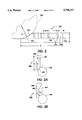
- FIG. 1 is a plan view of an electrical motor including the brush wear viewing feature of the present invention
- FIG. 1A is a plan view of a plug for the brush wear viewing feature of the present invention.
- FIG. 1B is a plan view of a label for the brush wear viewing feature of the present invention.
- FIG. 1C is a plan view of a transparent cover for the brush wear viewing feature of the present invention.
- FIG. 2 is an enlarged view of a brush of the FIG. 1 electrical motor
- FIG. 2A is an enlarged view of a brush of an alternate embodiment of the brush wear viewing feature of the present invention utilizing an axial stripe;
- FIG. 2B is an enlarged view of a brush an alternate embodiment of the brush wear viewing feature of the present invention utilizing a diagonal strip;
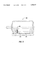
- FIG. 3 is a plan view of an alternate embodiment of an electrical motor including the brush wear viewing feature of the present invention.
- FIG. 4 is a schematic elevational view of an electrophotographic printing machine incorporating the FIG. 1 motor therein.
- FIG. 4 schematically depicts the various components of an electrophotographic printing machine incorporating the brush wear viewing feature of the present invention therein.
- the brush wear viewing feature of the present invention is particularly well adapted for use in the illustrative printing machine, it will become evident that the brush wear viewing feature is equally well suited for use in a wide variety of printing machines and are not necessarily limited in its application to the particular embodiment shown herein.
- the electrophotographic printing machine shown employs a photoconductive drum 16, although photoreceptors in the form of a belt are also known, and may be substituted therefor.
- the drum 16 has a photoconductive surface deposited on a conductive substrate.
- Drum 16 moves in the direction of arrow 18 to advance successive portions thereof sequentially through the various processing stations disposed about the path of movement thereof.
- Motor 20 rotates drum 16 to advance drum 16 in the direction of arrow 18.
- Drum 16 is coupled to motor 20 by suitable means such as a drive.
- a corona generating device indicated generally by the reference numeral 30, charges the drum 16 to a selectively high uniform electrical potential, preferably negative. Any suitable control, well known in the art, may be employed for controlling the corona generating device 30.
- a document to be reproduced is placed on a platen 22, located at imaging station B, where it is illuminated in known manner by a light source such as a tungsten halogen lamp 24.
- the document thus exposed is imaged onto the drum 16 by a system of mirrors 20, as shown.
- the optical image selectively discharges the surface 28 of the drum 16 in an image configuration whereby an electrostatic latent image 32 of the original document is recorded on the drum 16 at the imaging station B.
- a magnetic development system or unit indicated generally by the reference numeral 36 advances developer materials into contact with the electrostatic latent images.
- the magnetic developer unit includes a magnetic developer roller mounted in a housing.
- developer unit 36 contains a magnetic roller 40.
- the roller 40 advances toner particles into contact with the latent image.
- Appropriate developer biasing is may be accomplished via power supply 42, electrically connected to developer unit 36.
- the developer unit 36 develops the charged image areas of the photoconductive surface.
- This developer unit contains magnetic black toner, for example, particles 44 which are charged by the electrostatic field existing between the photoconductive surface and the electrically biased developer roll in the developer unit.
- Power supply 42 electrically biases the magnetic roll 40.
- a sheet of support material 58 is moved into contact with the toner image at transfer station D.
- the sheet of support material is advanced to transfer station D by a suitable sheet feeding apparatus, not shown.
- the sheet feeding apparatus includes a feed roll contacting the uppermost sheet of a stack copy sheets. Feed rolls rotate so as to advance the uppermost sheet from the stack into a chute which directs the advancing sheet of support material into contact with the photoconductive surface of drum 16 in a timed sequence so that the toner powder image developed thereon contacts the advancing sheet of support material at transfer station D.
- Transfer station D includes a corona generating device 60 which sprays ions of a suitable polarity onto the backside of sheet 58. This attracts the toner powder image from the drum 16 to sheet 58. After transfer, the sheet continues to move, in the direction of arrow 62, onto a conveyor (not shown) which advances the sheet to fusing station E.
- Fusing station E includes a fuser assembly, indicated generally by the reference numeral 64, which permanently affixes the transferred powder image to sheet 58.
- fuser assembly 64 comprises a heated fuser roller 66 and a pressure roller 68.
- Sheet 58 passes between fuser roller 66 and pressure roller 68 with the toner powder image contacting fuser roller 66. In this manner, the toner powder image is permanently affixed to sheet 58.
- a chute guides the advancing sheet 58 to a catch tray, also not shown, for subsequent removal from the printing machine by the operator. It will also be understood that other post-fusing operations can be included, for example, stapling, binding, inverting and returning the sheet for duplexing and the like.
- the residual toner particles carried by image and the non-image areas on the photoconductive surface are charged to a suitable polarity and level by a preclean charging device (not shown) to enable removal therefrom. These particles are removed at cleaning station F.
- the vacuum assisted, electrostatic, brush cleaner unit 70 is disposed at the cleaner station F.
- the cleaner unit has two brush rolls that rotate at relatively high speeds which creates mechanical forces that tend to sweep the residual toner particles into an air stream (provided by a vacuum source), and then into a waste container.
- a discharge lamp or corona generating device (not shown) dissipates any residual electrostatic charge remaining prior to the charging thereof for the next successive imaging cycle.
- a motor 20 employing the brush wear viewing feature 82 of the subject invention is shown.
- the motor 20 is enclosed, preventing the viewing of the brush 110 without the use of the brush wear viewing feature 82.
- the present invention may be practiced on any electrical motor 20 having a brush or brushes that transfer electricity from a fixed component or stator to a rotating component or armature.
- the motor 20 may be a standard, commercially available electrical motor with at least one brush and may, for example, be a DC (direct current) brush motor.
- the motor 20 may have suitable mounting arrangement such as face mounting, or may, as shown in FIG. 1, include a base 84 on which housing 86 is supported.
- the housing 86 includes a generally, cylindrically shaped peripheral portion 90 to which first end portion 92 and second end portion 94 are attached.
- the peripheral portion 90 is also secured to base 84.
- the motor could also be mounted by other means such as by end caps.
- the peripheral portion, first end portion 92, and second end portion 94 are made of any suitable durable material, for example, stamped steel.
- the base 84 is made of any suitable durable material, for example, cast iron or stamped steel.
- the peripheral portion 90 is secured to the base 84 by any suitable method, for example, by fasteners or by welding.
- the first end portion 92 is secured to the peripheral portion 90 by any suitable method, for example, by fasteners or by welding.
- the second end portion 94 is secured to the peripheral portion by any suitable method, for example, by fasteners or by welding.
- at least the first end portions 92 or the second end portion 94 are removably secured to the peripheral portion in order that the internal workings of the motor 20 may be installed and disassembled for service.
- shaft 100 Centrally located within the motor 20 and concentric with longitudinal axis 96 is shaft 100. Shaft 100 extends beyond at least second end portion 94. Further mechanical components are attached to shaft 100, for example, pulleys or gears (not shown).
- the shaft 100 is secured to the motor 20 by bearings 102 mounted in the first end portion 92 and the second end portion 94.
- An armature 104 is secured to shaft 100 and rotates therewith.
- Stator windings 106 are secured to the peripheral portion 90 of the motor 20 and remain stationary with the cylindrically shaped peripheral portion 90 of the motor 20.
- At least one brush 110 is used to interconnect the stator winding 106 with the armature 104.
- the motor 20 includes more than one brush 110.
- the brush 110 may be made of any suitable, durable electrically conductive material. For small to medium size brush type DC motors, conductive carbon brushes have been found to be satisfactory.
- the brush wear viewing feature 82 is in the form of an aperture 82 formed in first end portion 92 of the motor 20.
- the aperture 82 forms a viewing window for the brush 110.
- the aperture 82 may be located anywhere about either the first end portion 92, the second end portion 94, or the peripheral portion 90 of the motor 20.
- the aperture 82 is positioned as close as possible to the brush 110 and is so located that the brush 110 may be viewed when looking at an attitude normal to the surface of the motor 20.
- the aperture 82 is formed from first end portion 92.
- the brush 110 may thus be viewed through aperture 82 when viewing in the direction parallel to axis 96.
- the aperture 82 may have any suitable size and shape necessary to view the brush 110, but preferably has a shape similar to that of the brush 110, for example, an elongated slot as shown in FIG. 1.
- the aperture 82 is protected by a removable cover 112, in the form of a plug as shown in FIG. 1A.
- the plug 112 has a shape conformable to the aperture 82 and is made of a conformable material, e.g., a synthetic rubber.
- the cover may be in the form of label 112a as shown in FIG. 1B.
- the label 112a may include an adhesive back for securing the label 112a to the peripheral portion 90 of the motor 20.
- the cover may also be in the form of a transparent cover 112b as shown in FIG. 1C.
- the transparent cover 112b may include a transparent central portion 115b as well as an attaching area 113b for attaching the cover 112b to the peripheral portion 90 of the motor 20 the attaching area 113b may be in the form of label or a plug or include tabs or detents (not shown).
- the condition of the brush 110 may be observed through aperture 82 by removing the cover 112 or the label 112a. After inspection, the cover 112 or the label 112a may be reinstalled into the aperture 82 to prevent contamination from entering the motor 20.
- the brush 110 is shown in greater detail in FIG. 2.
- the brush 110 may have any suitable durable shape, but preferably has a rectangular configuration.
- the brush 110 includes contact zone 114 which is in contact with the armature 104 (see FIG. 1).
- the wearing of the brush 110 against the armature causes contact zone 114 to be described by radius R roughly equal to the radius of the armature.
- the brush 110 when in the form of a somewhat unpliable form, for example, when in the form of a carbon brush, is urged toward armature 104 by an loading means, for example a leaf or coil spring 105, loading the brush 110 toward the armature.
- an loading means for example a leaf or coil spring 105
- the brush includes visual indicators 120.
- the visual indicators 120 may be in any suitable form, for example, protrusions, notches, voids, or any other suitable visual feature on the brush 110.
- the visual indicators are in the form of marks.
- the invention may be practiced with a single mark positioned at the location of minimum brush length to permit the reuse of the motor in a rebuilt machine or may include a multitude of marks 120, as shown in FIG. 2, whereby the marks may indicate various conditions of the motor from an almost like new condition to a marginally operating position.
- the marks 120 may be applied to the brush in any suitable manner, for example, by etching or engraving the marks onto the brush.
- the marks 120 are preferably positioned somewhat tangential to the contact zone 114 or the wearing surface of the brush 110.
- the marks 120 are positioned perpendicular to longitudinal axis 122 of the brush 110.
- the marks 120 may extend any particular length as long as the length is long enough to be visually observable through the viewing window. For example, for a brush having a length A of approximately 0.50" and a thickness B of approximately 0.10", the marks have a length L of approximately 0.06" and a width W of approximately 0.25".
- the marks are preferably parallel to each other and spaced apart a distance D of approximately 0.07".
- the marks 120 are formed by applying a coating 124 to at least a portion of the brush 110 which will be worn by the armature 104.
- a coating 124 of, for example, white paint is particularly important when using a carbon brush which is typically black.
- the marks 120 are formed over the white coating 124 leaving the marks 120, the color of the brush 110 which is typically black.
- Each of the marks 120 represent the position when contacting the armature represent a certain remaining life on the motor.
- third mark from the left 126 may represent the minimum brush length to provide for a motor life suitable for a rebuilt machine.
- Brush 310 is similar in size and shape and materials as brush 110.
- Brush 310 includes an axial stripe 320 made of a coating, for example white paint.
- the stripe 320 extends for a length L3 from the contract zone 330 of the brush 310 to a point spaced from opposed end 340 of the brush 310.
- Length L3 is less than the entire length L4 of the brush 310.
- the distance L4-L3 represents the minimum allowable length of the brush 310 for an acceptable reusable motor brush 310.
- Brush 410 is similar in size and shape and materials as brush 110.
- Brush 410 includes an diagonal strip 420 made of a coating, for example white paint.
- the strip 420 extends diagonally across a face 430 of the brush 410.
- Distance D2 from the commutator 104 to the edge 440 between the strip 420 and the remainder of face 430 is an indication of remaining life of the brush 410.
- D2 may need to be at least 0.10 inches.
- Motor 226 is shown. Motor 226 is similar to motor 20, except that viewing feature 282 in the form of viewing window 282 is positioned on peripheral portion 290 of the motor 226. Brush 210 is urged upwardly by spring 205. Viewing of brush 210 is accomplished through the viewing window 282 in the peripheral portion 290.
- a motor By providing an electrical motor with a viewing window through which the condition of the brush may be viewed, a motor may be inspected while assembled and the remaining life of the motor can be determined. The remaining life determined from the condition of the brush will permit the reuse of motors in good condition and with sufficient remaining life without disassembling the motors and thus save labor and expense.
- a xerographic copy machine may be remanufactured utilizing existing motors without the requirement of replacing the motors or rebuilding the motors.
- the motor When a xerographic copy machine is returned from service to be remanufactured, the motor may be removed from the existing used machine. The plug is then removed from the viewing window and the inspector at the remanufacturing site views through the viewing window the condition of the brush. The number of marks remaining on the brush are then counted by the inspector and compared to a remanufacturing specification as to whether a sufficient quantity of the marks remain. For example, if three marks are required on the machine and say, for example, four are remaining, the motor may be reassembled into a remanufactured machine without the motor being disassembled and rebuilt or scrapped and replaced with a new motor.
Landscapes
- Engineering & Computer Science (AREA)
- Power Engineering (AREA)
- Motor Or Generator Current Collectors (AREA)
- Motor Or Generator Frames (AREA)
Abstract
Description
Claims (30)
Priority Applications (4)
| Application Number | Priority Date | Filing Date | Title |
|---|---|---|---|
| US08/620,818 US5708317A (en) | 1996-03-25 | 1996-03-25 | DC motor designed for asset recovery |
| JP9062631A JPH1014177A (en) | 1996-03-25 | 1997-03-17 | Motor |
| DE69702225T DE69702225T2 (en) | 1996-03-25 | 1997-03-20 | An electric motor |
| EP97301900A EP0798821B1 (en) | 1996-03-25 | 1997-03-20 | An electric motor |
Applications Claiming Priority (1)
| Application Number | Priority Date | Filing Date | Title |
|---|---|---|---|
| US08/620,818 US5708317A (en) | 1996-03-25 | 1996-03-25 | DC motor designed for asset recovery |
Publications (1)
| Publication Number | Publication Date |
|---|---|
| US5708317A true US5708317A (en) | 1998-01-13 |
Family
ID=24487523
Family Applications (1)
| Application Number | Title | Priority Date | Filing Date |
|---|---|---|---|
| US08/620,818 Expired - Lifetime US5708317A (en) | 1996-03-25 | 1996-03-25 | DC motor designed for asset recovery |
Country Status (4)
| Country | Link |
|---|---|
| US (1) | US5708317A (en) |
| EP (1) | EP0798821B1 (en) |
| JP (1) | JPH1014177A (en) |
| DE (1) | DE69702225T2 (en) |
Cited By (2)
| Publication number | Priority date | Publication date | Assignee | Title |
|---|---|---|---|---|
| US7936105B2 (en) | 2009-03-30 | 2011-05-03 | Denso International America, Inc. | Audible brush wear indicator for rotating electric machines |
| US20130244451A1 (en) * | 2012-03-14 | 2013-09-19 | Cutsforth Products, Inc. | Brush holder marking system and associated maintenance |
Families Citing this family (4)
| Publication number | Priority date | Publication date | Assignee | Title |
|---|---|---|---|---|
| CN1104992C (en) * | 1997-03-27 | 2003-04-09 | 三菱铝株式会社 | Brazing aluminum alloy powder composition and brazing method using such powder composition |
| DE10026176A1 (en) * | 2000-05-26 | 2002-01-10 | Schleifring Und Appbau Gmbh | Holding and contacting device for sliding contacts; PCB brush block |
| KR100991305B1 (en) * | 2002-04-19 | 2010-11-01 | 마크스 가부시기가이샤 | Electric stapler |
| DE10257623B4 (en) * | 2002-12-09 | 2008-07-24 | Schleifring Und Apparatebau Gmbh | Device for determining the length of brushes in grinding path arrangements or collectors |
Citations (16)
| Publication number | Priority date | Publication date | Assignee | Title |
|---|---|---|---|---|
| US1920659A (en) * | 1932-06-29 | 1933-08-01 | Elton T Naylon | Device for indicating wear of brushes |
| US2840732A (en) * | 1956-09-04 | 1958-06-24 | Gen Electric | Brush holder clamping arrangement |
| US3484939A (en) * | 1967-04-26 | 1969-12-23 | Gillette Co | Blade length indicator |
| US3609429A (en) * | 1970-02-02 | 1971-09-28 | Harris A Thompson | Brush wear indicator |
| US3922999A (en) * | 1973-11-02 | 1975-12-02 | Charles E Meginnis | Sight glass with wear indicating device |
| DE2538922A1 (en) * | 1975-09-02 | 1977-03-03 | Metabowerke Kg | Electric motor brush wear visual indicator - is flexible ribbon with indicator surface drawn past sight glass as brush wears |
| DE3031915A1 (en) * | 1980-08-23 | 1982-04-08 | Robert Bosch Gmbh, 7000 Stuttgart | Wear detecting appts. - senses wear of carbon brushes in motor by using contacts or by visual inspection |
| US4333095A (en) * | 1980-02-19 | 1982-06-01 | Reliance Electric Company | Brush wear indicator |
| US4338538A (en) * | 1980-04-18 | 1982-07-06 | Eltra Corporation | Removable brush holder for dynamoelectric machine |
| US4390870A (en) * | 1981-06-15 | 1983-06-28 | General Electric Company | Interface circuit for brush wear indicator application |
| US4528557A (en) * | 1982-04-23 | 1985-07-09 | Helwig Carbon, Inc. | Brush wear indicator |
| JPS6192135A (en) * | 1984-10-08 | 1986-05-10 | Matsushita Electric Ind Co Ltd | Usage time display device |
| US4636778A (en) * | 1983-10-03 | 1987-01-13 | Reliance Electric Company | Brush wear monitor |
| US4918348A (en) * | 1988-12-14 | 1990-04-17 | Prestolite Electric Incorporated | Brush wear indicator |
| US4989537A (en) * | 1989-08-01 | 1991-02-05 | Hutchinson Sr Jerry W | Wear indicator for vehicle air brakes |
| JPH06141504A (en) * | 1992-10-26 | 1994-05-20 | Fuji Electric Co Ltd | Fan shield inspection hole cover for measuring gap of rotating machine |
Family Cites Families (1)
| Publication number | Priority date | Publication date | Assignee | Title |
|---|---|---|---|---|
| US2089678A (en) * | 1935-06-15 | 1937-08-10 | Siemens Ag | Position indicator for carbon brushes |
-
1996
- 1996-03-25 US US08/620,818 patent/US5708317A/en not_active Expired - Lifetime
-
1997
- 1997-03-17 JP JP9062631A patent/JPH1014177A/en active Pending
- 1997-03-20 EP EP97301900A patent/EP0798821B1/en not_active Expired - Lifetime
- 1997-03-20 DE DE69702225T patent/DE69702225T2/en not_active Expired - Lifetime
Patent Citations (16)
| Publication number | Priority date | Publication date | Assignee | Title |
|---|---|---|---|---|
| US1920659A (en) * | 1932-06-29 | 1933-08-01 | Elton T Naylon | Device for indicating wear of brushes |
| US2840732A (en) * | 1956-09-04 | 1958-06-24 | Gen Electric | Brush holder clamping arrangement |
| US3484939A (en) * | 1967-04-26 | 1969-12-23 | Gillette Co | Blade length indicator |
| US3609429A (en) * | 1970-02-02 | 1971-09-28 | Harris A Thompson | Brush wear indicator |
| US3922999A (en) * | 1973-11-02 | 1975-12-02 | Charles E Meginnis | Sight glass with wear indicating device |
| DE2538922A1 (en) * | 1975-09-02 | 1977-03-03 | Metabowerke Kg | Electric motor brush wear visual indicator - is flexible ribbon with indicator surface drawn past sight glass as brush wears |
| US4333095A (en) * | 1980-02-19 | 1982-06-01 | Reliance Electric Company | Brush wear indicator |
| US4338538A (en) * | 1980-04-18 | 1982-07-06 | Eltra Corporation | Removable brush holder for dynamoelectric machine |
| DE3031915A1 (en) * | 1980-08-23 | 1982-04-08 | Robert Bosch Gmbh, 7000 Stuttgart | Wear detecting appts. - senses wear of carbon brushes in motor by using contacts or by visual inspection |
| US4390870A (en) * | 1981-06-15 | 1983-06-28 | General Electric Company | Interface circuit for brush wear indicator application |
| US4528557A (en) * | 1982-04-23 | 1985-07-09 | Helwig Carbon, Inc. | Brush wear indicator |
| US4636778A (en) * | 1983-10-03 | 1987-01-13 | Reliance Electric Company | Brush wear monitor |
| JPS6192135A (en) * | 1984-10-08 | 1986-05-10 | Matsushita Electric Ind Co Ltd | Usage time display device |
| US4918348A (en) * | 1988-12-14 | 1990-04-17 | Prestolite Electric Incorporated | Brush wear indicator |
| US4989537A (en) * | 1989-08-01 | 1991-02-05 | Hutchinson Sr Jerry W | Wear indicator for vehicle air brakes |
| JPH06141504A (en) * | 1992-10-26 | 1994-05-20 | Fuji Electric Co Ltd | Fan shield inspection hole cover for measuring gap of rotating machine |
Cited By (5)
| Publication number | Priority date | Publication date | Assignee | Title |
|---|---|---|---|---|
| US7936105B2 (en) | 2009-03-30 | 2011-05-03 | Denso International America, Inc. | Audible brush wear indicator for rotating electric machines |
| US20130244451A1 (en) * | 2012-03-14 | 2013-09-19 | Cutsforth Products, Inc. | Brush holder marking system and associated maintenance |
| US9099827B2 (en) * | 2012-03-14 | 2015-08-04 | Cutsforth, Inc. | Brush holder marking system and associated maintenance |
| US9874492B2 (en) | 2012-03-14 | 2018-01-23 | Cutsforth, Inc. | Brush holder marking system and associated maintenance |
| US10718688B2 (en) | 2012-03-14 | 2020-07-21 | Cutsforth, Inc. | Brush holder marking system and associated maintenance |
Also Published As
| Publication number | Publication date |
|---|---|
| EP0798821A1 (en) | 1997-10-01 |
| EP0798821B1 (en) | 2000-06-07 |
| DE69702225T2 (en) | 2000-10-26 |
| DE69702225D1 (en) | 2000-07-13 |
| JPH1014177A (en) | 1998-01-16 |
Similar Documents
| Publication | Publication Date | Title |
|---|---|---|
| US4984019A (en) | Electrode wire cleaning | |
| EP2413201B1 (en) | Processing box | |
| GB2097332A (en) | Monitoring useful life detachable machine units | |
| US6029019A (en) | Electrophotographic image recording apparatus with detection of proper installation of photosensitive drum | |
| US5905932A (en) | Method and apparatus for the removal of toner and magnetic carrier particles from a surface | |
| EP0026677B1 (en) | Magnetic photoreceptor cleaning system | |
| US5708317A (en) | DC motor designed for asset recovery | |
| US5134442A (en) | Electrode wire contamination prevention and detection | |
| US6223010B1 (en) | Resin product, method of disassembling the resin product, process cartridge, method of disassembling the process cartridge, and electrophotographic image forming apparatus | |
| US6289188B1 (en) | Non-leaking and easily remanufactured toner cartridge | |
| WO2012005900A1 (en) | Cleaning brush for electrostatographic apparatus | |
| JP2979851B2 (en) | Image forming device | |
| US6269236B1 (en) | Cleaning device for a photosensitive element | |
| US3650616A (en) | Mispuff detector | |
| JPH0141986B2 (en) | ||
| EP0620508B1 (en) | Cleaning apparatus | |
| US5715512A (en) | Apparatus and method for removing residual developer remaining on a photosensitive element | |
| US5196889A (en) | Apparatus for applying an electrical bias to a shell of a magnetic brush | |
| US20060088325A1 (en) | Image forming apparatus | |
| US20030044206A1 (en) | Performance sensing cleaning device | |
| EP0533176A2 (en) | Electrophotographic printing machine | |
| JP4801946B2 (en) | Life estimation method | |
| JP2002323786A (en) | Toner and image forming apparatus | |
| JPH01319761A (en) | Electrophotographic recorder | |
| US5839017A (en) | Developer level detection system |
Legal Events
| Date | Code | Title | Description |
|---|---|---|---|
| AS | Assignment |
Owner name: XEROX CORPORATION, CONNECTICUT Free format text: ASSIGNMENT OF ASSIGNORS INTEREST;ASSIGNORS:SIEGEL, ROBERT P.;WALTER, BUJALSKI;REEL/FRAME:007923/0407 Effective date: 19960319 |
|
| STCF | Information on status: patent grant |
Free format text: PATENTED CASE |
|
| FPAY | Fee payment |
Year of fee payment: 4 |
|
| AS | Assignment |
Owner name: BANK ONE, NA, AS ADMINISTRATIVE AGENT, ILLINOIS Free format text: SECURITY INTEREST;ASSIGNOR:XEROX CORPORATION;REEL/FRAME:013153/0001 Effective date: 20020621 |
|
| AS | Assignment |
Owner name: JPMORGAN CHASE BANK, AS COLLATERAL AGENT, TEXAS Free format text: SECURITY AGREEMENT;ASSIGNOR:XEROX CORPORATION;REEL/FRAME:015134/0476 Effective date: 20030625 Owner name: JPMORGAN CHASE BANK, AS COLLATERAL AGENT,TEXAS Free format text: SECURITY AGREEMENT;ASSIGNOR:XEROX CORPORATION;REEL/FRAME:015134/0476 Effective date: 20030625 |
|
| FPAY | Fee payment |
Year of fee payment: 8 |
|
| AS | Assignment |
Owner name: XEROX CORPORATION, NEW YORK Free format text: RELEASE BY SECURED PARTY;ASSIGNOR:JP MORGAN CHASE BANK, NA;REEL/FRAME:020031/0840 Effective date: 20061204 |
|
| AS | Assignment |
Owner name: XEROX CORPORATION, NEW YORK Free format text: RELEASE BY SECURED PARTY;ASSIGNOR:BANK ONE, NA;REEL/FRAME:020045/0582 Effective date: 20030625 |
|
| FPAY | Fee payment |
Year of fee payment: 12 |
|
| AS | Assignment |
Owner name: XEROX CORPORATION, CONNECTICUT Free format text: RELEASE BY SECURED PARTY;ASSIGNOR:JPMORGAN CHASE BANK, N.A. AS SUCCESSOR-IN-INTEREST ADMINISTRATIVE AGENT AND COLLATERAL AGENT TO JPMORGAN CHASE BANK;REEL/FRAME:066728/0193 Effective date: 20220822 |