US5703726A - Reverse telephoto lens - Google Patents
Reverse telephoto lens Download PDFInfo
- Publication number
- US5703726A US5703726A US08/631,500 US63150096A US5703726A US 5703726 A US5703726 A US 5703726A US 63150096 A US63150096 A US 63150096A US 5703726 A US5703726 A US 5703726A
- Authority
- US
- United States
- Prior art keywords
- lens
- focal length
- positive
- negative
- efl
- Prior art date
- Legal status (The legal status is an assumption and is not a legal conclusion. Google has not performed a legal analysis and makes no representation as to the accuracy of the status listed.)
- Expired - Lifetime
Links
- 230000005499 meniscus Effects 0.000 claims abstract description 38
- 239000006059 cover glass Substances 0.000 claims description 37
- 238000005452 bending Methods 0.000 claims description 6
- 238000000926 separation method Methods 0.000 abstract 1
- 230000004075 alteration Effects 0.000 description 37
- 201000009310 astigmatism Diseases 0.000 description 28
- 239000011521 glass Substances 0.000 description 14
- 238000004519 manufacturing process Methods 0.000 description 7
- 238000000465 moulding Methods 0.000 description 7
- 230000000694 effects Effects 0.000 description 6
- 230000011514 reflex Effects 0.000 description 6
- 206010010071 Coma Diseases 0.000 description 5
- 238000005516 engineering process Methods 0.000 description 4
- 238000005286 illumination Methods 0.000 description 4
- 206010073261 Ovarian theca cell tumour Diseases 0.000 description 3
- 238000000034 method Methods 0.000 description 3
- 208000001644 thecoma Diseases 0.000 description 3
- 238000012937 correction Methods 0.000 description 2
- 239000000463 material Substances 0.000 description 2
- 238000004891 communication Methods 0.000 description 1
- 150000001875 compounds Chemical class 0.000 description 1
- 238000010276 construction Methods 0.000 description 1
- 238000003384 imaging method Methods 0.000 description 1
- 238000010137 moulding (plastic) Methods 0.000 description 1
- 238000007639 printing Methods 0.000 description 1
- 239000010453 quartz Substances 0.000 description 1
- 238000001454 recorded image Methods 0.000 description 1
- VYPSYNLAJGMNEJ-UHFFFAOYSA-N silicon dioxide Inorganic materials O=[Si]=O VYPSYNLAJGMNEJ-UHFFFAOYSA-N 0.000 description 1
- 238000001228 spectrum Methods 0.000 description 1
Images

Classifications
-
- G—PHYSICS
- G02—OPTICS
- G02B—OPTICAL ELEMENTS, SYSTEMS OR APPARATUS
- G02B13/00—Optical objectives specially designed for the purposes specified below
- G02B13/04—Reversed telephoto objectives
Definitions
- This invention relates to reverse telephoto lenses.
- the invention can be used in any application in which a reverse telephoto lens is applicable, it is particularly designed to use in electronic camera systems, particularly electronic camera systems incorporating array photodetectors and birefringent blur filters. These electronic cameras produce digital images that are passed on to a computer in digital form over a digital communication link.
- Reverse telephoto lenses have found widespread use in single lens reflex cameras where they are commonly employed for short focal length lenses. Reverse telephoto designs are useful in these cameras because their long back focal length (back focus) provides clearance for a mirror located between the lens and the film plane. Such reverse telephoto single lens reflex camera lenses have a ratio of the back focal length over the effective focal length between 1.00 and 1.5, typically 1.15.
- the ratio of the vertex to vertex lens length over the effective focal length typically falls between 0.9 and 1.5.
- a reverse telephoto lens having lens elements arranged from a front, object side to a rear image side.
- a front negative group includes a front negative component and a rear positive component separated by a first airspace.
- a rear positive group is separated from the front negative group by a second airspace.
- a stop is located in the second airspace.
- the distance between the front negative component and the rear positive group is at least 2.5 times the focal length of the lens. According to preferred embodiments, this latter distance is greater than four times the focal length of the lens.
- the first airspace is between one and two times the focal length of the lens an the second airspace is between 1.5 and three times the focal length of the lens.
- the rear positive component of the front group is a single meniscus element which is concave to the object and the front negative component is a single meniscus element, convex to the object, providing a thick negative biconvex airspace between them.
- the preferred embodiments in addition to being of generally high quality and suitable for many uses, are particularly suitable for use with electronic cameras which produce digital images as output, particularly electronic cameras incorporating birefringent blur filters and array photodetectors in their design.
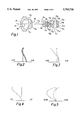
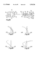
- FIG. 1 is a cross section of Example 1 of the invention.
- FIGS. 2, 3, 4, and 5 are graphical illustrations of longitudinal spherical aberration, astigmatism, distortion, and lateral color, respectively, of Example 1.
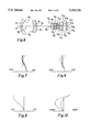
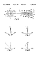
- FIGS. 6 through 10 are a cross section and graphical illustrations of the aberrations of Example 2 of the invention.
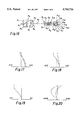
- FIGS. 11 through 15 are a cross section and graphical illustrations of the aberrations of Example 3 of the invention.
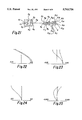
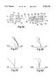
- FIGS. 16 through 20 are a cross section and graphical illustrations of the aberrations of Example 4 of the invention.
- FIGS. 21 through 25 are a cross section and graphical illustrations of the aberrations of Example 5 of the invention.
- FIGS. 26 through 30 are a cross section and graphical illustrations of the aberrations of Example 6 of the invention.
- FIGS. 31 through 35 are a cross section and graphical illustrations of the aberrations of Example 7 of the invention.
- FIGS. 36 through 40 are a cross section and graphical illustrations of the aberrations of Example 8 of the invention.
- the back focal length requirement for electronic camera lenses can be even more demanding than for 35 mm single lens reflex camera lenses with equivalent field coverage.
- Birefringent quartz blur filters are inserted between the rear vertex of the camera lens and the array photodetector to prevent luminance and color aliasing.
- the space requirements of the birefringent blur filter, a photodetector cover glass, and their associated mechanical mounting components require that the lens have a long back focal length.
- the distance between the array photodetector cover glass and the array photodetector itself must be large enough to prevent scratches and other imperfections on the cover glass from being sharply imaged on the array photodetector (or a very high quality cover obtained).
- a lens designed for use with an army photodetector having 640 ⁇ 480 pixels on 0.0074 mm centers prefers a back focal length of up to 7.5 mm to accommodate the birefringent blur filter, the photodetector cover glass, their associated mount components, and the air space between the cover glass and the array photodetector required to minimize the effects of cover glass imperfections on the recorded image.
- This lens typically has an effective focal length of 5.4 mm to achieve the same field coverage as a 40 mm lens used on a 35 mm film camera.
- the ratio of the back focal length over the effective focal length is 1.40 for the electronic camera lens and 1.15 for the 35 mm single lens reflex camera lens.
- the electronic camera has a more demanding back focal length requirement for equivalent field coverage.
- the back focal length requirement can be reduced to that necessary for the space requirements of the birefringent blur filter, the photodetector cover glass, and their associated mounting components.
- the 7.5 mm back focal length preference given in the previous example can be reduced to 6.3 mm.
- the ratio of back focal length over effective focal length can thereby be reduced to about 1.15, which is equivalent to the ratio for 35 mm format single lens reflex cameras. This is a feasible but less desirable solution because losing control of the quality of the cover glass can produce a high scrap rate for the array photodetector, which is generally among the most expensive components in the camera.
- Lenses for use in electronic cameras also require a higher relative illumination in the comer than lenses for fill cameras because the dynamic range of electronic photodetectors is smaller than photographic film. This requirement limits the amount of vignetting that can be tolerated and makes the design more demanding.
- Lenses for fill cameras typically meet a 25% to 30% relative illumination requirement at the maximum field angle. All the embodiments of the invention provide at least 45% relative illumination at the maximum field angle.
- the short focal length lenses used in electronic cameras require small lens elements. Manufacture of these lens elements using glass or plastic molding techniques can offer significant cost savings over conventional grind and polish techniques. However, using molding technology to manufacture the lens elements imposes restrictions on the glass choice used in the lens design. Several embodiments of the invention use glass choices which are compatible with current glass molding technology. In some cases, aspheric surfaces compatible with current glass molding technology are used to improve performance of the design.
- Lenses for use in electronic cameras have back focal length requirements that are similar to lenses used in video camcorders since both systems use array photodetectors and birefringent blur filters.
- Video camcorders lenses also have a large ratio of lens length over focal length because of their short focal lengths.
- Image quality of video camcorders is limited by recording standards for consumer video tape and broadcast television standards.
- Electronic cameras images are stored in digital form and are not limited by video tape recording standards.
- the digital images from electronic cameras are viewed on high-resolution computer displays that are not limited by broadcast television standards.
- Digital images from electronic cameras are also used to create near photographic quality prints using a variety of printing technologies. All embodiments of the invention have high image quality that is suitable for use with digital electronic photography systems.
- reverse telephoto lenses having relative apertures of f/2.8, semi-field angles of 29 to 32 degrees, back focal lengths between 1.10 and 1.60 times their effective focal length, and provide high relative illumination at the edge of their field of view.
- They are comprised of five elements and have the form (-+ stop +-+).
- the lenses are corrected for use with plane parallel plates, representing the birefringent blur filter and array photodetector cover glass, located between the last lens element and the image plane.
- the rear three elements can be moved with respect to the first two elements and the stop to focus.
- the first lens element is negative meniscus with its convex side toward the object.
- the second lens element is positive meniscus with its concave side toward the object providing a strong biconvex negative airspace to the front of the lens.
- the third and fifth element are positive biconvex.
- the fourth element is negative biconcave.
- Several embodiments of this form incorporate an aspheric surface in the rear group.
- C 1 and C 2 are the curvatures of the first and second radii of the element.
- the radii R and distances D are numbered from front (object side) to rear and are in millimeters.
- the indices N and Abbe numbers V are also numbered from front to rear. The indices are for the D line of the spectrum.
- the reverse telephoto lens satisfies the inequalities set out in the next few paragraphs:
- Equation (1) if the Abbe number is less than 45, the astigmatism in the resulting design is difficult to correct.
- An Abbe number of 55 is at the edge of the glass chart for the preferred index; a design using it for the first element can be adequately corrected.
- Equation (2) if the Abbe number is less than 30, the coma in the resulting design is difficult to correct. If it is allowed to exceed 55, the astigmatism in the resulting design is undesirably high.
- Equation (3) if the Abbe number is less than 44, more lateral color is induced into the design.
- An Abbe number of 55 is at the edge of the glass chart for the preferred index; a design using it for the third element can be adequately corrected.
- Equation (4) if the Abbe number exceeds 33, significant lateral color is induced into the design. An Abbe number of 28 is at the edge of the glass chart for this index; a design using it for the fourth element can be adequately corrected.
- Equation (5) if the Abbe number is less than 39, significant lateral color will be induced into the design. If it is allowed to exceed 65, the astigmatism in the resulting design is difficult to correct. ##EQU2## where efl n is the effective focal length of the nth element, and efl is the focal length of the lens.
- Equation (6) if the ratio is less than -3.20, the spherical aberration and lateral color in the resulting design is difficult to correct. If the ratio exceeds -2.41, the lateral color in the resulting design is difficult to correct. In Equation (7), if the ratio is less than 4.97, the lateral color and astigmatism in the resulting design are difficult to correct. If the ratio exceeds 9.80, the lateral color is difficult to correct. In Equation (8), if the ratio is less than 0.79, the coma and field curvature in the design is difficult to correct. If the ratio exceeds 1.23, the spherical aberration in the resulting design is difficult to correct.
- Equation (9) if the ratio is less than -0.82, the spherical aberration in the resulting design is difficult to correct. If the ratio exceeds -0.53, the field curvature in the resulting design is difficult to correct. In Equation (10), if the ratio is less than 1.0, the astigmatism in the resulting design is difficult to correct. If the ratio exceeds 1.50, the field curvature in the resulting design is difficult to correct.
- Maintaining Equation (11), helps correct the lateral color astigmatism, spherical aberration and astigmatism. Maintaining Equation (12), helps correct astigmatism. Maintaining Equation (13), helps correct the spherical aberration and coma. Maintaining Equation (14), maintains the field curvature and helps correct astigmatism. Maintaining Equation (15), helps correct the coma, field curvature, and astigmatism. Maintaining Equation (15) also helps maintain the field curvature. ##EQU3##
- D 2 is the air space between the first and second elements. Maintaining Equation (16) helps correct astigmatism, distortion and coma.
- D 4 is the air space between the second element and the stop. Maintaining Equation (17) helps correct coma, spherical aberration and astigmatism.
- D 5 is the air space between the stop and the third element. Maintaining Equation (18) helps correct astigmatism, spherical aberration and lateral color.
- the overall corrections can be improved with less vignetting if the distance between the front negative component and the rear positive group is at least 2.5 times the focal length of the lens and preferably is greater than four times the focal length of the lens.
- Example I of the invention is a reverse telephoto design having the form (-+ stop +-+), where the first element is meniscus with the convex side towards the object, the second element is meniscus with the concave side toward the object, the third element is biconvex, the fourth element is biconcave, and the fifth element is biconvex.
- the lens is corrected for use with a birefringent blur filter array photodetector cover glass located behind the lens.
- the ratio of the back focal length over the effective focal length is 1.19 and the ratio of the lens length over the effective focal length is 4.64.
- the f-number is f/2.84 and the lens covers a total field angle of 64°.
- the focal length is 6.84 mm and the lens is suitable for use with an array photodetector having a semi-diagonal of 4.15 mm.
- Example I satisfies Equations (1) through (18).
- FIG. 1 is a cross section of Example 1.
- FIGS. 2, 3, 4, and 5 are graphical illustrations of the various aberrations of Example 1.
- FIG. 2, 3, 4, and 5 show the longitudinal spherical aberration, astigmatism, distortion, and lateral color respectively.
- the primary wavelength is e
- the short wavelength is F
- the long wavelength is C.
- vignetting is controlled on the rear surface of the second element and the front surface of the fourth element.
- the clear apertures of these surfaces are restricted to 10.89 mm and 3.80 mm respectively.
- the image plane illuminance at the maximum field angle is 51% of the axial illuminance when vignetting and cos 4 fall-off are taken into account.
- the two plano-plano elements following the fifth lens element model the birefringent blur filter and array photodetector cover glass for the purposes of lens design.
- the blur filter is modeled here using a single isotropic material rather than a sandwich of birefringent materials.
- the performance of an imaging system comprising the lens and birefringent blur filter depends on the construction details of the birefringent blur filter. This can be computed using well-known methods.
- the aberration plots presented in FIG. 1 are computed using the numerical values given in the table below.
- the values of D11, D13, and D15 can be adjusted without affecting the performance of the design, provided their sum is held constant.
- the lens can be focused by moving the three elements behind the stop; D5 and D11 are adjusted such that their sum is constant.
- Example 2 of the invention is a reverse telephoto design having the form (-+ stop +-+), where the first element is meniscus with the convex side towards the object, the second element is meniscus with the concave side toward the object, the third element is biconvex, the fourth element is biconcave, and the fifth element is biconvex.
- the lens is corrected for use with a birefringent blur filter array photodetector cover glass located behind the lens.
- the ratio of the back focal length over the effective focal length is 1.19 and the ratio of the lens length over the effective focal length is 5.19.
- the f-number is f/2.84 and the lens covers a total field angle of 64°.
- the focal length is 6.83 mm and the lens is suitable for use with an array photodetector having a semi-diagonal of 4.15 mm.
- the elements in this design are optimized for fabrication by molding.
- Example 2 satisfies Equations (1) through (18).
- FIG. 6 is a cross section of Example 2 and FIGS. 7 through 10 are graphical illustrations of the various aberrations of Example II.
- vignetting is controlled on the front surface of the fourth element.
- the clear aperture of this surface is restricted to 3.64 mm.
- the image plane illuminance at the maximum field angle is 50% of the axial illuminance when vignetting and cos 4 fall-off are taken into account.
- the two plano-plano elements following the fifth lens element model the birefringent blur filter and array photodetector cover glass for the purposes of lens design.
- the aberration plots presented in FIGS. 5-10 are computed using the numerical values given in the table below.
- the values of D11, D13, and D15 can be adjusted without affecting the performance of the design, provided their sum is held constant.
- the lens can be focused by moving the three elements behind the stop; D5 and D11 are adjusted such that their sum is constant.
- Example 3 of the invention is a reverse telephoto design having the form (-+ stop +-+), where the first element is a biconcave len element, the second element is meniscus with the concave side toward the object, the third element is biconvex, the fourth element is biconcave, and the fifth element is biconvex.
- the third and fourth element form a cemented doublet.
- the lens is corrected for use with a birefringent blur filter and an array photodetector cover glass located behind the lens.
- the ratio of the back focal length over the effective focal length is 1.19 and the ratio of the lens length over the effective focal length is 5.07.
- the f-number is f/2.84 and the lens covers a total field angle of 64°.
- the focal length is 6.83 mm and the lens is suitable for use with an array photodetector having a semi-diagonal of 4.15 mm.
- Example 3 satisfies Equations (1) through (5).
- FIG. 11 is a cross section of Example 3 and FIGS. 12-15 are graphical illustrations of the various aberrations of Example 3.
- vignetting is controlled on the rear surface of the fifth element.
- the clear aperture of this surface is restricted to 4.30 mm.
- the image plane illuminance at the maximum field angle is 45% of the axial illuminance when vignetting and cos 4 fall-off are taken into account.
- the aberration plots presented in FIG. 3 are computed using the numerical values given in the table below.
- the values of D11, D13, and D15 can be adjusted without affecting the performance of the design, provided their sum is held constant.
- the lens can be focused by moving the three elements behind the stop; D5 and D11 are adjusted such that their sum is constant.
- Example 4 of the invention is a reverse telephoto design having the form (-+ stop +-+), where the first element is meniscus with the convex side towards the object, the second element is meniscus with the concave side toward the object, the third element is biconvex, the fourth element is biconcave, and the fifth element is biconvex.
- the rear surface of the third element is aspheric for improved performance.
- the lens is corrected for use with a birefringent blur filter and an array photodetector cover glass located behind the lens.
- the ratio of the back focal length over the effective focal length is 1.48 and the ratio of the lens length over the effective focal length is 7.53.
- the f-number is f/2.84 and lens covers a total field angle of 59°.
- the focal length is 5.36 mm and the lens is suitable for use with an array photodetector having a semi-diagonal of 2.96 mm.
- the lens satisfies the following conditions for the Abbe number of each element:
- Maintaining Equation (19) helps correct astigmatism, lateral color, and distortion.
- An Abbe number of 55 is at the edge of the glass chart for the preferred index; a design using it for the first element can be adequately corrected.
- Maintaining Equation (20) helps correct distortion and lateral color.
- Maintaining Equation (21) helps correct astigmatism, distortion, and lateral color.
- An Abbe number of 52 is at the edge of the glass chart for the preferred index; a design using it for the third element can be adequately corrected.
- an Abbe number of 25 is at the edge of the glass chart for this index; a design using it for the fourth element can be adequately corrected. If the Abbe number exceeds 35, too much lateral color is induced into Example 4. In Equation (23), if the Abbe number is less than 40, too much lateral color will be induced into Example 4. If it is allowed to exceed 65, the astigmatism in the resulting design are difficult to correct.
- the design satisfies the following conditions on the ratio of the focal length of each element over the focal length of the design: ##EQU4##
- Maintaining Equation (24) helps correct lateral color and field curvature. Maintaining Equation (25) helps correct lateral color and distortion. Maintaining Equation (26) helps correct distortion, coma and astigmatism. Maintaining Equation (27) helps correct distortion and astigmatism. Maintaining Equation (28) helps correct astigmatism.
- Maintaining Equation (29) helps correct lateral color, distortion and spherical aberration.
- Maintaining Equation (30) helps correct lateral color, field curvature, and astigmatism.
- Maintaining Equation (31) helps correct distortion and astigmatism.
- Maintaining Equation (32) helps correct spherical aberration and astigmatism.
- Maintaining Equation (33) helps correct distortion, coma and astigmatism.
- bendings in Equation (33) for the range -1.11 ⁇ X 5 ⁇ -1.00 describe a fifth element that is meniscus with its concave side toward the object rather than biconvex.
- Example 6 uses a meniscus fifth element.
- the design satisfies the following conditions on the ratios of three of the air spaces over the focal length of the design: ##EQU5##
- D 2 is the air space between the first and second elements. Maintaining Equation (34) helps correct spherical aberration, distortion and astigmatism. D 4 is the air space between the second element and the stop. Maintaining Equation (35) helps correct spherical aberration, field curvature, and distortion. D 5 is the air space between the stop and the third element. Maintaining Equation (36) helps correct distortion and astigmatism.
- the rear surface of the third element in Examples 4-7 is aspheric.
- the surface sag is described by: ##EQU6##
- Example 4 satisfies Equations (19) through (37).
- FIG. 16 is a cross section of Example 4 and FIGS. 17 through 20 are graphical illustrations of the various aberrations of Example 4.
- vignetting is controlled on the rear surface of the second element, the rear surface of the third element, and the rear surface of the fifth element.
- the clear aperture of these surfaces are restricted to 9.96 mm, 3.76 mm, and 5.20 mm, respectively.
- the image plane illuminance at the maximum field angle is 45% of the axial illuminance when vignetting and cos 4 fall-off are taken into account.
- the two plano-plano elements following the fifth lens element model the birefringent blur filter and array photodetector cover glass for the purposes of lens design.
- Decentering or tilting the aspheric surface in Example 4 has only a small effect on the performance of the design. This is an advantage because it allows relaxed manufacturing tolerances on fabricating, centering, and mounting the aspheric element.
- the table below shows the effect of 1 minute of tilt and 0.010 mm of decenter of the aspheric surface in Example 4 on the performance of the design. Performance is evaluated at 70% of maximum field.
- Linear & Angular field tilt are based on tangential field only.
- Decenter Values DCY 0.010000.
- Example 5 of the invention is a reverse telephoto design having the form (-+ stop +-+), where the first element is biconcave, the second element is meniscus with the concave side toward the object, the third element is biconvex, the fourth element is biconcave, and the fifth element is biconvex.
- the rear surface of the third element is aspheric.
- the lens is corrected for use with a birefringent blur filter and an array photodetector cover glass located behind the lens.
- the ratio of the back focal length over the effective focal length is 1.51 and the ratio of the lens length over the effective focal length is 7.21.
- the f-number is f/2.84 and lens covers a total field angle of 59.5°.
- the focal length is 5.36 mm and the lens is suitable for use with an array photodetector having a semi-diagonal of 2.96 mm.
- Example 5 satisfies Equations (19) through (37).
- FIG. 21 is a cross section of Example 5 and FIGS. 22 through 25 are graphical illustrations of the various aberrations of Example 5.
- vignetting is controlled on the rear surface of the second element, the rear surface of the third element, and the rear surface of the fifth element.
- the clear aperture of these surfaces are restricted to 9.96 mm, 3.76 mm, and 5.20 mm, respectively.
- the image plane illuminance at the maximum field angle is 45% of the axial illuminance when vignetting and cos 4 fall-off are taken into account.
- the aberration plots presented in FIG. 5 are computed using the numerical values given in the table below.
- D11, D13, and D15 can be adjusted without affecting the performance of the design, provided their sum is held constant.
- the long back focal length of this design allows the array photodetector cover glass to be displaced a sufficient distance from the photo sites to minimize the effect of cover glass imperfections on the image quality.
- the lens can be focused by moving the three elements behind the stop; D5 and D11 are adjusted such that their sum is constant. Elements 3, 4, and 5 are optimized for fabrication by glass molding.
- Example 6 of the invention is a reverse telephoto design having the form (-+ stop +-+), where the first element is meniscus with the convex side toward the object, the second element is meniscus with the concave side toward the object, the third element is biconvex, the fourth element is biconcave, and the fifth element is meniscus with the concave side toward the object.
- the rear surface of the third element is aspheric.
- the lens is corrected for use with a birefringent blur filter and an array photodetector cover glass located behind the lens.
- the ratio of the back focal length over the effective focal length is 1.49 and the ratio of the lens length over the effective focal length is 7.51.
- the f-number is f/2.84 and the lens covers a total field angle of 58.6°.
- the focal length is 5.37 mm and the lens is suitable for use with an array photodetector having a semi-diagonal of 2.96 mm.
- Example 6 satisfies Equations (19) through (37).
- FIG. 26 is a cross section of Example 6 and FIGS. 29 through 30 are graphical illustrations of the various aberrations of Example 4.
- vignetting is controlled on the rear surface of the second element, the rear surface of the third element, and the rear surface of the fifth element.
- the clear aperture of these surfaces are restricted to 10.66 mm, 3.55 mm, and 5.34 mm, respectively.
- the image plane illuminance at the maximum field angle is 45% of the axial illuminance when vignetting and cos 4 fall-off are taken into account.
- the aberration plots presented in FIG. 6 are computed using the numerical values given in the table below.
- D11, D13, and D15 can be adjusted without affecting the performance of the design, provided their sum is held constant.
- the long back focal length of this design allows the array photodetector cover glass to be displaced a sufficient distance from the photosites to minimize the effect of cover glass imperfections on the image quality.
- the lens can be focused by moving the three elements behind the stop; D5 and D11 are adjusted such that their sum is constant. Elements 3, 4, and 5 are optimized for fabrication by glass molding.
- Example 7 of the invention is a reverse telephoto design having the form (-+ stop +-+), where the first element is meniscus with the convex side toward the object, the second element is meniscus with the concave side toward the object, the third element is biconvex, the fourth element is biconcave, and the fifth element is biconvex.
- the rear surface of the third element is aspheric.
- the lens is corrected for use with a birefringent blur filter and an array photodetector cover glass located behind the lens.
- the ratio of the back focal length over the effective focal length is 1.16 and the ratio of the lens length over the effective focal length is 5.77.
- the f-number is f/2.84 and the lens covers a total field angle of 58.8°.
- the focal length is 5.40 mm and the lens is suitable for use with an array photodetector having a semi-diagonal of 2.96 mm.
- FIG. 31 is a cross section of Example 7 and FIGS. 32 through 35 are graphical illustrations of the various aberrations of Example 7.
- vignetting is controlled on the rear surface of the second element, the front surface of the third element, and the rear surface of the fifth element.
- the clear aperture of these surfaces are restricted to 8.64 mm, 4.04 mm, and 5.40 mm, respectively.
- the image plane illuminance at the maximum field angle is 49% of the axial illuminance when vignetting and cos 4 fall-off are taken into account.
- the two plano-plano elements following the fifth lens element model the birefringent blur filter and array photodetector cover glass for the purposes of lens design.
- D11, D13, and D15 are computed using the numerical values given in the table below.
- the values of D11, D13, and D15 can be adjusted without affecting the performance of the design, provided their sum is held constant.
- the lens can be focused by moving the three elements behind the stop; D5 and D11 are adjusted such that their sum is constant.
- Example 8 of the invention is a reverse telephoto design having the form (-+ stop +-+), where the first element is meniscus with the convex side toward the object, the second element is meniscus with the concave side toward the object, the third element is biconvex, the fourth element is biconcave, and the fifth element is biconvex.
- the lens is corrected for use with a birefringent blur filter and an array photodetector cover glass located behind the lens.
- the ratio of the back focal length over the effective focal length is 1.16 and the ratio of the lens length over the effective focal length is 4.86.
- the f-number is f/2.84 and the lens covers a total field angle of 60°.
- the focal length is 5.40 mm and the lens is suitable for use with an array photodetector having a semi-diagonal of 2.96 mm.
- FIG. 36 is a cross section of Example 7 and FIGS. 37 through 40 are graphical illustrations of the various aberrations of Example 8.
- vignetting is controlled on the rear surface of the second element, the rear surface of the third element, and the rear surface of the fourth element.
- the clear aperture of these surfaces are restricted to 6.70 mm, 3.62 mm, and 3.96 mm, respectively.
- the image plane illuminance at the maximum field angle is 46% of the axial illuminance when vignetting and cos 4 fall-off are taken into account.
- the two plano-plano elements following the fifth lens element model the birefringent blur filter and array photodetector cover glass for the purposes of lens design.
- D11, D13, and D15 are computed using the numerical values given in the table below.
- the values of D11, D13, and D15 can be adjusted without affecting the performance of the design, provided their sum is held constant.
- the lens can be focused by moving the three elements behind the stop; D5 and D11 are adjusted such that their sum is constant.
Landscapes
- Physics & Mathematics (AREA)
- General Physics & Mathematics (AREA)
- Optics & Photonics (AREA)
- Lenses (AREA)
Abstract
Description
45≦V.sub.1 ≦55 (1)
30≦V.sub.2 ≦55 (2)
44≦V.sub.3 ≦55 (3)
28≦V.sub.4 ≦33 (4)
39≦V.sub.5 ≦65 (5)
-3.05≦X.sub.1 ≦-2.17 (11)
-11.3≦X.sub.2 ≦-4.3 (12)
0.22≦X.sub.3 ≦0.74 (13)
-0.40≦X.sub.4 ≦0.19 (14)
-0.75≦X.sub.5 ≦0.00 (15)
              TABLE 1
______________________________________
                                  Back focal
efl = 6.84
         F number = 2.84
                      Full field = 64°
                                  length = 8.15
______________________________________
R1 = 13.43
         D1 = 1.75    N1 = 1.77250
                                  V1 = 49.6
R2 = 6.49
         D2 = 7.23
R3 = -12.19
         D3 = 3.68    N3 = 1.58215
                                  V3 = 42.1
R4 = -9.51
         D4 = 10.06
R5 = 0.00
         D5 = 1.75
R6 = 6.42
         D6 = 2.60    N6 = 1.77250
                                  V6 = 49.6
R7 = -10.05
         D7 = 0.60
R8 = -5.89
         D8 = 1.50    N8 = 1.72825
                                  V8 = 28.4
R9 = 5.89
         D9 = 0.70
R10 = 30.92
         D10 = 1.86   N10 = 1.65113
                                  V10 = 55.9
R11 = -6.56
         D11 = 1.05
R12 = 0.00
         D12 = 3.56   N12 = 1.54430
                                  V12 = 70.2
R13 = 0.00
         D13 = 3.00
R14 = 0.00
         D14 = 0.76   N14 = 1.53338
                                  V14 = 61.3
R15 = 0.00
         D15 = 1.32
______________________________________
              TABLE II
______________________________________
                                  Back focal
efl = 6.84
         F number = 2.84
                      Full field = 64°
                                  length = 8.15
______________________________________
R1 = 15.54
         D1 = 1.50    N1 = 1.72800
                                  V1 = 50.6
R2 = 6.83
         D2 = 10.29
R3 = -13.56
         D3 = 3.68    N3 = 1.72800
                                  V3 = 50.6
R4 = -10.18
         D4 = 11.09
R5 = 0.00
         D5 = 1.74
R6 = 5.75
         D6 = 2.60    N6 = 1.72800
                                  V6 = 50.6
R7 = -19.53
         D7 = 0.57
R8 = -8.50
         D8 = 1.50    N8 = 1.72595
                                  V8 = 28.3
R9 = 5.02
         D9 = 0.60
R10 = 16.14
         D10 = 1.86   N10 = 1.64673
                                  V10 = 55.5
R11 = -7.60
         D11 = 1.05
R12 = 0.00
         D12 = 3.56   N12 = 1.54430
                                  V12 = 70.2
R13 = 0.00
         D13 = 3.00
R14 = 0.00
         D14 = 0.76   N14 = 1.53338
                                  V14 = 61.3
R15 = 0.00
         D15 = 1.32
R16 = 0.00
         D16 = -0.05
______________________________________
              TABLE 3
______________________________________
                                  Back focal
efl = 6.83
         F number = 2.84
                      Full field = 64°
                                  length = 8.15
______________________________________
R1 = -329.68
         D1 = 1.50    N1 = 1.71300
                                  V1 = 53.8
R2 = 9.26
         D2 = 10.90
R3 = -116.45
         D3 = 3.68    N3 = 1.71300
                                  V3 = 53.8
R4 = -14.00
         D4 = 10.24
R5 = 0.00
         D5 = 1.75
R6 = 5.03
         D6 = 2.60    N6 = 1.69350
                                  V6 = 53.3
R7 = -4.23
         D7 = 1.52    N7 = 1.78179
                                  V7 = 37.1
R8 = 4.23
         D8 = 0.60
R9 = 16.98
         D9 = 1.86    N9 = 1.51680
                                  V9 = 64.2
R10 = -6.36
         D10 = 1.03
R11 = 0.00
         D11 = 3.56   N11 = 1.54430
                                  V11 = 70.2
R12 = 0.00
         D12 = 3.00
R13 = 0.00
         D13 = 0.76   N13 = 1.53338
                                  V13 = 61.3
R14 = 0.00
         D14 = 1.33
______________________________________
35≦V.sub.1 ≦55 (19)
36≦V.sub.2 ≦45 (20)
45≦V.sub.3 ≦52 (21)
25≦V.sub.4 ≦35 (22)
40≦V.sub.5 ≦65 (23)
-1.90≦X.sub.1 ≦-0.75 (29)
-23.8≦X.sub.2 ≦-3.9 (30)
-0.25≦X.sub.3 ≦0.54 (31)
-0.40≦X.sub.4 ≦0.33 (32)
-1.11≦X.sub.5 ≦-0.27 (33)
-27.00≦k≦6.40 (37)
              TABLE 4
______________________________________
                                  Back focal
efl = 5.36 F number = 2.84
                       Full field = 59°
                                  length = 7.99
______________________________________
R1 = 31.76 D1 = 5.00   N1 = 1.69100
                                  V1 = 54.7
R2 = 6.61  D2 = 5.65
R3 = -10.96
           D3 = 4.00   N3 = 1.62004
                                  V3 = 36.4
R4 = -8.99 D4 = 15.00
R5 = 0.00  D5 = 1.59
R6 = 6.91  D6 = 3.00   N6 = 1.72800
                                  V6 = 50.6
C7 = -0.087589
           D7 = 1.00
k7 = -3.447987
R8 = -6.33 D8 = 1.89   N8 = 1.78200
                                  V8 = 26.0
R9 = 6.33  D9 = 0.84
R10 = 24.51
           D10 = 2.35  N10 = 1.79980
                                  V10 = 46.2
R11 = -6.51
           D11 = 3.28
R12 = 0.00 D12 = 3.02  N12 = 1.54430
                                  V12 = 70.2
R13 = 0.00 D13 = 1.50
R14 = 0.00 D14 = 0.76  N14 = 1.53338
                                  V14 = 61.3
R15 = 0.00 D15 = 0.77
______________________________________
______________________________________
Linear Fld    Angular Fld          RMS Spot
Tilt          Tilt       RMS OPD   Dia
______________________________________
Nominal 0.00000   0.000      0.198966
                                     0.006567
values for
entire design
______________________________________
______________________________________
         Linear   Angular          RMS
Surface  Fld. Tilt
                  Fld. Tilt RMS OPD
                                   Spot Dia
______________________________________
7 TLA    -0.0018  -1.024    0.000168
                                   0.000011
DCY      -0.00641 -5.572    0.000754
                                   0.000046
______________________________________
              TABLE 5
______________________________________
                                  Back focal
efl = 5.36
          F number = 2.84
                      Full field = 59.5°
                                  length = 8.105
______________________________________
R1 = -100.00
          D1 = 5.00   N1 = 1.69100
                                  V1 = 54.7
R2 = 8.17 D2 = 3.99
R3 = -15.71
          D3 = 4.00   N3 = 1.62004
                                  V3 = 36.4
R4 = -9.41
          D4 = 15.00
R5 = 0.00 D5 = 1.59
R6 = 7.03 D6 = 3.00   N6 = 1.72800
                                  V6 = 50.6
c7 = -0.093853
          D7 = 1.00
k7 = -1.692032
R8 = -6.15
          D8 = 1.89   N8 = 1.78206
                                  V8 = 26.0
R9 = 6.15 D9 = 0.84
R10 = 27.13
          D10 = 2.35  N10 = 1.79980
                                  V10 = 46.2
R11 = -6.25
          D11 = 3.28
R12 = 0.00
          D12 = 3.02  N12 = 1.54430
                                  V12 = 70.2
R13 = 0.00
          D13 = 1.50
R14 = 0.00
          D14 = 0.76  N14 = 1.53338
                                  V14 = 61.3
R15 = 0.00
          D15 = 0.87
______________________________________
              TABLE 6
______________________________________
                                  Back focal
efl = 5.37
          F number = 2.84
                      Full field = 58.6°
                                  length = 8.01
______________________________________
R1 = 16.05
          D1 = 5.00   N1 = 1.69100
                                  V1 = 54.7
R2 = 5.80 D2 = 5.65
R3 = -8.20
          D3 = 4.00   N3 = 1.62004
                                  V3 = 36.4
R4 = -8.09
          D4 = 15.00
R5 = 0.00 D5 = 1.59
R6 = 8.09 D6 = 3.00   N6 = 1.72800
                                  V6 = 50.6
c7 = -0.106097
          D7 = 1.00
k7 = -6.680424
R8 = 6.82 D8 = 1.89   N8 = 1.78200
                                  V8 = 26.0
R9 = 6.82 D9 = 0.84
R10 = -96.45
          D10 = 2.35  N10 = 1.79980
                                  V10 = 46.2
R11 = -5.10
          D11 = 3.28
R12 = 0.00
          D12 = 3.02  N12 = 1.54430
                                  V12 = 70.2
R13 = 0.00
          D13 = 1.50
R14 = 0.00
          D14 = 0.76  N14 = 1.53338
                                  V14 = 61.3
R15 = 0.00
          D15 = 0.78
______________________________________
______________________________________
                                  Back focal
efl = 5.40
          F number = 2.84
                      Full field = 58.8°
                                  length = 6.29
______________________________________
R1 = 18.73
          D1 = 1.50   N1 = 1.51680
                                  V1 = 64.2
R2 = 5.29 D2 = 3.72
R3 = -8.77
          D3 = 4.00   N3 = 1.69680
                                  V3 = 55.5
R4 = -8.50
          D4 = 11.85
R5 = 0.00 D5 = 1.55
R6 = 6.25 D6 = 3.00   N6 = 1.72800
                                  V6 = 50.6
c7 = -0.107813
          D7 = 1.00
k7 = -5.385944
R8 = -5.94
          D8 = 1.76   N8 = 1.80518
                                  V8 = 25.4
R9 = 5.94 D9 = 0.85
R10 = 19.70
          D10 = 1.93  N10 = 1.77250
                                  V10 = 49.6
R11 = -6.20
          D11 = 1.61
R12 = 0.00
          D12 = 3.02  N12 = 1.54430
                                  V12 = 70.2
R13 = 0.00
          D13 = 1.50
R14 = 0.00
          D14 = 0.76  N14 = 1.53338
                                  V14 = 61.3
R15 = 0.00
          D15 = 0.74
______________________________________
              TABLE 8
______________________________________
efl = 5.40 F number = 2.84 Full field = 60° Back focal length =
6.28
______________________________________
R1 = 91.28 D1 = 1.50  N1 = 1.56384
                                  V1 = 60.8
R2 = 4.70  D2 = 4.20
R3 = -22.94
           D3 = 4.00  N3 = 1.69680
                                  V3 = 55.5
R4 = -7.68 D4 = 6.77
R5 = 0.00  D5 = 2.72
R6 = 6.62  D6 = 2.05  N6 = 1.69680
                                  V6 = 55.5
R7 = -35.09
           D7 = 0.75
R8 = -20.53
           D8 = 1.50  N8 = 1.80518
                                  V8 = 25.4
R9 = 4.41  D9 = 0.74
R10 = 7.92 D10 = 2.00 N10 = 1.77250
                                  V10 = 49.6
R11 = -7.92
           D11 = 1.56
R12 = 0.00 D12 = 3.02 N12 = 1.54430
                                  V12 = 70.2
R13 = 0.00 D13 = 1.50
R14 = 0.00 D14 = 0.76 N14 = 1.53338
                                  V14 = 61.3
R15 = 0.00 D15 = 0.78
______________________________________
Claims (21)
______________________________________
efl = 6.83 F number = 2.84 Full field = 64° Back focal length =
8.15
object distance = 2400 mm
______________________________________
R1 = -329.68
           D1 = 1.50  N1 = 1.71300
                                  V1 = 53.8
R2 = 9.26  D2 = 10.90
R3 = -116.45
           D3 = 3.68  N3 = 1.71300
                                  V3 = 53.8
R4 = -14.00
           D4 = 10.24
R5 = 0.00  D5 = 1.75
R6 = 5.03  D6 = 2.60  N6 = 1.69350
                                  V6 = 53.3
R7 = -4.23 D7 = 1.52  N7 = 1.78179
                                  V7 = 37.1
R8 = 4.23  D8 = 0.60
R9 = 16.98 D9 = 1.86  N9 = 1.51680
                                  V9 = 64.2
R10 = -6.36
           D10 = 1.03
R11 = 0.00 D11 = 3.56 N11 = 1.54430
                                  V11 = 70.2
R12 = 0.00 D12 = 3.00
R13 = 0.00 D13 = 0.76 N13 = 1.53338
                                  V13 = 61.3
R14 = 0.00 D14 = 1.33
______________________________________
______________________________________
efl = 6.84 F number = 2.84 Full field = 64° Back focal length =
8.15
object distance = 2400 mm
______________________________________
R1 = 13.43 D1 = 1.75  N1 = 1.77250
                                  V1 = 49.6
R2 = 6.49  D2 = 7.23
R3 = -12.19
           D3 = 3.68  N3 = 1.58215
                                  V3 = 42.1
R4 = -9.51 D4 = 10.06
R5 = 0.00  D5 = 1.75
R6 = 6.42  D6 = 2.60  N6 = 1.77250
                                  V6 = 49.6
R7 = -10.05
           D7 = 0.60
R8 = -5.89 D8 = 1.50  N8 = 1.72825
                                  V8 = 28.4
R9 = 5.89  D9 = 0.70
R10 = 30.92
           D10 = 1.86 N10 = 1.65113
                                  V10 = 55.9
R11 = -6.56
           D11 = 1.05
R12 = 0.00 D12 = 3.56 N12 = 1.54430
                                  V12 = 70.2
R13 = 0.00 D13 = 3.00
R14 = 0.00 D14 = 0.76 N14 = 1.53338
                                  V14 = 61.3
R15 = 0.00 D15 = 1.32
______________________________________
______________________________________
efl = 6.83 F number = 2.84 Full field = 64° Back focal length =
8.15
object distance = 2400 mm
______________________________________
R1 = 15.54 D1 = 1.50  N1 = 1.72800
                                  V1 = 50.6
R2 = 6.83  D2 = 10.29
R3 = -13.56
           D3 = 3.68  N3 = 1.72800
                                  V3 = 50.6
R4 = -10.18
           D4 = 11.09
R5 = 0.00  D5 = 1.74
R6 = 5.75  D6 = 2.60  N6 = 1.72800
                                  V6 = 50.6
R7 = -19.53
           D7 = 0.57
R8 = -8.50 D8 = 1.50  N8 = 1.72595
                                  V8 = 28.3
R9 = 5.02  D9 = 0.60
R10 = 16.14
           D10 = 1.86 N10 = 1.64673
                                  V10 = 55.5
R11 = -7.60
           D11 = 1.05
R12 = 0.00 D12 = 3.56 N12 = 1.54430
                                  V12 = 70.2
R13 = 0.00 D13 = 3.00
R14 = 0.00 D14 = 0.76 N14 = 1.53338
                                  V14 = 61.3
R15 = 0.00 D15 = 1.32
______________________________________
45≦V.sub.1 ≦55 (1)
30≦V.sub.2 ≦55 (2)
4≦ V.sub.3 ≦55 (3)
28≦V.sub.4 ≦33 (4)
39≦V.sub.5 ≦65 (5)
______________________________________
efl = 5.36 F number 2.84 Full field = 59° Back focal length =
7.99
object distance = 2400 mm
______________________________________
R1 = 31.76 D1 = 5.00  N1 = 1.69100
                                  V1 = 54.7
R2 = 6.61  D2 = 5.65
R3 = -10.96
           D3 = 4.00  N3 = 1.62004
                                  V3 = 36.4
R4 = -8.99 D4 = 15.00
R5 = 0.00  D5 = 1.59
R6 = 6.91  D6 = 3.00  N6 = 1.72800
                                  V6 = 50.6
C7 = -0.087589
           D7 = 1.00
k7 = -3.447987
R8 = -6.33 D8 = 1.89  N8 = 1.78200
                                  V8 = 26.0
R9 = 6.33  D9 = 0.84
R10 = 24.51
           D10 = 2.35 N10 = 1.79980
                                  V10 = 46.2
R11 = 6.51 D11 = 3.28
R12 = 0.00 D12 = 3.02 N12 = 1.54430
                                  V12 = 70.2
R13 = 0.00 D13 = 1.50
R14 = 0.00 D14 = 0.76 N14 = 1.53338
                                  V14 = 61.3
R15 = 0.00 D15 = 0.77
______________________________________
______________________________________
efl = 5.36 F number = 2.84 Full field = 59.5° Back focal length =
8.10
object distance = 2400 mm
______________________________________
R1 = -100.00
           D1 = 5.00  N1 = 1.69100
                                  V1 = 54.7
R2 = 8.17  D2 = 3.99
R3 = -15.71
           D3 = 4.00  N3 = 1.62004
                                  V3 = 36.4
R4 = -9.41 D4 = 15.00
R5 = 0.00  D5 = 1.59
R6 = 7.03  D6 = 3.00  N6 = 1.72800
                                  V6 = 50.6
c7 = -0.093853
           D7 = 1.00
k7 = -1.692032
R8 = -6.15 D8 = 1.89  N8 = 1.78200
                                  V8 = 26.0
R9 = 6.15  D9 = 0.84
R10 = 27.13
           D10 = 2.35 N10 = 1.79980
                                  V10 = 46.2
R11 = -6.25
           D11 = 3.28
R12 = 0.00 D12 = 3.02 N12 = 1.54430
                                  V12 = 70.2
R13 = 0.00 D13 = 1.50
R14 = 0.00 D14 = 0.76 N14 = 1.53338
                                  V14 = 61.3
R15 = 0.00 D15 = 0.87
______________________________________
______________________________________
efl = 5.37 F number = 2.84 Full field = 58.6° Back focal length =
8.01
object distance = 2400 mm
______________________________________
R1 = 16.05 D1 = 5.00  N1 = 1.69100
                                  V1 = 54.7
R2 = 5.80  D2 = 5.65
R3 = -8.20 D3 = 4.00  N3 = 1.62004
                                  V3 = 36.4
R4 = -8.09 D4 = 15.00
R5 = 0.00  D5 = 1.59
R6 = 8.09  D6 = 3.00  N6 = 1.72800
                                  V6 = 50.6
c7 = -0.106097
           D7 = 1.00
k7 = -6.680424
R8 = -6.82 D8 = 1.89  N8 = 1.78200
                                  V8 = 26.0
R9 = 6.82  D9 = 0.84
R10 = -96.45
           D10 = 2.35 N10 = 1.79980
                                  V10 = 46.2
R11 = -5.10
           D11 = 3.28
R12 = 0.00 D12 = 3.02 N12 = 1.54430
                                  V12 = 70.2
R13 = 0.00 D13 = 1.50
R14 = 0.00 D14 = 0.76 N14 = 1.53338
                                  V14 = 61.3
R15 = 0.00 D15 = 0.78
______________________________________
______________________________________
efl = 5.40 F number = 2.84 Full field = 58.8° Back focal length =
6.29
object distance = 2400 mm
______________________________________
R1 = 18.73 D1 = 1.50  N1 = 1.51680
                                  V1 = 64.2
R2 = 5.29  D2 = 3.72
R3 = -8.77 D3 = 4.00  N3 = 1.69680
                                  V3 = 55.5
R4 = -8.50 D4 = 11.85
R5 = 0.00  D5 = 1.55
R6 = 6.25  D6 = 3.00  N6 = 1.72800
                                  V6 = 50.6
c7 = -0.107813
           D7 = 1.00
k7 = -5.385944
R8 = -5.94 D8 = 1.76  N8 = 1.80518
                                  V8 = 25.4
R9 = 5.94  D9 = 0.85
R10 = 19.70
           D10 = 1.93 N10 = 1.77250
                                  V10 = 49.6
R11 = -6.20
           D11 = 1.61
R12 = 0.00 D12 = 3.02 N12 = 1.54430
                                  V12 = 70.2
R13 = 0.00 D13 = 1.50
R14 = 0.00 D14 = 0.76 N14 = 1.53338
                                  V14 = 61.3
R15 = 0.00 D15 = 0.74
______________________________________
______________________________________
efl = 5.40 F number = 2.84 Full field = 60° Back focal length =
6.28
object distance = 2400 mm
______________________________________
R1 = 91.28 D1 = 1.50  N1 = 1.56384
                                  V1 = 60.8
R2 = 4.70  D2 = 4.20
R3 = -22.94
           D3 = 4.00  N3 = 1.69680
                                  V3 = 55.5
R4 = -7.68 D4 = 6.77
R5 = 0.00  D5 = 2.72
R6 = 6.62  D6 = 2.05  N6 = 1.69680
                                  V6 = 55.5
R7 = -35.09
           D7 = 0.75
R8 =-20.53 D8 = 1.50  N8 = 1.80518
                                  V8 = 25.4
R9 = 4.41  D9 = 0.74
R10 = 7.92 D10 = 2.00 N10 = 1.77250
                                  V10 = 49.6
R11 = -7.92
           D11 = 1.56
R12 = 0.00 D12 = 3.02 N12 = 1.54430
                                  V12 = 70.2
R13 = 0.00 D13 = 1.50
R14 = 0.00 D14 = 0.76 N14 = 1.53338
                                  V14 = 61.3
R15 = 0.00 D15 = 0.78
______________________________________
Priority Applications (1)
| Application Number | Priority Date | Filing Date | Title |
|---|---|---|---|
| US08/631,500 US5703726A (en) | 1995-08-28 | 1996-04-12 | Reverse telephoto lens |
Applications Claiming Priority (2)
| Application Number | Priority Date | Filing Date | Title |
|---|---|---|---|
| US326995P | 1995-08-28 | 1995-08-28 | |
| US08/631,500 US5703726A (en) | 1995-08-28 | 1996-04-12 | Reverse telephoto lens |
Publications (1)
| Publication Number | Publication Date |
|---|---|
| US5703726A true US5703726A (en) | 1997-12-30 |
Family
ID=26671559
Family Applications (1)
| Application Number | Title | Priority Date | Filing Date |
|---|---|---|---|
| US08/631,500 Expired - Lifetime US5703726A (en) | 1995-08-28 | 1996-04-12 | Reverse telephoto lens |
Country Status (1)
| Country | Link |
|---|---|
| US (1) | US5703726A (en) |
Cited By (8)
| Publication number | Priority date | Publication date | Assignee | Title |
|---|---|---|---|---|
| US6417975B1 (en) | 1998-12-28 | 2002-07-09 | Minolta Co., Ltd. | Taking lens system |
| WO2012173564A1 (en) * | 2011-06-15 | 2012-12-20 | Mebe Viewcom Ab | Videoconferencing system using an inverted telescope camera |
| JP2015114366A (en) * | 2013-12-09 | 2015-06-22 | 株式会社シグマ | Optical system |
| US9348115B1 (en) | 2014-10-30 | 2016-05-24 | Largan Precision Co., Ltd. | Photographing lens system, image capturing device and electronic terminal |
| JP2016218242A (en) * | 2015-05-20 | 2016-12-22 | キヤノン株式会社 | Optical system, imaging apparatus, and lens device |
| US9829677B2 (en) | 2015-11-27 | 2017-11-28 | Young Optics Inc. | Optical lens |
| US10217233B2 (en) * | 2016-06-29 | 2019-02-26 | Korea Advanced Institute Of Science And Technology | Method of estimating image depth using birefringent medium and apparatus thereof |
| US20220360037A1 (en) * | 2020-04-17 | 2022-11-10 | Exciting Technology, Llc | Decentered lens light beam steering |
Citations (9)
| Publication number | Priority date | Publication date | Assignee | Title |
|---|---|---|---|---|
| US2341385A (en) * | 1941-11-06 | 1944-02-08 | Eastman Kodak Co | Wide-angle lens |
| US2821112A (en) * | 1956-03-05 | 1958-01-28 | Enna Werk Optik Apelt | Four-membered photographic wide-angle objective |
| US3369853A (en) * | 1964-07-01 | 1968-02-20 | Eastman Kodak Co | Reversed telephoto objective in which the front divergent member has three spaced components |
| US3731989A (en) * | 1970-12-15 | 1973-05-08 | Nippon Kogaku Kk | Wide angle photographic lens system |
| US3734600A (en) * | 1970-12-24 | 1973-05-22 | Nippon Kogaku Kk | Fisheye lens systems |
| US4257678A (en) * | 1977-09-14 | 1981-03-24 | Canon Kabushiki Kaisha | Wide angle photographic lens |
| US4333714A (en) * | 1978-09-11 | 1982-06-08 | Vivitar Corporation | Compact wide angle lens |
| US4421390A (en) * | 1980-02-05 | 1983-12-20 | Asahi Kagaku Kogyo Kabushiki Kaisha | Bright wide-angle lens for compact color video cameras |
| US5218480A (en) * | 1991-12-03 | 1993-06-08 | U.S. Precision Lens Incorporated | Retrofocus wide angle lens |
-
1996
- 1996-04-12 US US08/631,500 patent/US5703726A/en not_active Expired - Lifetime
Patent Citations (9)
| Publication number | Priority date | Publication date | Assignee | Title |
|---|---|---|---|---|
| US2341385A (en) * | 1941-11-06 | 1944-02-08 | Eastman Kodak Co | Wide-angle lens |
| US2821112A (en) * | 1956-03-05 | 1958-01-28 | Enna Werk Optik Apelt | Four-membered photographic wide-angle objective |
| US3369853A (en) * | 1964-07-01 | 1968-02-20 | Eastman Kodak Co | Reversed telephoto objective in which the front divergent member has three spaced components |
| US3731989A (en) * | 1970-12-15 | 1973-05-08 | Nippon Kogaku Kk | Wide angle photographic lens system |
| US3734600A (en) * | 1970-12-24 | 1973-05-22 | Nippon Kogaku Kk | Fisheye lens systems |
| US4257678A (en) * | 1977-09-14 | 1981-03-24 | Canon Kabushiki Kaisha | Wide angle photographic lens |
| US4333714A (en) * | 1978-09-11 | 1982-06-08 | Vivitar Corporation | Compact wide angle lens |
| US4421390A (en) * | 1980-02-05 | 1983-12-20 | Asahi Kagaku Kogyo Kabushiki Kaisha | Bright wide-angle lens for compact color video cameras |
| US5218480A (en) * | 1991-12-03 | 1993-06-08 | U.S. Precision Lens Incorporated | Retrofocus wide angle lens |
Cited By (10)
| Publication number | Priority date | Publication date | Assignee | Title |
|---|---|---|---|---|
| US6417975B1 (en) | 1998-12-28 | 2002-07-09 | Minolta Co., Ltd. | Taking lens system |
| WO2012173564A1 (en) * | 2011-06-15 | 2012-12-20 | Mebe Viewcom Ab | Videoconferencing system using an inverted telescope camera |
| US9100534B2 (en) | 2011-06-15 | 2015-08-04 | Mebe Viewcom Ab | Videoconferencing system using an inverted telescope camera |
| JP2015114366A (en) * | 2013-12-09 | 2015-06-22 | 株式会社シグマ | Optical system |
| US9348115B1 (en) | 2014-10-30 | 2016-05-24 | Largan Precision Co., Ltd. | Photographing lens system, image capturing device and electronic terminal |
| JP2016218242A (en) * | 2015-05-20 | 2016-12-22 | キヤノン株式会社 | Optical system, imaging apparatus, and lens device |
| US9829677B2 (en) | 2015-11-27 | 2017-11-28 | Young Optics Inc. | Optical lens |
| US10217233B2 (en) * | 2016-06-29 | 2019-02-26 | Korea Advanced Institute Of Science And Technology | Method of estimating image depth using birefringent medium and apparatus thereof |
| US20220360037A1 (en) * | 2020-04-17 | 2022-11-10 | Exciting Technology, Llc | Decentered lens light beam steering |
| US12248139B2 (en) | 2020-04-17 | 2025-03-11 | Exciting Technology LLC | Decentered lens light beam steering |
Similar Documents
| Publication | Publication Date | Title |
|---|---|---|
| US5999337A (en) | Lens system for electronic photography | |
| JP4111470B2 (en) | Wide angle zoom lens | |
| JP4853764B2 (en) | Zoom lens | |
| US5513046A (en) | Large aperture retrofocus lens | |
| US5706141A (en) | Photographing lens | |
| US4572620A (en) | Zoom lens system | |
| CN114761854B (en) | Optical system and optical apparatus | |
| US5946144A (en) | Wide-angle lens | |
| US5724192A (en) | Wide-angle zoom lens | |
| JP2003232998A (en) | Wide angle lens | |
| JPH11237549A (en) | Simple wide angle zoom lens | |
| US5805351A (en) | High speed wide angle zoom lens system | |
| JPWO2013175722A1 (en) | Zoom lens and imaging device | |
| JP2002162562A (en) | Shooting lens | |
| JP2000330016A (en) | Zoom lens | |
| JP2000105334A (en) | Image-formation lens | |
| US5703726A (en) | Reverse telephoto lens | |
| EP1046940A2 (en) | Zoom lens and video camera using the same | |
| US5862000A (en) | Photographic lens system | |
| US7310192B2 (en) | Zoom lens | |
| US5739966A (en) | Imaging lens system | |
| JP2003287679A (en) | Zoom lens and camera device | |
| JP2001100094A (en) | Shooting lens | |
| JPH11249008A (en) | Image forming lens | |
| US5680249A (en) | Optical system for camera |
Legal Events
| Date | Code | Title | Description |
|---|---|---|---|
| FEPP | Fee payment procedure |
Free format text: PAYOR NUMBER ASSIGNED (ORIGINAL EVENT CODE: ASPN); ENTITY STATUS OF PATENT OWNER: LARGE ENTITY |
|
| STCF | Information on status: patent grant |
Free format text: PATENTED CASE |
|
| FPAY | Fee payment |
Year of fee payment: 4 |
|
| FPAY | Fee payment |
Year of fee payment: 8 |
|
| FPAY | Fee payment |
Year of fee payment: 12 |
|
| AS | Assignment |
Owner name: CITICORP NORTH AMERICA, INC., AS AGENT, NEW YORK Free format text: SECURITY INTEREST;ASSIGNORS:EASTMAN KODAK COMPANY;PAKON, INC.;REEL/FRAME:028201/0420 Effective date: 20120215 |
|
| FEPP | Fee payment procedure |
Free format text: PAYOR NUMBER ASSIGNED (ORIGINAL EVENT CODE: ASPN); ENTITY STATUS OF PATENT OWNER: LARGE ENTITY Free format text: PAYER NUMBER DE-ASSIGNED (ORIGINAL EVENT CODE: RMPN); ENTITY STATUS OF PATENT OWNER: LARGE ENTITY |
|
| AS | Assignment |
Owner name: NPEC INC., NEW YORK Free format text: PATENT RELEASE;ASSIGNORS:CITICORP NORTH AMERICA, INC.;WILMINGTON TRUST, NATIONAL ASSOCIATION;REEL/FRAME:029913/0001 Effective date: 20130201 Owner name: KODAK AMERICAS, LTD., NEW YORK Free format text: PATENT RELEASE;ASSIGNORS:CITICORP NORTH AMERICA, INC.;WILMINGTON TRUST, NATIONAL ASSOCIATION;REEL/FRAME:029913/0001 Effective date: 20130201 Owner name: KODAK AVIATION LEASING LLC, NEW YORK Free format text: PATENT RELEASE;ASSIGNORS:CITICORP NORTH AMERICA, INC.;WILMINGTON TRUST, NATIONAL ASSOCIATION;REEL/FRAME:029913/0001 Effective date: 20130201 Owner name: QUALEX INC., NORTH CAROLINA Free format text: PATENT RELEASE;ASSIGNORS:CITICORP NORTH AMERICA, INC.;WILMINGTON TRUST, NATIONAL ASSOCIATION;REEL/FRAME:029913/0001 Effective date: 20130201 Owner name: PAKON, INC., INDIANA Free format text: PATENT RELEASE;ASSIGNORS:CITICORP NORTH AMERICA, INC.;WILMINGTON TRUST, NATIONAL ASSOCIATION;REEL/FRAME:029913/0001 Effective date: 20130201 Owner name: KODAK PHILIPPINES, LTD., NEW YORK Free format text: PATENT RELEASE;ASSIGNORS:CITICORP NORTH AMERICA, INC.;WILMINGTON TRUST, NATIONAL ASSOCIATION;REEL/FRAME:029913/0001 Effective date: 20130201 Owner name: LASER-PACIFIC MEDIA CORPORATION, NEW YORK Free format text: PATENT RELEASE;ASSIGNORS:CITICORP NORTH AMERICA, INC.;WILMINGTON TRUST, NATIONAL ASSOCIATION;REEL/FRAME:029913/0001 Effective date: 20130201 Owner name: CREO MANUFACTURING AMERICA LLC, WYOMING Free format text: PATENT RELEASE;ASSIGNORS:CITICORP NORTH AMERICA, INC.;WILMINGTON TRUST, NATIONAL ASSOCIATION;REEL/FRAME:029913/0001 Effective date: 20130201 Owner name: FPC INC., CALIFORNIA Free format text: PATENT RELEASE;ASSIGNORS:CITICORP NORTH AMERICA, INC.;WILMINGTON TRUST, NATIONAL ASSOCIATION;REEL/FRAME:029913/0001 Effective date: 20130201 Owner name: FAR EAST DEVELOPMENT LTD., NEW YORK Free format text: PATENT RELEASE;ASSIGNORS:CITICORP NORTH AMERICA, INC.;WILMINGTON TRUST, NATIONAL ASSOCIATION;REEL/FRAME:029913/0001 Effective date: 20130201 Owner name: KODAK PORTUGUESA LIMITED, NEW YORK Free format text: PATENT RELEASE;ASSIGNORS:CITICORP NORTH AMERICA, INC.;WILMINGTON TRUST, NATIONAL ASSOCIATION;REEL/FRAME:029913/0001 Effective date: 20130201 Owner name: EASTMAN KODAK COMPANY, NEW YORK Free format text: PATENT RELEASE;ASSIGNORS:CITICORP NORTH AMERICA, INC.;WILMINGTON TRUST, NATIONAL ASSOCIATION;REEL/FRAME:029913/0001 Effective date: 20130201 Owner name: KODAK REALTY, INC., NEW YORK Free format text: PATENT RELEASE;ASSIGNORS:CITICORP NORTH AMERICA, INC.;WILMINGTON TRUST, NATIONAL ASSOCIATION;REEL/FRAME:029913/0001 Effective date: 20130201 Owner name: EASTMAN KODAK INTERNATIONAL CAPITAL COMPANY, INC., Free format text: PATENT RELEASE;ASSIGNORS:CITICORP NORTH AMERICA, INC.;WILMINGTON TRUST, NATIONAL ASSOCIATION;REEL/FRAME:029913/0001 Effective date: 20130201 Owner name: KODAK IMAGING NETWORK, INC., CALIFORNIA Free format text: PATENT RELEASE;ASSIGNORS:CITICORP NORTH AMERICA, INC.;WILMINGTON TRUST, NATIONAL ASSOCIATION;REEL/FRAME:029913/0001 Effective date: 20130201 Owner name: KODAK (NEAR EAST), INC., NEW YORK Free format text: PATENT RELEASE;ASSIGNORS:CITICORP NORTH AMERICA, INC.;WILMINGTON TRUST, NATIONAL ASSOCIATION;REEL/FRAME:029913/0001 Effective date: 20130201 |
|
| AS | Assignment |
Owner name: INTELLECTUAL VENTURES FUND 83 LLC, NEVADA Free format text: ASSIGNMENT OF ASSIGNORS INTEREST;ASSIGNOR:EASTMAN KODAK COMPANY;REEL/FRAME:030304/0525 Effective date: 20130201 |
|
| AS | Assignment |
Owner name: MONUMENT PEAK VENTURES, LLC, TEXAS Free format text: RELEASE BY SECURED PARTY;ASSIGNOR:INTELLECTUAL VENTURES FUND 83 LLC;REEL/FRAME:064599/0304 Effective date: 20230728 |