US569882A - moulart - Google Patents
moulart Download PDFInfo
- Publication number
- US569882A US569882A US569882DA US569882A US 569882 A US569882 A US 569882A US 569882D A US569882D A US 569882DA US 569882 A US569882 A US 569882A
- Authority
- US
- United States
- Prior art keywords
- bolt
- lock
- circuit
- spring
- keyhole
- Prior art date
- Legal status (The legal status is an assumption and is not a legal conclusion. Google has not performed a legal analysis and makes no representation as to the accuracy of the status listed.)
- Expired - Lifetime
Links
- 230000011664 signaling Effects 0.000 description 8
- 230000037431 insertion Effects 0.000 description 2
- 238000003780 insertion Methods 0.000 description 2
- 241000282465 Canis Species 0.000 description 1
- 238000010276 construction Methods 0.000 description 1
- 239000011810 insulating material Substances 0.000 description 1
Images
Classifications
-
- E—FIXED CONSTRUCTIONS
- E05—LOCKS; KEYS; WINDOW OR DOOR FITTINGS; SAFES
- E05B—LOCKS; ACCESSORIES THEREFOR; HANDCUFFS
- E05B45/00—Alarm locks
- E05B45/06—Electric alarm locks
- E05B45/08—Electric alarm locks with contact making inside the lock or in the striking plate
- E05B45/10—Electric alarm locks with contact making inside the lock or in the striking plate by introducing the key or another object
Definitions
- My invention relates to a safety attachment for locks of any description, and has for its obj ect to provide means whereby a signal will be given every time the lock is opened.
- the invention comprises an arrangement of parts whereby when a key or other tool is inserted in the keyhole an electric circuit will be closed and a signaling apparatus included in such circuit will be operated.
- the .invention also comprises an arrangement of parts whereby an electrical signaling device will be actuated whenever the bolt of the lock is moved inward.
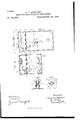
- Figure l. is a front elevation of a lock constructed according to my improvement.
- Fig. 2 is a broken front elevation thereof with parts in section.
- Fig. 3 is a cross-section on line as fr of Fig. 2.
- Fig. 4 is ahorizontal section on line y y of Fig. l, and Fig. is a vertical section on line e' e' of Fig. 4..
- the safety attachment located within the keyhole is so constructed as to be operated by the insertion of a key or other metallic or conducting article.
- a second safety attachment is arranged to be operated by the locking-bolt in such a manner as to close the circuit when the bolt is drawn into the casing of the lock.
- the attachment wit-hin the keyhole consists of two half-sleeves d l), which are secured to the keyhole-sleeve c, but insulated therefrom and from each other, the said half-sleeves being spaced at their ends, as will be seen best in Figs. l and 5.
- Each of the sleeves is connected to one of the wires of the circuit, (see Fig. 1,) and in the said circuit is arranged a signaling apparatus of any suitable kind, an electric bell being ⁇ indicated at d.
- the second safety attachment (asillustrated in Figs. l, 2, and 3, consists of a spring f, which is secured to the rear wall g of the casing e of the lock, the spring being insulated from the casing. At the front end of the spring is secured a block 7L of insulating material, the end of the spring projecting in advance of the said block, as illustrated at z'.
- the spring f is connected to one pole of the battery, and the casing c, with which the bolt 7c is permanently in contact, connects with the other pole of the battery, the bell d or other signaling device being included in such circuit.
- the circuit will be closed and the signaling device actuated.
- the free end t' of the spring f is preferably turned upon itself, as shown, whereby a good engagement of the spring with the bolt 7e is obtained without undue friction between said parts.
- the improved safety arrangement is very simple in construction and affords ample protection against burglars, as even in case the lock should be broken open it will be next to impossible to do that without moving the bolt lo inward and thereby actuating the signal.
Landscapes
- Adornments (AREA)
Description
l (No Model.)
A. J. MGULART. LOCK WITH ELECTRIC SAFETY ATTACHMENT.
Patentedct. 20, 1896.
m: Nnsms Ptrnns co, mow-Limo.. WASHINGTON. u. c.
UNITED STATES ADRIEN I. MOULART,
PATENT @Erica OF PARIS, FRANCE.
LOCK WITH ELECTRIC SAFETY ATTACHMENT.
SPECIFICATION forming part of Letters :Patent` No. 569,882', dated October 20, 1396.
Application filed June 6, 1895. Serial No. 551,920. (No model.)
To all whom, t may con/cern:
Be it known that I, ADRIEN JOSEPH MOU- LAET, a citizen of the French Republic, and a resident of Paris, France, have invented a newand Improved Lock with Electric Safety Arrangement, of which the following is a full, clear, and exact description.
My invention relates to a safety attachment for locks of any description, and has for its obj ect to provide means whereby a signal will be given every time the lock is opened.
The invention comprises an arrangement of parts whereby when a key or other tool is inserted in the keyhole an electric circuit will be closed and a signaling apparatus included in such circuit will be operated. The .invention also comprises an arrangement of parts whereby an electrical signaling device will be actuated whenever the bolt of the lock is moved inward.
Reference is to be had to the accompanying drawings, forming a part of this specification, in which similar characters of reference indicate corresponding` parts in all the views.
Figure l. is a front elevation of a lock constructed according to my improvement. Fig. 2 is a broken front elevation thereof with parts in section. Fig. 3 is a cross-section on line as fr of Fig. 2. Fig. 4 is ahorizontal section on line y y of Fig. l, and Fig. is a vertical section on line e' e' of Fig. 4..
The safety attachment located within the keyhole is so constructed as to be operated by the insertion of a key or other metallic or conducting article. A second safety attachment is arranged to be operated by the locking-bolt in such a manner as to close the circuit when the bolt is drawn into the casing of the lock.
The attachment wit-hin the keyhole consists of two half-sleeves d l), which are secured to the keyhole-sleeve c, but insulated therefrom and from each other, the said half-sleeves being spaced at their ends, as will be seen best in Figs. l and 5. Each of the sleeves is connected to one of the wires of the circuit, (see Fig. 1,) and in the said circuit is arranged a signaling apparatus of any suitable kind, an electric bell being` indicated at d.
It will be obvious that whenever a metallic or conducting article, such as a key or a picklock, is inserted in the keyhole the circuit will be completed by the said article bridging the gap between the half-sleeves a and b, and thus the signaling apparatus d will be actuated. An audible signal will therefore be given whenever the lock is opened, and this may be availed of as a protection against burglars.
The second safety attachment,asillustrated in Figs. l, 2, and 3, consists of a spring f, which is secured to the rear wall g of the casing e of the lock, the spring being insulated from the casing. At the front end of the spring is secured a block 7L of insulating material, the end of the spring projecting in advance of the said block, as illustrated at z'. When the lock is closed, as illustrated by Fig.'l, the bolt 7c is in contact with the insulating-block h. lVhen, however, the lock is opened, or the bolt k is moved inward in any other manner, the spring f will assume the position illustrated by Fig. 2, in which the end '1I of the spring comes in contact with the bolt 7e. The spring f is connected to one pole of the battery, and the casing c, with which the bolt 7c is permanently in contact, connects with the other pole of the battery, the bell d or other signaling device being included in such circuit. Thus it will be seen that in the position illustrated by Fig. 2 the circuit will be closed and the signaling device actuated. The free end t' of the spring f is preferably turned upon itself, as shown, whereby a good engagement of the spring with the bolt 7e is obtained without undue friction between said parts.
It will be seen that the improved safety arrangement is very simple in construction and affords ample protection against burglars, as even in case the lock should be broken open it will be next to impossible to do that without moving the bolt lo inward and thereby actuating the signal.
Having thus described my invention, I claim as new and desire to secure by Letters Patentl. In a lock, two conducting half-sleeves arranged out of contact with each other, a split keyhole-sleeve surrounding them, an insulating-sleeve between the keyhole-sleeve and the half-sleeves, and an electrically-operated signaling device in circuit with the half-sleeves, substantially as described.
ICO
and adapted to be electrically connected upon the insertion of a key or other conductingu'- ticle, :t sliding' bolt, 2L yielding Contact in conducting' contact with the bolt in one position thereof, and insulated therefrom in the other position of the bolt, an electric circuit having two branches or shunts in one ol which are included the two insulated parts of the keyi hole while in the other parallel branch or shunt are included the bolt and its yielding Contact, and in electrically-operated signaling device in said circuit, substantially :is described.
In witness whereof I lia-ve hereunto sct my hund in presence of two witnesses.
ADRIEN J. MOULXRT. Witnesses:
G. SOUZAY, ANDRILLOS.
Publications (1)
| Publication Number | Publication Date |
|---|---|
| US569882A true US569882A (en) | 1896-10-20 |
Family
ID=2638586
Family Applications (1)
| Application Number | Title | Priority Date | Filing Date |
|---|---|---|---|
| US569882D Expired - Lifetime US569882A (en) | moulart |
Country Status (1)
| Country | Link |
|---|---|
| US (1) | US569882A (en) |
-
0
- US US569882D patent/US569882A/en not_active Expired - Lifetime
Similar Documents
| Publication | Publication Date | Title |
|---|---|---|
| US1774636A (en) | Electric lock | |
| US521239A (en) | Burglar-alarm | |
| US499428A (en) | Electric hinge | |
| US1836452A (en) | Electric signal | |
| US783014A (en) | Burglar-alarm. | |
| US715334A (en) | Electric safe-lock. | |
| US516478A (en) | Electric lock | |
| US1047105A (en) | Alarm-lock. | |
| US1212632A (en) | Combined switch and lock device. | |
| US1122010A (en) | Lock circuit-closer. | |
| US880168A (en) | Combined lock and electric switch. | |
| US262393A (en) | James p | |
| US867220A (en) | Circuit-closer for door-alarms. | |
| US739272A (en) | Electric alarm-lock. | |
| US560043A (en) | Adrien j | |
| US460391A (en) | Electric lock | |
| US516239A (en) | Charles f | |
| US1139152A (en) | Burglar-alarm lock. | |
| US491426A (en) | holcombe | |
| US490161A (en) | Electric alarm-lock | |
| US622177A (en) | Electrical knob | |
| US1627357A (en) | Electric-circuit-controlling apparatus | |
| US869462A (en) | Alarm dead-lock. | |
| US1096935A (en) | Burglar-alarm for door-knobs. | |
| US830780A (en) | Circuit-closer for locks. |