US5685374A - Well completions in weakly consolidated formations - Google Patents
Well completions in weakly consolidated formations Download PDFInfo
- Publication number
- US5685374A US5685374A US08/601,192 US60119296A US5685374A US 5685374 A US5685374 A US 5685374A US 60119296 A US60119296 A US 60119296A US 5685374 A US5685374 A US 5685374A
- Authority
- US
- United States
- Prior art keywords
- solids
- zone
- fluid
- well
- formation
- Prior art date
- Legal status (The legal status is an assumption and is not a legal conclusion. Google has not performed a legal analysis and makes no representation as to the accuracy of the status listed.)
- Expired - Lifetime
Links
- 230000015572 biosynthetic process Effects 0.000 title claims abstract description 95
- 238000005755 formation reaction Methods 0.000 title description 75
- 239000012530 fluid Substances 0.000 claims abstract description 155
- 239000007787 solid Substances 0.000 claims abstract description 114
- 238000004519 manufacturing process Methods 0.000 claims abstract description 72
- 238000000034 method Methods 0.000 claims abstract description 48
- 239000000203 mixture Substances 0.000 claims abstract description 48
- 229930195733 hydrocarbon Natural products 0.000 claims abstract description 17
- 150000002430 hydrocarbons Chemical class 0.000 claims abstract description 17
- 239000004215 Carbon black (E152) Substances 0.000 claims abstract description 16
- 239000002002 slurry Substances 0.000 claims abstract description 13
- 239000002245 particle Substances 0.000 claims abstract description 10
- 230000000977 initiatory effect Effects 0.000 claims abstract description 5
- 230000000149 penetrating effect Effects 0.000 claims abstract description 5
- 230000007423 decrease Effects 0.000 claims abstract description 4
- 238000002347 injection Methods 0.000 claims description 18
- 239000007924 injection Substances 0.000 claims description 18
- 239000007788 liquid Substances 0.000 claims description 11
- 238000004891 communication Methods 0.000 claims description 6
- 238000012544 monitoring process Methods 0.000 claims description 4
- 230000004936 stimulating effect Effects 0.000 claims description 3
- 230000001815 facial effect Effects 0.000 claims description 2
- 230000035699 permeability Effects 0.000 claims description 2
- 238000005086 pumping Methods 0.000 claims description 2
- 230000000694 effects Effects 0.000 claims 1
- 238000000926 separation method Methods 0.000 description 13
- 239000004576 sand Substances 0.000 description 11
- 239000010779 crude oil Substances 0.000 description 6
- 238000003860 storage Methods 0.000 description 5
- XLYOFNOQVPJJNP-UHFFFAOYSA-N water Substances O XLYOFNOQVPJJNP-UHFFFAOYSA-N 0.000 description 5
- 239000003921 oil Substances 0.000 description 4
- 230000008569 process Effects 0.000 description 4
- 238000010586 diagram Methods 0.000 description 3
- 238000012986 modification Methods 0.000 description 3
- 230000004048 modification Effects 0.000 description 3
- 238000012545 processing Methods 0.000 description 3
- 230000008901 benefit Effects 0.000 description 2
- 230000001276 controlling effect Effects 0.000 description 2
- 238000011161 development Methods 0.000 description 2
- 238000005553 drilling Methods 0.000 description 2
- 230000001965 increasing effect Effects 0.000 description 2
- 238000011084 recovery Methods 0.000 description 2
- 241001427367 Gardena Species 0.000 description 1
- 238000004458 analytical method Methods 0.000 description 1
- 238000004364 calculation method Methods 0.000 description 1
- 238000007596 consolidation process Methods 0.000 description 1
- 238000010276 construction Methods 0.000 description 1
- 238000007796 conventional method Methods 0.000 description 1
- -1 crude oil Chemical class 0.000 description 1
- 230000001419 dependent effect Effects 0.000 description 1
- 238000009826 distribution Methods 0.000 description 1
- 230000002708 enhancing effect Effects 0.000 description 1
- 238000010438 heat treatment Methods 0.000 description 1
- 230000002401 inhibitory effect Effects 0.000 description 1
- 238000009434 installation Methods 0.000 description 1
- 238000002955 isolation Methods 0.000 description 1
- 230000007246 mechanism Effects 0.000 description 1
- 238000012856 packing Methods 0.000 description 1
- 238000010951 particle size reduction Methods 0.000 description 1
- 239000003208 petroleum Substances 0.000 description 1
- 239000002952 polymeric resin Substances 0.000 description 1
- 230000001105 regulatory effect Effects 0.000 description 1
- 230000000638 stimulation Effects 0.000 description 1
- 239000000126 substance Substances 0.000 description 1
- 238000006467 substitution reaction Methods 0.000 description 1
- 229920003002 synthetic resin Polymers 0.000 description 1
- 238000012360 testing method Methods 0.000 description 1
Images


Classifications
-
- E—FIXED CONSTRUCTIONS
- E21—EARTH OR ROCK DRILLING; MINING
- E21B—EARTH OR ROCK DRILLING; OBTAINING OIL, GAS, WATER, SOLUBLE OR MELTABLE MATERIALS OR A SLURRY OF MINERALS FROM WELLS
- E21B43/00—Methods or apparatus for obtaining oil, gas, water, soluble or meltable materials or a slurry of minerals from wells
- E21B43/29—Obtaining a slurry of minerals, e.g. by using nozzles
-
- E—FIXED CONSTRUCTIONS
- E21—EARTH OR ROCK DRILLING; MINING
- E21B—EARTH OR ROCK DRILLING; OBTAINING OIL, GAS, WATER, SOLUBLE OR MELTABLE MATERIALS OR A SLURRY OF MINERALS FROM WELLS
- E21B41/00—Equipment or details not covered by groups E21B15/00 - E21B40/00
- E21B41/005—Waste disposal systems
- E21B41/0057—Disposal of a fluid by injection into a subterranean formation
-
- E—FIXED CONSTRUCTIONS
- E21—EARTH OR ROCK DRILLING; MINING
- E21B—EARTH OR ROCK DRILLING; OBTAINING OIL, GAS, WATER, SOLUBLE OR MELTABLE MATERIALS OR A SLURRY OF MINERALS FROM WELLS
- E21B43/00—Methods or apparatus for obtaining oil, gas, water, soluble or meltable materials or a slurry of minerals from wells
- E21B43/34—Arrangements for separating materials produced by the well
- E21B43/35—Arrangements for separating materials produced by the well specially adapted for separating solids
-
- E—FIXED CONSTRUCTIONS
- E21—EARTH OR ROCK DRILLING; MINING
- E21B—EARTH OR ROCK DRILLING; OBTAINING OIL, GAS, WATER, SOLUBLE OR MELTABLE MATERIALS OR A SLURRY OF MINERALS FROM WELLS
- E21B43/00—Methods or apparatus for obtaining oil, gas, water, soluble or meltable materials or a slurry of minerals from wells
- E21B43/34—Arrangements for separating materials produced by the well
- E21B43/40—Separation associated with re-injection of separated materials
Definitions
- the present invention pertains to a method for completing a fluid production well in a weakly consolidated formation by allowing the production of solids fines from the near wellbore region to generate a cavity which will increase effective wellbore radius and result in enhanced production from a formation.
- the produced solids are separated and processed for reinjection into a disposal well, for example.
- One widely used conventional method of producing fluids from relatively weakly consolidated formations is to install a solids separation system in the wellbore adjacent the formation zone being produced.
- Such systems usually comprise a so-called gravel packing wherein a slotted conduit or liner is inserted in the wellbore and a layer of relatively coarse sand or gravel is packed around this conduit to act as a filter to prevent the production of sand and other solids fines into the well for recovery with the production fluid.
- Conventional sand control techniques such as gravel pack installations and the injection of polymer resins into the formation production zone, for example, can reduce fluid production rates by as much as 75% of expected recovery rates and may significantly reduce total production of fluids from a weakly consolidated formation.
- the present invention provides a unique method for producing fluids from wells penetrating weakly consolidated subterranean earth formations.
- the method contemplates improvements in the production rates of hydrocarbon fluids from weakly consolidated formations, namely, formations generally having a cohesive strength of less than about 2000 psi and more preferably less than about 500 psi, for example.
- fluids are produced from weakly consolidated earth formations by allowing or stimulating the production of fluid together with formation fines at a rate which will generate a near wellbore cavity in the vicinity of a perforated casing or even a so-called open hole wellbore. Fluid production is caused to occur at a rate which will allow the wellbore cavity to increase until the fluid velocity across the cavity face decreases below that which is required to transport particulate solids from the formation to the well thereby inhibiting further growth of the cavity.
- a method of producing hydrocarbon fluids from weakly consolidated formations wherein a cavity is formed in the formation in the near wellbore region, which cavity increases the effective wellbore radius and thus leads to even higher fluid production rates.
- Such a process is particularly advantageous for producing fluids from formations which have a cohesive strength less than about 500 psi and which are occupied by a relatively heavy and substantially dead formation fluid, such as crude oil.
- a method for completing and producing fluids from a weakly consolidated formation by a well penetrating the formation wherein solids produced with the production fluid (sand, formation fines, etc.) are separated at the surface from the produced fluid and at least a portion of the produced fluid may be used as a power fluid in a hydraulic jet pump, for example, to provide artificial lift for the production fluid.
- solids produced with the production fluid sand, formation fines, etc.
- fluid production may eventually require artificial lift from a hydraulic jet pump using a power fluid such as crude oil, water or any other fluid which, preferably, may be compatible with or enhance the solids separation process once the produced mixture is brought to the surface.
- Artificial lift may also be provided by gas injection into the well.
- the present invention still further provides a method for completion of a well with an increased effective wellbore radius in a weakly consolidation formation by creating a cavity in the near wellbore region through controlled initial production of fluids and formation fines or sand from the near wellbore region until a cavity has developed of sufficient size wherein the cavity face area together with the rate of production of fluid results in a fluid velocity across the cavity face at a level which will not transport solids particulates from the formation to and through the well.
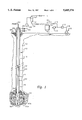
- FIG. 1 is a schematic diagram of a well penetrating a weakly consolidated earth formation and adapted to produce fluids from the formation to generate a cavity in the production zone;
- FIG. 2 is a section view taken along the line 2--2 of FIG. 1 and showing the conditions of the formation at the onset of production of fluids and particulate solids into the wellbore;
- FIG. 3 is a view taken from the same line as FIG. 2 and showing the growth of the cavity in the near wellbore region of the formation to a size wherein fines are still being produced from the formation into the well;
- FIG. 4 is a view taken from the same line as the views of FIG. 2 and FIG. 3 and showing the size of the cavity at which the production of solids and cavity growth is substantially complete;
- FIG. 5 is a schematic diagram similar in some respects to FIG. 1 and showing a system for artificial lift of production fluid from the well;
- FIG. 6 is a schematic diagram of a well such as shown in FIGS. 1 and 5 but including a system for generating artificial lift using pressure gas.
- FIG. 1 there is shown in somewhat schematic form a fluid production well 10 which has been drilled into an earth formation 12 including a rather weakly consolidated zone 14 containing a recoverable quantity of hydrocarbon fluid such as crude oil.
- the zone 14 may have a cohesive strength of greater than 500 psi, however, the method of the present invention is optimally implemented in producing formations having a cohesive strength generally less than 500 psi.
- One formation which, it is contemplated, can be satisfactorily produced by the method of the invention is disposed in the North Slope oil producing region of Alaska, and, in particular, includes a field known as West Sak which is disposed at a depth of 3,000 feet to 4,000 feet below the surface and has a cohesive strength in the range of 50 psi to 500 psi.
- the well 10 may include a conventional casing structure 16 having a plurality of perforations 18 formed therein to communicate a wellbore 19 with the formation zone 14.
- the well 10 also includes a conventional tubing string 22 extending from a conventional wellhead 24 and secured in the casing at the lower end of the tubing string by a conventional packer 26. If the formation pressure in the zone 14 is sufficient, the well 10 may, at least initially, be free flowing and fluid production rate controlled by a throttling valve or choke 28 interposed in a flowline 30.
- the flowline 30 is operable for conducting a mixture of produced oil and particulate solids, including sand, formation fines and other particles which are heavily dispersed in the oil.
- the flowline 30 is connected to suitable separation means 32 for separating solids particulates from fluids.
- suitable separation means 32 for separating solids particulates from fluids.
- a single stage centrifugal or cyclone type separator is illustrated.
- Other separation facilities including multi-stage centrifugal or cyclone type separators, may be utilized.
- Additional separation techniques including mixing the produced fluid with viscosity reducing and solids particle coalescing substances may be used.
- the produced fluid and particulates mixture may require heating to reduce the fluid viscosity to enhance separation.
- Production fluids separated by the separator means 32 is conducted to further processing or transport apparatus, not shown, through a flowline 34 and separated sand and other solids particulates is conducted from the separator means 32 through a conduit 36.
- additional solids separation equipment may be interposed in the conduit 36 to further strip recoverable hydrocarbon fluids from the solids particulates before mixing the solids particulates with a transport fluid, such as water, for conduction to a storage and mixing tank 38.
- the storage tank 38 may be part of a solids treatment and disposal system such as described in U.S. Pat. Nos. 5,109,933 issued May 5, 1992 and 5,129,469 issued Jul. 14, 1992, both to James E. Jackson and both assigned to the assignee of the present invention.
- a somewhat simplified version of the system described in the aforementioned patents is shown in FIG. 1 and includes a circulating and particle size reduction pump 40 connected to the storage tank 38 and to an injection pump 42.
- the pump 40 is also connected to a conduit 44 for recirculation of a slurry of particulate solids and a carrier fluid back to the storage tank 38 for mixing and for reducing the particle size of the particulate solids to a size suitable for injection into an earth formation adjacent to the formation 12 but suitably spaced therefrom to provide for isolation of the injected solids from the production reservoir zone 14.
- the injection pump 42 is connected by way of a conduit 46 to a solids slurry injection and disposal well 48 as shown schematically in FIG. 1.
- the storage and mixing tank 38 is also in communication with a source of fluid, such as water, by way of a conduit 50, for preparing a slurry of suitable characteristics for injection through the disposal well 48.
- the slurry of formation fines, sand and other particulate solids which have been reduced in particle size using the methods described in the aforementioned patents, may be injected into disposal zones in a suitable formation using the methods described in U.S. Pat. Nos. 5,226,749 issued Jul. 13, 1993 and 5,314,265 issued May 24, 1994 to Perkins and Perkins et al., respectively, and assigned to the assignee of the present invention.
- FIGS. 2, 3 and 4 which are taken along the line 2--2 of FIG. 1, show the condition of the formation zone 14 in the vicinity of the well casing 16 at various stages in the completion method of the invention. As shown in FIG. 2, initially, the formation zone 14 surrounds the casing 16 and is contiguous therewith.
- a suitable pattern of uniformly circumferentially spaced perforations 18 is provided in the casing 16 to provide inflow of the formation fluid/solids mixture or slurry to the wellbore 19 in a circumferentially uniform pattern.
- production of fluid from the formation zone 14 is controlled to be at a rate which will generate a near wellbore cavity such as the cavity 52 which will grow radially from the wellbore, as indicated in FIGS. 3 and 4, and delimited by a cavity wall 52a, FIG. 3, which is assumed to be substantially cylindrical.
- a fluid and particulates mixture will be produced from the formation zone 14 until the cavity grows to a size indicated in FIG. 4 and defined by cavity wall 52b.
- the fluid velocity across the face or cavity wall 52b is reduced to a rate which will be less than what is necessary to transport solids particles toward the wellbore 19 and the cavity size will not grow any further, however, the facial area of cavity wall 52b is substantially greater than 52a, thus increasing the effective wellbore radius with respect to central axis 11, FIG. 1, and resulting in an improved fluid production rate in accordance with the radial form of Darcy's law which is discussed further herein.
- the cavity 52 will grow until a somewhat naturally limiting condition exists when the wellbore face area is such that fluid velocity across the face is less than is required to transport solids particles to the wellbore 19.
- the cavity 52 will be generally cylindrical in form.
- the geometry of the cavity will also be dictated to some extent by the number of perforations arranged vertically and circumferentially in the casing 16.
- the cavity face 52b may become somewhat spherical in shape, again somewhat dependent on the distribution of perforations 18.
- the well 10 As the well 10 is produced, initially, to create growth of the cavity 52, the fluid and solids mixture flowing from the well will be separated in the separator means 32 and the solids particulates conveyed to the tank 38 for further processing and reinjection through the injection well 48 into a subterranean disposal zone. As the cavity 52 stabilizes in size, as indicated by the cavity shown in FIG. 4, the production of solids particulates will decrease substantially and the amount of separation required will also be reduced.
- the well 10 may then be required to be produced using artificial lift means, such as described hereinbelow.
- the well 10 may, of course, initially require production of the liquid and particulate solids mixture by artificial lift techniques and flow of formation fluid may also require some form of stimulation.
- the injection of gas, into and through injection wells arranged around the production well 10 in a suitable pattern may cause the substantially dead formation fluid to "swell", thereby effectively initiating or enhancing the flow of fluid toward the production well.
- the viscosity of the production fluid may be such as to benefit from steam or hot water injection by way of a conduit 53 connected to wellhead 24, FIG. 1, whereby alternating steam or water injection and formation fluid production cycles are carried out.
- FIG. 5 illustrates a modified arrangement of the well 10 wherein artificial lift has been implemented to stimulate and continue the production of fluid from the zone 14.
- a hydraulic jet pump 60 is shown installed at the distal end of the tubing string 22.
- the jet pump 60 may be of a type commercially available such as from TRICO Industries, Inc., Gardena, Calif.
- a high volume type C pump from the abovementioned supplier may be suitable for pumping a relatively viscous mixture of formation fluid and solids particulates.
- power fluid is conducted down through the tubing string 22 and entrains a fluid-solids mixture from the wellbore 19 for production up through the annular space 23 between the tubing string 22 and the casing 16.
- the fluid-solids mixture is then conducted by way of a conduit 62 to the solids separation means 32 and substantially solids free liquid is conducted from the separation means 32 by way of flowline 34.
- a portion of the separated fluid may be drawn off from flowline 34 through a conduit 64 to a pump 66 which is connected to tubing string 22 by way of a conduit 68. Accordingly, power fluid is reclaimed from the solids separation means 32 and reused for operating the jet pump 60.
- a conduit 70 is also connected to conduit 68 and is adapted to be connected to a source of power fluid, not shown. Suitable control valves 72 and 74 may be interposed in the conduits, as shown, for controlling the flow of power fluid to the pump 66.
- the power fluid may comprise the separated and substantially solids free crude oil produced from the well 10 and mixed with a lighter, less viscous liquid such as crude oil or a refined hydrocarbon fluid to provide a suitable power fluid for lifting the liquid-solids mixture from the wellbore 19 through the annulus 23.
- the hydraulic jet pump 60 may be of a type wherein the flow paths may be reversed from that described above, that is, power fluid is supplied through the casing annulus 23 and production flows up through the tubing string 22.
- the conduits 62 and 68 would require to be reversed as to their connecting points with the separator means 32 and the pump 66, as will be appreciated by those skilled in the art.
- Utilization of a hydraulic jet pump for lifting the relatively heavy and solids laden production fluid is considered advantageous in that the power fluid tends to dilute and enhance the flow of production fluid from the wellbore 19 and a hydraulic jet pump is less likely to be damaged by the solids content of the production fluid.
- FIG. 6 illustrates a further modification of an arrangement for producing solids laden fluid from formation zone 14 through a further modification of the well 10.
- the tubing string 22 is modified to include one or more gas lift mandrels 80 interposed therein and of conventional construction.
- the gas lift mandrels 80 are supplied with pressure gas through the annulus 23 by way of a supply conduit 82 connected to a source of pressure gas, such as a compressor 84.
- the solids laden production fluid is conducted up through the tubing string 22, including the gas lift mandrels 80, in a conventional manner and gas may be separated from the fluid mixture by a suitable separator 86 interposed in a flowline 88 connected to the wellhead 24 and in communication with the tubing string 22.
- the separator 86 may be a centrifugal type utilizing a spiral auger flite interposed in a conduit and of a type described in U.S. Pat. No. 5,431,228 issued Jul. 11, 1995 to Weingarten et al. and assigned to the assignee of the present invention.
- Gas separated from the production fluid-solids mixture is conducted by way of a conduit 90 to the compressor 84 or to another process stream, not shown. Additional gas needed for the gas lift process or for injection into the formation 12 may be supplied by a conduit 92.
- the compressor 84 is also operable to be connected to one or more injection wells 94, one shown, by way of a conduit 96 for injection of gas into the formation 12 in a suitable pattern to stimulate flow of the production fluid solids mixture toward the wellbore 19.
- the gas lift system illustrated in FIG. 6 is also advantageous for artificially lifting a solids laden fluid mixture to the surface in that problems associated with excess wear and plugging of mechanical pumps are eliminated.
- the use of injection gas and the use of gas as a lifting fluid can be advantageous in that, in certain hydrocarbon production fields, it is readily available.
- the aforedescribed systems and methods for producing fluids from a weakly consolidated earth formation zone are advantageous and unique in that the method contemplates at least an initial production of a substantial quantity of formation solids along with formation fluids. Solids separation and disposal, in particular, is enhanced by treating the solids for reinjection into an earth formation at a suitable injection well remote from the production formation.
- the operation of the embodiments shown in FIGS. 1, 5 and 6 are believed to be understandable to those of skill in the art from the foregoing description. however, briefly, once the well 10 has been drilled and cased and the casing 16 perforated to form the perforations 18, production is initiated at a controlled rate by any of the three systems described. In particular, if the well is free flowing under pressure in the formation zone 14, the flow rate of the fluid/solids mixture is controlled by a suitable valve interposed in the flow path such as the choke 28 interposed in conduit 30 at the surface of formation 12.
- a suitable pressure sensor 98 may be interposed in the wellbore 19 to sense bottom hole pressure, and ambient or nominal pressure in zone 14 may be determined at a shut-in condition of the well, also from the sensor 98.
- the sensor 98 is adapted for transmitting pressure signals to the surface for monitoring by suitable signal receiving means 99.
- the sensor 98 and the signal receiving means 99 may be of a type such as described in U.S. Pat. Nos. 4,691,203 issued Sep. 1, 1987 to Rubin et al. or 5,091,725 issued Feb. 25, 1992 to Gard, for example.
- the production flow rate of solids laden fluid may then be controlled to generate an effective wellbore radius as described above.
- the cavity size may be determined.
- the well 10 may be allowed to produce somewhat uncontrolled until the cavity size increases to a point wherein the fluid velocity across the cavity face 52b is less than the transport velocity required to entrain solids particulates from the formation zone 14. If the systems illustrated and described in conjunction with FIGS. 5 and 6 are being implemented, the production rate may be controlled by the amount of power fluid or lift gas conducted to the well 10 for operation of the artificial lift mechanisms associated therewith.
- the effective radius (r w ) of the cavity wall 52b with respect to the central axis of the well 10 may be determined from the following equation: ##EQU1## wherein q is the flow rate in standard barrels per day (42 U.S.
- Equation (a) set forth above is discussed further in "Advances in Well Test Analysis” by Robert C. Earlougher, Jr., Society of Petroleum Engineers, Richardson, Texas 1977. Accordingly, with known pressures and flow rates, the equation above may be solved for the effective wellbore radius (r w ). Conversely, the effective wellbore radius (r w ) may be limited by controlling the flow rate of fluid produced from the well.
Landscapes
- Engineering & Computer Science (AREA)
- Life Sciences & Earth Sciences (AREA)
- Geology (AREA)
- Mining & Mineral Resources (AREA)
- Environmental & Geological Engineering (AREA)
- Physics & Mathematics (AREA)
- Fluid Mechanics (AREA)
- General Life Sciences & Earth Sciences (AREA)
- Geochemistry & Mineralogy (AREA)
- Production Of Liquid Hydrocarbon Mixture For Refining Petroleum (AREA)
Abstract
Description
Claims (24)
Priority Applications (1)
| Application Number | Priority Date | Filing Date | Title |
|---|---|---|---|
| US08/601,192 US5685374A (en) | 1996-02-14 | 1996-02-14 | Well completions in weakly consolidated formations |
Applications Claiming Priority (1)
| Application Number | Priority Date | Filing Date | Title |
|---|---|---|---|
| US08/601,192 US5685374A (en) | 1996-02-14 | 1996-02-14 | Well completions in weakly consolidated formations |
Publications (1)
| Publication Number | Publication Date |
|---|---|
| US5685374A true US5685374A (en) | 1997-11-11 |
Family
ID=24406566
Family Applications (1)
| Application Number | Title | Priority Date | Filing Date |
|---|---|---|---|
| US08/601,192 Expired - Lifetime US5685374A (en) | 1996-02-14 | 1996-02-14 | Well completions in weakly consolidated formations |
Country Status (1)
| Country | Link |
|---|---|
| US (1) | US5685374A (en) |
Cited By (11)
| Publication number | Priority date | Publication date | Assignee | Title |
|---|---|---|---|---|
| US5839513A (en) * | 1997-05-22 | 1998-11-24 | Phillips Petroleum Company | Compressor-assisted annular flow |
| US6119779A (en) * | 1998-11-09 | 2000-09-19 | Atlantic Richfield Company | Method and system for separating and disposing of solids from produced fluids |
| US6164727A (en) * | 1998-12-31 | 2000-12-26 | Kelly; Melvin E. | Method of mining a soluble mineral |
| RU2179659C1 (en) * | 2000-10-12 | 2002-02-20 | Закрытое акционерное общество "НАМиКо" | Plant for preparation and delivery of working fluid to oil-well hydraulically driven pumps |
| US6668931B1 (en) | 2002-07-08 | 2003-12-30 | Jim Tomlinson | Apparatus and method for cleaning a gas well |
| US6730236B2 (en) * | 2001-11-08 | 2004-05-04 | Chevron U.S.A. Inc. | Method for separating liquids in a separation system having a flow coalescing apparatus and separation apparatus |
| US6874580B2 (en) | 2002-10-25 | 2005-04-05 | Conocophillips Company | Method for enhancing well productivity |
| US20060131029A1 (en) * | 2004-12-21 | 2006-06-22 | Zupanick Joseph A | Method and system for cleaning a well bore |
| US20080202757A1 (en) * | 2007-02-27 | 2008-08-28 | Conocophillips Company | Method of stimulating a coalbed methane well |
| EP2216384A1 (en) * | 2009-01-22 | 2010-08-11 | Weatherford/Lamb, Inc. | A process for creating enhanced cavitation |
| US20150354341A1 (en) * | 2013-02-19 | 2015-12-10 | Halliburton Energy Services Inc. | System and Method to Convert Surface Pressure to Bottom Hole Pressure Using an Integrated Computation Element |
Citations (8)
| Publication number | Priority date | Publication date | Assignee | Title |
|---|---|---|---|---|
| US4830110A (en) * | 1988-03-22 | 1989-05-16 | Atlantic Richfield Company | Method for completing wells in unconsolidated formations |
| US5109933A (en) * | 1990-08-17 | 1992-05-05 | Atlantic Richfield Company | Drill cuttings disposal method and system |
| US5129469A (en) * | 1990-08-17 | 1992-07-14 | Atlantic Richfield Company | Drill cuttings disposal method and system |
| US5226749A (en) * | 1992-07-08 | 1993-07-13 | Atlantic Richfield Company | Waste disposal in hydraulically fractured earth formations |
| US5236605A (en) * | 1992-07-07 | 1993-08-17 | Horizontal Rentals, Inc. | Method and apparatus for continuous separation of oil from solid and liquid contaminants |
| US5303786A (en) * | 1992-09-16 | 1994-04-19 | Atlantic Richfield Company | Earth drilling cuttings processing system |
| US5314265A (en) * | 1993-03-17 | 1994-05-24 | Atlantic Richfield Company | Waste disposal in hydraulically fractured earth formations |
| US5387737A (en) * | 1993-04-06 | 1995-02-07 | Atlantic Richfield Company | Slurry injection into disaggregated earth formations |
-
1996
- 1996-02-14 US US08/601,192 patent/US5685374A/en not_active Expired - Lifetime
Patent Citations (8)
| Publication number | Priority date | Publication date | Assignee | Title |
|---|---|---|---|---|
| US4830110A (en) * | 1988-03-22 | 1989-05-16 | Atlantic Richfield Company | Method for completing wells in unconsolidated formations |
| US5109933A (en) * | 1990-08-17 | 1992-05-05 | Atlantic Richfield Company | Drill cuttings disposal method and system |
| US5129469A (en) * | 1990-08-17 | 1992-07-14 | Atlantic Richfield Company | Drill cuttings disposal method and system |
| US5236605A (en) * | 1992-07-07 | 1993-08-17 | Horizontal Rentals, Inc. | Method and apparatus for continuous separation of oil from solid and liquid contaminants |
| US5226749A (en) * | 1992-07-08 | 1993-07-13 | Atlantic Richfield Company | Waste disposal in hydraulically fractured earth formations |
| US5303786A (en) * | 1992-09-16 | 1994-04-19 | Atlantic Richfield Company | Earth drilling cuttings processing system |
| US5314265A (en) * | 1993-03-17 | 1994-05-24 | Atlantic Richfield Company | Waste disposal in hydraulically fractured earth formations |
| US5387737A (en) * | 1993-04-06 | 1995-02-07 | Atlantic Richfield Company | Slurry injection into disaggregated earth formations |
Cited By (13)
| Publication number | Priority date | Publication date | Assignee | Title |
|---|---|---|---|---|
| US5839513A (en) * | 1997-05-22 | 1998-11-24 | Phillips Petroleum Company | Compressor-assisted annular flow |
| US6119779A (en) * | 1998-11-09 | 2000-09-19 | Atlantic Richfield Company | Method and system for separating and disposing of solids from produced fluids |
| US6164727A (en) * | 1998-12-31 | 2000-12-26 | Kelly; Melvin E. | Method of mining a soluble mineral |
| RU2179659C1 (en) * | 2000-10-12 | 2002-02-20 | Закрытое акционерное общество "НАМиКо" | Plant for preparation and delivery of working fluid to oil-well hydraulically driven pumps |
| US6730236B2 (en) * | 2001-11-08 | 2004-05-04 | Chevron U.S.A. Inc. | Method for separating liquids in a separation system having a flow coalescing apparatus and separation apparatus |
| US6668931B1 (en) | 2002-07-08 | 2003-12-30 | Jim Tomlinson | Apparatus and method for cleaning a gas well |
| US6874580B2 (en) | 2002-10-25 | 2005-04-05 | Conocophillips Company | Method for enhancing well productivity |
| US20060131029A1 (en) * | 2004-12-21 | 2006-06-22 | Zupanick Joseph A | Method and system for cleaning a well bore |
| US7311150B2 (en) * | 2004-12-21 | 2007-12-25 | Cdx Gas, Llc | Method and system for cleaning a well bore |
| US20080202757A1 (en) * | 2007-02-27 | 2008-08-28 | Conocophillips Company | Method of stimulating a coalbed methane well |
| US7757770B2 (en) | 2007-02-27 | 2010-07-20 | Conocophillips Company | Method of stimulating a coalbed methane well |
| EP2216384A1 (en) * | 2009-01-22 | 2010-08-11 | Weatherford/Lamb, Inc. | A process for creating enhanced cavitation |
| US20150354341A1 (en) * | 2013-02-19 | 2015-12-10 | Halliburton Energy Services Inc. | System and Method to Convert Surface Pressure to Bottom Hole Pressure Using an Integrated Computation Element |
Similar Documents
| Publication | Publication Date | Title |
|---|---|---|
| US6039116A (en) | Oil and gas production with periodic gas injection | |
| US10689964B2 (en) | Systems and apparatuses for separating wellbore fluids and solids during production | |
| US6119779A (en) | Method and system for separating and disposing of solids from produced fluids | |
| US6125936A (en) | Dual completion method for oil/gas wells to minimize water coning | |
| US4793408A (en) | Device for separating and extracting components having different densities from an effluent | |
| EP0815349A1 (en) | Hydrocarbon production using multilateral well bores | |
| US4512405A (en) | Pneumatic transfer of solids into wells | |
| US5226749A (en) | Waste disposal in hydraulically fractured earth formations | |
| US4842068A (en) | Process for selectively treating a subterranean formation using coiled tubing without affecting or being affected by the two adjacent zones | |
| US10669833B2 (en) | Systems and apparatuses for separating wellbore fluids and solids during production | |
| US4878539A (en) | Method and system for maintaining and producing horizontal well bores | |
| GB2327695A (en) | Hydrocarbon production using multilateral wellbores. | |
| US7370701B2 (en) | Wellbore completion design to naturally separate water and solids from oil and gas | |
| US5685374A (en) | Well completions in weakly consolidated formations | |
| US4532994A (en) | Well with sand control and stimulant deflector | |
| US20060076140A1 (en) | Gas Lift Apparatus and Method for Producing a Well | |
| US2986215A (en) | Salt water disposal system | |
| US6053249A (en) | Method and apparatus for injecting gas into a subterranean formation | |
| US20250154860A1 (en) | Downhole processing and disposal of produced solids from a well | |
| US6668931B1 (en) | Apparatus and method for cleaning a gas well | |
| US3743021A (en) | Method for cleaning well perforations | |
| US11506042B2 (en) | Downhole production fluid fractionation system | |
| US20200256179A1 (en) | Systems and apparatuses for downhole separation of gases from liquids | |
| US10858924B2 (en) | Systems for improving downhole separation of gases from liquids while producing reservoir fluid | |
| US3483926A (en) | Consolidation of oil-bearing formations |
Legal Events
| Date | Code | Title | Description |
|---|---|---|---|
| AS | Assignment |
Owner name: ATLANTIC RICHFIELD COMPANY, TEXAS Free format text: ASSIGNMENT OF ASSIGNORS INTEREST;ASSIGNORS:SCHMIDT, JOSEPH H.;BERGREN, FRANK E.;BILL, MICHAEL I.;AND OTHERS;REEL/FRAME:008452/0909;SIGNING DATES FROM 19960130 TO 19960206 |
|
| STCF | Information on status: patent grant |
Free format text: PATENTED CASE |
|
| FEPP | Fee payment procedure |
Free format text: PAYOR NUMBER ASSIGNED (ORIGINAL EVENT CODE: ASPN); ENTITY STATUS OF PATENT OWNER: LARGE ENTITY |
|
| FPAY | Fee payment |
Year of fee payment: 4 |
|
| AS | Assignment |
Owner name: PHILLIPS PETROLEUM COMPANY, OKLAHOMA Free format text: ASSIGNMENT OF ASSIGNORS INTEREST;ASSIGNOR:ATLANTIC RICHFIELD COMPANY;REEL/FRAME:012333/0329 Effective date: 20010920 |
|
| FPAY | Fee payment |
Year of fee payment: 8 |
|
| FPAY | Fee payment |
Year of fee payment: 12 |
|
| AS | Assignment |
Owner name: CONOCOPHILLIPS COMPANY, TEXAS Free format text: CHANGE OF NAME;ASSIGNOR:PHILLIPS PETROLEUM COMPANY;REEL/FRAME:022793/0106 Effective date: 20021212 |