US5675808A - Power control of circuit modules within an integrated circuit - Google Patents
Power control of circuit modules within an integrated circuit Download PDFInfo
- Publication number
- US5675808A US5675808A US08/333,537 US33353794A US5675808A US 5675808 A US5675808 A US 5675808A US 33353794 A US33353794 A US 33353794A US 5675808 A US5675808 A US 5675808A
- Authority
- US
- United States
- Prior art keywords
- circuit
- bit
- register
- clock
- address
- Prior art date
- Legal status (The legal status is an assumption and is not a legal conclusion. Google has not performed a legal analysis and makes no representation as to the accuracy of the status listed.)
- Expired - Lifetime
Links
Images


Classifications
-
- H—ELECTRICITY
- H03—ELECTRONIC CIRCUITRY
- H03K—PULSE TECHNIQUE
- H03K23/00—Pulse counters comprising counting chains; Frequency dividers comprising counting chains
- H03K23/64—Pulse counters comprising counting chains; Frequency dividers comprising counting chains with a base or radix other than a power of two
- H03K23/68—Pulse counters comprising counting chains; Frequency dividers comprising counting chains with a base or radix other than a power of two with a base which is a non-integer
-
- G—PHYSICS
- G06—COMPUTING OR CALCULATING; COUNTING
- G06F—ELECTRIC DIGITAL DATA PROCESSING
- G06F7/00—Methods or arrangements for processing data by operating upon the order or content of the data handled
- G06F7/02—Comparing digital values
- G06F7/026—Magnitude comparison, i.e. determining the relative order of operands based on their numerical value, e.g. window comparator
Definitions
- This invention relates generally to methods and circuitry for controlling power consumption in large scale integrated circuits.
- the preferred embodiment of the present invention relates to controlling power consumption in a very large scale integrated circuit used to provide enhanced audio capabilities for personal computers.
- Prior art solutions do not provide the capability to independently manage power to various portions of VLSI circuits, nor the capability to maintain readability of on-circuit registers while operating in a reduced power mode. These are highly desirable features for VLSI circuits used in personal computer systems, especially portable systems. Furthermore, such prior systems do not provide either multiple modes of power reduction or glitch suppression on reactivation.
- the circuit and method of the present invention provide the capability to independently manage power provided to portions or modules of a VLSI circuit and the capability to maintain readability of on-chip registers during reduced power operation.
- the present invention further provides reduced power external memory refresh signals without utilizing the circuit's main oscillators.
- FIG. 1 is a schematic architectural overview of the basic modules of the circuit C
- FIG. 2 is a schematic illustration of the physical layout of circuit C
- FIGS. 3A and 3B is a table summarizing pin assignments for the circuit C
- FIGS. 4A and 4B is an alternative layout diagram for the circuit C; noise and a primary clock signal employed by the circuit C;
- FIG. 5 a table summarizing pin assignments for the circuit C grouped by module
- FIG. 6 is a schematic illustration of a typical full-featured implementation of a PC audio circuit C with associated circuits, buses and interconnections;
- FIG. 7 is table summarizing pin assignments and functions that relate to local memory control
- FIGS. 8A-10B comprise a table of register mnemonics with indexes and module assignments where appropriate;
- FIG. 11 is a schematic diagram illustrating an example of multiplexing circuitry
- FIG. 12 is a block diagram schematic illustration of the system control module of the circuit C
- FIG. 13 is a schematic block diagram of the circuit C including modular interfaces to the register data bus;
- FIG. 14 is a schematic diagram of implementation detailed for the register data bus
- FIG. 14a is a schematic diagram of a portion of the ISA bus interface circuitry
- FIG. 15 is a timing diagram illustrating worse case ISA-bus timing for the circuit C
- FIG. 16 is a timing diagram relating to buffered input and outputs for the circuit C
- FIG. 16a is a schematic diagram of a portion of the emulation logic for the circuit C
- FIG. 16b is a schematic block diagram of circuit access possibilities for application software and emulation TSR programs
- FIG. 17 is a schematic illustration of the Plug-n-Play state machine included within the circuit C;
- FIG. 18 is a timing diagram relating to reading serial EEPROM data from external circuitry relating to Plug-n-Play compatibility
- FIG. 19 is a schematic illustration of a circuit for facilitating PNP data transfer from external circuitry to the circuit C via the register data bus;
- FIG. 20 is a schematic illustration of a linear feed back shift register necessary to implement an initiation key for access to Plug-n-Play registers;
- FIG. 21 is a flow chart illustrating the manner in which the Plug-n-Play circuitry associated with the circuit C transitions from isolation mode to either configuration mode or sleep mode;
- FIG. 22 is a table summarizing resources required for programming the Plug-n-Play serial EEPROM
- FIG. 23 is a table providing data on all interrupt-causing events in the circuit C
- FIG. 24 is a schematic illustration of external oscillators and stabilizing logic associated therewith utilized by the circuit C;
- FIGS. 24A-1 and 24A-2 is a schematic illustration of logic and counter circuits associated with various low power modes of the circuit C;
- FIGS. 24B-1 and 24B-2 is a flow chart illustrating the response of circuit C to suspend mode operation
- FIGS. 24C-1, 24C-2 and 24C-3 is a flow chart illustrating the various register-controlled low power modes of the circuit C;
- FIG. 25 is a schematic illustration of details of the clock oscillator stabilization logic of FIG. 24;
- FIG. 26 is a table describing events which occur in response to various power conservation modes enabled via the status of bits in register PPWRI contained within the circuit C;
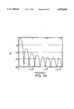
- FIG. 27 is a timing diagram showing the relationship between various power conservation modes and signals and clock signals utilized by the circuit C;
- FIGS. 28A and 28 B is a table summarizing pins associated with the system bus interface included in the circuit C;
- FIG. 29 is a block diagram schematically illustrating the basic modules which comprise the local memory control module of the circuit C;
- FIG. 30 is a block diagram schematically illustrating the master state machine associated with the local memory control module of the circuit C;
- FIG. 31 is a timing diagram illustrating the relationship of suspend mode control signals and a 32 KHz clock signal utilized by the circuit C;
- FIG. 32 is a state diagram schematically illustrating refresh cycles utilized by the circuit C during suspend mode operation
- FIG. 33 is a timing diagram for suspend mode refresh cycles
- FIG. 34a is a timing diagram for 8-bit DRAM accesses
- FIG. 34b is a timing diagram for 16-bit DRAM accesses
- FIG. 34c is a timing diagram for DRAM refresh cycles
- FIG. 35 is a timing diagram illustrating how real addresses are provided from the circuit C to external memory devices
- FIG. 36 is a schematic block diagram of a control circuit for local memory record and playback FIFOs
- FIG. 37 is a diagram illustrating the relationship between data stored in system memory and interleaved in local memory via the circuit C;
- FIG. 38 is a table describing data transfer formats for 8 and 16-bit sample sizes under DMA control
- FIG. 39 is a schematic block diagram illustrating circuitry for implementing interleaved DMA data from system memory to local memory via the local memory control module of the circuit C;
- FIG. 40 is a schematic block illustration of the game port interface between external devices and the circuit C;
- FIG. 41 is a schematic block illustration of a single bit implementation for the game input/output port of the circuit C;
- FIG. 41a is a diagram illustrating input signal detection via the game port of the circuit C
- FIG. 42 is a schematic block diagram illustrating the MIDI transmit and receive ports for the circuit C;
- FIG. 43 is a timing diagram illustrating the MIDI data format utilized by the circuit C.
- FIG. 44 is a block diagram of the various functional blocks of the CODEC module of the present invention.
- FIG. 45 is a schematic of the preferred embodiment of the left channel stereo mixer of the present invention.
- FIGS. 45A-1 and 45A-2 is a table of gain and attenuation values.
- FIG. 46 is a diagram of a partial wave form indicating signal discontinuities for attenuation/gain changes
- FIG. 47 is a block diagram showing zero detect circuits for eliminating "zipper" noise
- FIG. 48 is a block diagram showing clock generation functions in the present invention.
- FIG. 49 is a block diagram of serial data transfer functions of the present invention.
- FIG. 49a is a block diagram of the serial transfer control block
- FIG. 50 is a block diagram showing internal and external data paths and interfacing with external devices, supported by the present invention.
- FIG. 51 is a block diagram of the digital to analog converter block of the present invention.
- FIG. 52 is a block diagram of the front end of the digital to analog converter block of the present invention.
- FIGS. 53a-53f are graphs showing outputs of various stages of the DAC block, including frequency response
- FIG. 54 shows six graphs representing outputs and frequency response of various stages of the DAC block
- FIG. 55 is a schematic representation of the Interp.1 block, phase 1 of FIG. 52;
- FIG. 56 is a schematic representation of the Interp.1 block, phase 2 of FIG. 52;
- FIG. 57 is a schematic representation of the Interp.2 block of FIG. 52;
- FIG. 58 is a graph of the frequency response of the Interp.2 block of FIG. 52;
- FIG. 59 is a graph representing the in-band rolloff of the Interp.2 block of FIG. 52;
- FIG. 60 is a schematic representation of an embodiment of the Interp.3 block of FIG. 52;
- FIG. 61 is a schematic representation of another embodiment of the Interp.3 block of FIG. 52;
- FIG. 62a is a graph of the frequency response of the Interp.3 block of FIG. 52;
- FIG. 62b is a graph of the passband rolloff of the Interp.3 block of FIG. 52;
- FIG. 63 is a schematic representation of the noise shaper block of FIG. 52;
- FIG. 64 is a signal flow graph (SFG) of the noise shaper block in FIG. 52;
- FIG. 65 is a plot of the poles and zeros in the s plane for the noise shaper block of FIG. 52;
- FIG. 66 is a plot of the transfer function magnitude of the noise shaper block of FIG. 52;
- FIG. 67 is a plot of the poles and zeros in the z plane of the noise shaper block of FIG. 52;
- FIG. 68 is a graph of the transfer function of the noise shaper filter of FIG. 52;
- FIG. 69 a plot of the ideal and realizable zeros of the noise filter block of FIG. 52;
- FIG. 70 is a plot comparing two embodiments of noise transfer functions for the noise shaper block of FIG. 52;
- FIG. 71 is a plot of the noise and signal transfer functions of the noise shaper block of FIG. 52;
- FIG. 72 is a plot of the signal transfer function magnitude in phase and passband of the noise shaper block of FIG. 52;
- FIG. 73 is a graph of the group delay (sec.) of the noise shaper block of FIG. 52;
- FIG. 74 is a graph of the constant attenuation/gain contours of various embodiments of the noise shaper block of FIG. 52;
- FIG. 75 plots A max versus noise gain k for an embodiment of the noise shaper block of FIG. 52.
- FIG. 77 is a graph showing the impulse response of the D/A FIR filter
- FIG. 78 is a graph showing the frequency response of the D/A FIR filter
- FIG. 79 schematically illustrates one embodiment of the D/A conversion circuit of the present invention.
- FIGS. 80 and 81 schematically illustrate another embodiment showing the differential D/A conversion circuit of the present invention.
- FIG. 82 is a block diagram of the CODEC ADC of the present invention.
- FIG. 83 is a block diagram of the front end of the CODEC ADC
- FIG. 84 is a graph illustrating the sigma-delta modulator output spectrum-range and phase for the ADC of the present invention.
- FIG. 85 is a graph illustrating the sigma-delta modulator output spectrum, in detail.
- FIG. 86 is a graph illustrating the output spectrum of the sinc6 Decim.1 filter output
- FIG. 87 is a graph illustrating the output spectrum of the half-band Decim.2 filter output
- FIG. 88 is a graph illustrating the output spectrum of the 16-bit Decim.3 filter output
- FIG. 89 is a block diagram of the Decim.1 filter
- FIG. 90 graphically illustrates the frequency response of the Decim.1 filter
- FIG. 91 graphically illustrates a detailed frequency response of the Decim.1 filter
- FIG. 92 is a block diagram of the half-band Decim.2 filter-direct form
- FIG. 93 is a block diagram of the half-band Decim.2 filter-transposed form
- FIG. 94 graphically illustrates the frequency response of the Decim.2 filter
- FIG. 95 is a detailed frequency response graph of the Decim.2 filter
- FIG. 96 is a block diagram of the compensation filter of the CODEC D/A conversion circuitry
- FIG. 97 graphically illustrates the frequency response of the Decim.3 filter
- FIG. 98 graphically illustrates, in detail, the frequency response of the Decim.3 filter
- FIG. 99 graphically illustrates the compensator circuit frequency response (un-compensated).
- FIG. 100 graphically illustrates the total frequency response of the compensator circuitry in passband (un-compensated).
- FIG. 101 graphically illustrates the total frequency response of the compensator in passband (compensated).
- FIG. 102 is a block diagram of the synthesizer module of the present invention.
- FIG. 103 illustrates signal flow in the synthesizer module of the present invention
- FIGS. 104a-104f are graphs illustrating addressing control options in the synthesizer module of the present invention.
- FIGS. 105a-104e are graphs illustrating volume control options in the synthesizer module of the present invention.
- FIGS. 106a and 106b are graphs of low frequency oscillator waveforms available for the synthesizer module of the present invention.
- FIGS. 107A and 107B is an architectural diagram of an address controller of the synthesizer module of the present invention.
- FIGS. 108a and 108b are timing diagrams of the operations performed by the address controller of FIG. 107;
- FIGS. 109A-109C is an architectural diagram of a volume controller of the synthesizer module of the present invention.
- FIG. 110 is a timing diagram of the operations performed by the volume controller of FIG. 109;
- FIG. 111 is an architectural drawing of the register array of the synthesizer module of the present invention.
- FIG. 112 is a timing chart of the operations of the register array in FIG. 111;
- FIG. 113 is an architectural drawing of the overall volume control circuitry of the synthesizer module of the preset invention.
- FIG. 114a is a logic diagram of a comparator illustrated in FIG. 113;
- FIG. 114b is a timing chart of the operations of the comparator in FIG. 114a;
- FIG. 115 an architectural drawing of the LFO generator of the synthesizer module of the present invention.
- FIGS. 116A and 116B is an architectural diagram of the signal path of the synthesizer module of the present invention.
- FIG. 117 is a timing diagram of the operations performed by the signal path of FIG. 116;
- FIG. 118 is an architectural diagram of accumulation logic of the synthesizer module of the present invention.
- FIG. 119 is a timing diagram of the operations performed by the accumulation logic of FIG. 118.
- FIGS. 120A-120C is a timing diagram of the overall operations performed by the synthesizer module of the present invention.
- Timers can be readily implemented by providing a clock signal derived from external oscillator signals to an appropriate logic circuit.
- An 80 microsecond clock signal can be provided by dividing the 16.9 MHz oscillator signal by 1344 for example.
- the generation of control signals which respond to the status of various bits of data held in registers throughout the circuit C is a simple matter of providing control inputs to blocks or arrays of gate circuits to satisfy the required input/output or truth table requirements. Consequently, these details, where not considered significant to the claimed invention, need not and have not been provided since such matters are clearly within the level or ordinary skill in the art.
- the circuit C includes five basic modules: a system control module 2; a coder-decoder (CODEC) module 4; a synthesizer module 6; a local memory control module 8; and MIDI and game port module 10. These modules are formed on a monolithic integrated circuit.
- a register data bus 12 provides communication of data between modules and between circuit C and a system bus interface 14. Timing and control for circuit C is provided by logic circuits within system control module 2 operating in response to clock signals provided by one or both oscillators 16 and 18 depending upon the particular system requirement. Control of circuit C is generally determined by logic circuits included within module 2 which are in turn controlled by the state of various registers and ports provided throughout the circuit C.
- FIG. 1 is a functional block diagram and does not correspond directly to a physical layout for the integrated circuit embodiment.
- Various circuits, interconnects, registers etc. which provide or facilitate the functions specified in FIG. 1 may be formed in several locations spread throughout the integrated circuit as needed or as dictated by manufacturing processes, convenience or other reasons known to those of ordinary skill in the art.
- the circuit of the present invention may be fully integrated using conventional integration processes such as are well known in the industry.
- the circuit of the present invention is packaged in a 160 pin plastic quad flat pack (PQFP), as will be described in more detail below.
- PQFP 160 pin plastic quad flat pack
- the physical layout of the various modules and the pin-out arrangement have been designed to isolate analog circuits and inputs/outputs from the noisier digital circuitry and pins.
- FIG. 2 an example of the desired physical layout relationship among various portions or modules of the circuit C is schematically illustrated.
- the most noise sensitive elements of circuit C e.g., those associated with the analog aspects of the CODEC, specifically the mixer block, are located near the circuit edge opposite the largely digital local memory control and synthesizer modules.
- the pin-out arrangement of the package isolates analog mixer input and output pins in a group 20 as far removed as possible from the noisiest digital output pins and clock inputs, which are located on the opposite side 22. Furthermore, the most sensitive pin group 20 is flanked by less noisy inputs in regions 26 and 28.
- Representative pin assignments are given in FIGS. 3A and 3B, where pin names correspond to industry standard designations, such as the ISA Plug-n-Play specification, version 1.0, May 28, 1993, available from Microsoft Corporation and the industry standard ISA bus specification as set forth in AT Bus Design by Edward Solari, published by Annabooks, San Diego, Calif; ISBM 0-929392-08-6, the contents of which are incorporated by reference herein.
- An alternative pin assignment is provided in FIGS. 4A and 4B, which likewise maintains the desired physical relationship among the various modules.
- analog pins generally include those in the range of 96 through 113, including a plurality of analog power (AVCC) and ground (AVSS) pins. It is a noise reduction feature of the present invention to provide individual VSS and VCC pins for the majority of individual analog pins. Pins 82-95 and 114 are less noisy inputs.
- Other layout features include placing the external oscillator pins XTAL1 I,O! and XTAL2 I,O! near the clock block of the system control module. This system control module clock block should also be placed near the CODEC clock block 30. It is also important that all 16.9 MHz clocks used throughout the circuit C are implemented to minimize the skew between them. Minimizing internal clock skew is important for timing purposes as well as noise reduction in the present circuit.
- FIG. 6 a typical full-featured implementation of a PC audio circuit C with associated circuits, buses and interconnections is described.
- the configuration of FIG. 6 is exemplary of how the circuit C would be utilized in a PC audio card, taking advantage of all available RAM and EPROM resources and being fully compatible with the ISA Plug-n-Play specification.
- the circuit C is interfaced to host computer system (not shown) via system bus interface module 14 and the industry standard AT/ISA system control, address and data connections.
- system data SD
- SA system address
- SBHE system byte high enable
- IQs interrupt request
- IOCHCK input/output channel check
- DK direct memory access request
- IOR input/output write
- reset address enabled (AEN); terminal count (TC); input/output channel ready (CHRDY); and input/output chip select 16 (IOCS16).
- SD system data
- SA system address
- SBHE system byte high enable
- IRQs interrupt request
- IOCHCK input/output channel check
- DRQ direct memory access request
- DK acknowledge
- IOR input/output read
- IOW input/output write
- reset address enabled
- AEN address enabled
- TC terminal count
- CHRDY input/output channel ready
- IOCS16 input/output chip select 16
- the following input/output lines and associated circuitry and/or devices are interfaced to the CODEC module 4. Provision is made for four sets of stereo inputs via standard jacks, 42, and a stereo analog output (line out L, R) 44 with external stereo amplifier 46 and jacks 48.
- a monophonic microphone/amp input 50 and monophonic output 52 via external amplifier 54 are provided.
- An external capacitance, resistance circuit 56 is provided for deriving reference bias current for various internal circuits and for providing isolation capacitance as required.
- a general purpose, digital two-bit flag output 60 controlled by a programmable register, is provided for use as desired in some applications.
- Game/MIDI ports 62 include 4-bit game input 65, 4-bit game output 66 and MIDI transmit and receive bi-directional interface 68.
- the system control external connections include the 16.9344 MHz and 24.576 MHz clocks 16 and 18 and a 32 KHz clock or suspend input 70.
- Input 70 is used for memory refreshing and power conservation and is multiplexed with other signals as described in detail elsewhere in this application.
- the interface for local memory control module 8 includes frame synchronize (FRSYNC) and effect output 72 which is used to provide a synchronizing clock pulse at the beginning of each frame for voice generation cycles and to provide access to an optional external digital signal processor 74 which may be used to provide additional special effects or other DSP functions.
- FSSYNC frame synchronize
- effect output 72 which is used to provide a synchronizing clock pulse at the beginning of each frame for voice generation cycles and to provide access to an optional external digital signal processor 74 which may be used to provide additional special effects or other DSP functions.
- Plug-n-Play chip select 76 enables an external EPROM 78 for providing configuration data over a 3-bit data bus 80 during system initialization sequences.
- an external 8-bit data bus 82 and an 8-bit address bus 84 is provided for data and address communication between local memory control module 8 and external memory devices.
- ROM chip select 83 and 2-bit ROM address output 85 are used to address one-of-four, two-megabyte by sixteen bit EPROMs 86 which are provided for external data and command sequence storage, as described in more detail elsewhere in this specification.
- EPROMs 86 interface with circuit C via 4-bit output enable 88 which is a one-of-four select signal multiplexed with ram column address strobe 90 to conserve resources.
- One aspect of addressing for EPROMs 86 is provided by a 3-bit real address input 92.
- the address signals on line 92 are multiplexed with multiplexed row-column address bits for DRAM cycles provided on DRAM input 94.
- Pin 96 of circuit C (MD 7:0!) is an 8-bit bidirectional data bus which provides data bits for DRAM cycles via data 7:0! lines 98.
- Pin 96 is multiplexed in ROM cycles as real address bits 18:11 to EPROMs 86 and input data bits 7:0 (half of RD 15:0) to circuit C.
- Data communication from EPROMs 86 is via 16-bit data output 100 (RD 15:0!) which is split and multiplexed into circuit C via 8-bit buses 82 and 84 during ROM cycles.
- EPROM data input is carried over bidirectional line 96 and bidirectional line 102 (RD 15:8!) during ROM cycles.
- Line 102 also provides 8-bit ROM addressing (RLA 10:3!) during multiplexed ROM address and data transfer cycles.
- Line 102 also is multiplexed to provide row-column address bits (MA 10:3! for DRAM cycles.
- Output 104 is a ROM-address hold signal used to latch the state of 16-bit ROM addresses provided via outputs 96 and 102, buses 82 and 84 and 16-bit address input line 106 during ROM accesses by the circuit C.
- a 16-bit latch 108 is provided to latch ROM addresses in response to the ROM-address hold signal.
- the circuit C supports up to four, 4-megabyte by 8-bit DRAMS 110 used for local data storage. Circuit C interfaces with DRAMS 110 via various address, data and control lines carried over two 8-bit buses 84 and 86, as described above. Row address strobing is provided via RAS output pin 112. Output 112 is provided directly to the RAS inputs of each DRAM circuit 110. For clarity, in FIG. 6, output 112 is also shown as providing the write enable (WE) output control signal which is provided to the write enable input of each DRAM circuit 110. In the preferred embodiment, the write enable output is provided on a separate output pin (see FIGS. 3A and 3B) from circuit C. DRAM column address strobe (CAS 3:0!) is provided via BKSEL 3:0!
- the circuit C provides seven interrupt channels 130 from which up to three interrupts can be selected. In the preferred embodiment, two interrupts are used for audio functions and the third is used for the CD-ROM or other external device. Also shown at line 130 (a group of eight lines) is the ISA standard IOCHCK output, which is used by the circuit C to generate non-maskable interrupts to the host CPU.
- the circuit of the present invention provides general compatibility with Sound Blaster and AdLib applications.
- a terminate and stay resident (TSR) driver sequence must be active with the host CPU to provide compatibility.
- One such driver sequence is that provided by Ultrasound and called Sound Board Operation System (SBOS).
- SBOS Sound Board Operation System
- application software typically a game, sends a command to a register in circuit C designated as a Sound Blaster or AdLib register, the circuit C captures it and interrupts the processor with the IOCHK pin.
- the non-maskable interrupt portion of the SBOS driver then reads the access and performs a software emulation of the Sound Blaster or AdLib function.
- the circuit C also provides six DMA channels 136 and DMA acknowledge lines 138 from which three DMA functions can be selected.
- the three DMA functions include: wave-file record transfers and system-memory transfers; wave-file playback transfer; and a DMA channel required by the external CD-ROM interface.
- the circuit C provides necessary signals or hooks to facilitate the use of an external PNP compatible device driver such as external CD interface 125.
- the circuit C provides separate interrupt request and direct memory address request pins for external interface 125, which are schematically shown as a single line 124. In the preferred embodiment, a separate input pin is provided for each (see FIGS. 3A and 3B).
- External device chip select and DMA acknowledge outputs are provided by circuit C via separate output pins (FIGS. 3A and 3B) shown collectively as line 126 in FIG. 6.
- Data exchange between circuit C and the external device drive is provided via the ISA standard 16-bit bidirectional data bus 128.
- Circuit C is, in general, a register controlled circuit wherein various logic operations and alternative modes of operation are controlled by the status of various bits or bit groups held in various registers. Complete descriptions and definitions of registers and their related functions are set forth in the charts and written description included elsewhere herein. Circuit C also includes several blocks of input/output address space, specifically, five fixed addresses and seven relocatable blocks of addresses. In the register description given herein, register mnemonics are assigned based on the following rules:
- the first character is assigned a code that specifies the area or module to which the register belongs;
- the final character is either R for a direct register, P for a port (to access an array of indexed registers), or I for an indirect register.
- circuit C There are eight groups of functions in circuit C that utilize programmable registers. The status of programmable registers are subject to control in response to instructions executed by the host CPU system. The eight groups of functions and their associated direct addresses are listed in Table II below. Two of the addresses for Plug-n-Play registers are decoded from all twelve bits of the ISA address bus (SA 11:0!). The remaining addresses are decoded from the first ten bits (SA 9:0!).
- FIGS. 8A-10B A complete listing of all input/output programmable registers and ports is given in FIGS. 8A-10B wherein all address numbers are in hexadecimal format. Index values provide alternative function addresses using a common basic address.
- the circuit C In addition to the ten and twelve-bit address spaces used for internal input/output mapping, the circuit C also provides an optional external-decoding mode wherein four system address bits (SA 3:0!, FIGS. 3A, 3B and 6) and two chip-select signals, implemented as SA 5,4!, address registers within circuit C. This mode is selected by the status of address pin RA 20! at the trailing edge of the system reset signal.
- This multiplexing can be provided in the manner discussed below with regard to other multiplexed pins and functions.
- Table III shows how direct addressed registers and ports are accessed in external decode mode. Indexed registers are accessed the same way as in internal decoding mode (see preceding register table), except that the direct addresses change to the ones shown in Table III below.
- a number of registers and defined first-in/first-out address spaces within circuit C are accessible via DMA read and write cycles. These are listed in the following tables, where LMC and CODEC refer to the module within circuit C where such registers and FIFOs reside:
- DMA Group is a register defined term and does not refer to ISA standard DMA channels or request acknowledge numbers.
- External decoding mode is utilized in those systems which are non-PNP compliant to provide access to internal registers and ports via external decoding logic circuits.
- multiplex pins 139 and 140 which correspond to the suspend # and C32KHZ inputs in one state, with the FRSYNC# and EFFECT# outputs in the alternate state.
- the functions served by these signals are discussed elsewhere herein.
- multiplexing is provided for these pair of pins by sensing the state of terminal RA 21! (see FIG. 6) at the trailing edge of the reset signal.
- the D-input to latch 144 can be set to a low or high value.
- Latch 144 upon being clocked by the trailing edge of the reset signal will provide at the Q output a corresponding low or high output.
- This latch output is provided to a 4:2 multiplex circuit 146.
- Multiplexor 146 assigns pins 139 and 140 to the SUSPEND# and C32KHZ function if the Q output is high, and alternatively, assigns pins 139 and 140 to the EFFECT# and FRSYNC# output function of the Q output is low.
- Plug-n-Play compatible expansion card mode is provided in the same manner, by latching the state of input pin PNPCS on the trailing edge of the reset signal.
- Plug-n-Play mode is selected by a low value, and system board mode selected by a high value. The selection is made depending on whether the circuit C is being used in a Plug-n-Play compatible system, or a system board, non Plug-n-Play compatible system.
- the circuit C includes multiplexing between external pins relating to compact disk drive control and serial port synchronization, clock and data transfer used when an external digital signal processing circuit or other external, serial format circuits are utilized. This is more fully discussed in the CODEC module description below.
- control of an external device is provided within the system control module via the EX -- IRQ (interrupt request), EX -- DRQ (DMA request), EX -- DAK# (acknowledge) and CD -- CS# (chip select) pins. These four pins are illustrated schematically as lines 124 and 126 in FIG. 6.
- EX -- IRQ interrupt request
- EX -- DRQ DMA request
- EX -- DAK# acknowledgenowledge
- CD -- CS# chip select
- the ESPSYNC, ESPCLK, ESPDIN and ESPDOUT functions correspond to synchronization pulse, clock, data in and data out, respectively.
- system control module 2 includes numerous registers, compatibility logic, Plug-n-Play ISA implementation logic, interrupt and DMA channel selection logic, and miscellaneous control functions such as clocks, resets, test logic, etc.
- System control module 2 is shown in greater detail in FIG. 12.
- system control module 2 includes a system bus interface block 150, industry software compatibility logic block 152, interrupt and DMA channel selection logic block 154, a Plug-n-Play logic block 153, a register data bus 12, and a miscellaneous logic and timing block 158.
- the system control module in general controls the functioning of the circuit C in response to various timing, and control signals as well as enables responses to control functions held in various registers which serve to change the modes of operation, power consumption levels, and other control features.
- System bus interface 150 provides the hardware links between the processor-controlled system bus 156 and the various modules and portions of circuit C.
- Circuit C is designed to be fully compatible with the Plug-n-Play ISA system bus specification.
- One aspect of the Plug-n-Play ISA specification is a requirement for an interface to a serial EEPROM where the system configuration data is stored and available during system initialization to provide configuration data to the host CPU.
- the system bus interface also has to comply with the ISA portion of the EISA bus specification. These two specifications are industry standards and commonly available.
- the ISA bus interface 150 provides interface compatibility with a 16-bit data bus, which when in 5 volt mode has a drive capability selectable to be either 24, 12 or 3.2 miliamps. The power up default is 24 miliamps. In output mode, the data bus is edge-rate controlled and the delay between lines is mutually skewed to reduce the effects of ground bounce.
- ISA bus interface 150 also provides interface for a 12-bit address bus and support for two audio interrupts and one CD-ROM or external device interrupt chosen from seven interrupt request lines 130. Support is also provided for use of the IOCHK signal to generate non-maskable interrupts to the host CPU.
- the interface 150 also provides support for three DMA channels chosen from six sets of DMA lines 136 and a corresponding set of DMA acknowledge lines 138.
- the six channels available are 0, 1, 3, 5, 6 and 7 (channel 0, 1 and 3 are 8-bit DMA channels and channels 5, 6 and 7 are 16-bit DMA channels).
- the three DMA functions supported are: wave-file record transfers and system-memory transfers; wave-file play transfers; and DMA channel required by the CD-ROM or external device interface. A mode is provided whereby both record and play functions can be mapped to the same DMA channel, although only one can be enabled at a time.
- Register data bus 12 facilitates system bus input and output and DMA accesses to registers provided throughout the circuit C.
- register data bus interfaces via a plurality of bi-directional data bus transceivers 160 to synthesizer registers 162, local memory control registers 164, system control registers 166, MIDI and game ports and registers 168 and CODEC registers 170. The purpose and function of these registers is described more fully elsewhere in this specification.
- a bi-directional data bus transceiver 160 is also provided between register data bus 12 and ISA data bus 172, which is the data portion of ISA system bus 156 shown in FIG. 12.
- Register data bus 12 also interfaces with various local memory latches 173, 174 and 175 and CODEC FIFOs 176 and 178, as will be described in detail elsewhere in this specification.
- Circuit C supports either eight or 16-bit data transfer to or from the system data bus.
- the alignment of the data to and from the register data bus is defined by the least significant bits of the ISA address bus. These are designated SA 0! and SBHE#, as shown in FIG. 6. These two bits are decoded as shown in the following Table VI for accesses to other than the general input/output data ports (I8/16DP):
- Register data bus 12 is formed of two 8-bit busses 180 and 182.
- Low byte bus 182 interfaces via data bus transceiver 184 to the low byte of system data bus 128 (see FIG. 6).
- High byte bus 180 interfaces to high byte of system data bus 128.
- Controlled bus driver 186 transfers data between buses 182 and 180 to effect data translation set forth in the table above, in response to control and decoding logic 190.
- Control logic 190 responds to input SBHE#, and SA 0! to generate control signals via lines 192, 194, 196, 198 and 200 to implement the data translation set forth in the table above.
- An 8-bit latch 202 is provided to latch the low byte data until the high byte is active to provide 16-bit input/output accesses.
- Controlled driver 204 responds to control signals from control and decoding logic 190 to effect simultaneous low and high byte input/output accesses.
- Control logic 190 also receives ISA bus signals IOR# and IOW# which enable read or write accesses respectively. While these inputs are shown as a single line 206 they are provided on individual pins to circuit C, as are the input signals illustrated on lines 208 and 210. PNP data transfers under the control of logic circuits 190 and 212 are provided via bus 182 and controlled bi-directional transceiver 214. PNP logic functions and registers are described in detail elsewhere in this specification. Control and decoding logic 190 may be implemented in any suitable conventional method to provide industry standard ISA system bus interface control and address decoding and to implement the data handling protocol set forth herein. Likewise, PNP logic circuit 212 may be implemented with conventional circuits to provide an industry standard PNP complaint interface.
- Control and decode logic 190 provides conventional handshake, decoding and bus interface circuitry to interface with industry standard ISA system bus.
- IOCS16# is not asserted for these accesses, the lower 8 bits of the ISA data bus are used. These are passed from/to the lower 8 bits of the register data bus.
- IOCS16# is an industry standard interface signal asserted via an external pinout (see FIG. 6).
- I8DP located at P3XR+5 and I16DP located at P3XR+(4-5) are used to access 8 and 16-bit, indexed registers included in the circuit C.
- I16DP is the only port on the circuit C that is capable of 16-bit I/O accesses.
- IOCS16# is asserted for all accesses to these general data ports.
- the general I/O data port accesses are translated is a follows:
- System bus interface 150 is responsible for translating 16-bit I/O writes that are broken up by software into two 8-bit writes (even byte first, then odd byte). For this, the even-byte write is latched in the latch 202 and provided over the low half of the register data bus during the subsequent odd-byte write. The register data bus will provide whatever was last latched in an even-8-bit-I/O write during odd-8-bit-I/O writes.
- the data width is determined by the DMA channel used as follows:
- the appropriate byte is driven on the ISA data bus 128.
- the other byte is not driven; it will remain in the high-impedance state.
- weak feedback inverters (“keeper” or “sticky-bit” circuits) are provided in accordance with conventional, well known methods. Such circuits provide a weak feedback path that drives the node voltage back on itself to keep it from floating.
- the output drive capacity is selectable, via a programmable register, to be either 24, 12 or 3.2 milliamps (when VCC is at 5 volts).
- the second is that there is a special current restriction circuit built into the output buffers that slows the edge rates; this circuit is implemented in the same way as that used by the PC Net ISA chip, 79C960/1.
- the third design aspect is that the data bus is broken up into a few groups, each of which is skewed from the others, as shown in the FIG. 14a.
- the SBI 150 provides IOR and IOW from the ISA data bus.
- Buffered I/O writes are important because they allow the CPU to continue without having to wait. However, if not handled properly, they can be the source of problems resulting from mixing up the order in which the I/O cycles are handled. For example, if there were a buffered I/O write to local memory immediately followed by a write to the local memory I/O address registers, then the write to local memory may be sent to the wrong address. This kind of problem is handled by forcing any subsequent accesses to the circuit C to be extended while there is a buffered I/O write in progress. Referring now to FIG. 16, IIOR#, IIOW#, and IBIOWIP# are internal signals.
- IIOR# and IIOW# become active after the previous buffered write has completed, signaled by IBIOWIP# (buffered I/O Write) becoming inactive. Note that IIOR# and IIOW# are not gated by IBIOWIP# during DMA cycles.
- An I/O write to any of these registers automatically causes IBIOWIP# to become active so that IOCHRDY will become inactive during the next I/O access to the circuit C.
- I/O read to any of the buffered registers causes the logic to (1) force IOCHRDY inactive (regardless as to whether IBIOWIP# is active), (2) if IBIOWIP# is active, wait until it becomes inactive and keep IOCHRDY inactive, (3) wait for the read-data to become available to the ISA bus, and (4) allow IOCHRDY to become active; at this point the cycle is finished off like a zero-wait-state cycle.
- IGIDXR is in auto-increment mode (SVSR), then it will increment on the trailing edge of either an 8-bit I/O write to P3XR+5 or a 16-bit write to P3XR+(4-5); if the write was to a buffered port, then IGIDXR is incremented after the trailing edge of IBIOWIP#.
- SVSR auto-increment mode
- the system control module 2 includes logic and registers needed for compatibility with existing game-card software.
- the circuit C is compatible with software written for native mode Ultrasound, MPU-401, Sound Blaster and AdLib.
- Logic circuits and timers for compatibility are designated generally as block 152 in FIG. 12. These include the following functions: (i) registers described in the register description part of this document; and (ii) two 8-bit timers, one having an 80 microsecond resolution and the other a 320 microsecond resolution; (iii) two general purpose registers; (iv) MPU-401 status emulation flags and control registers.
- AdLib Timer 1 is an 8-bit preloadable counter that increments to 0FFh before generating an interrupt. It is clocked by an 80 microsecond clock.
- AdLib Timer 2 is the same, except that it is clocked by a 320 microsecond clock.
- UAT1I and UAT2I are programmed values (UAT1I and UAT2I).
- UASBCI 3:2! Both timers can be changed to run off the 1 MHz clock by UASBCI 4!. These timers are also enabled by UADR STRT1! and UADR STRT2!.
- Logic block 152 also includes two 8-bit general purpose registers that are used for MPU-401 emulation and to support other emulation software.
- the general purpose registers referred to as UGP1I and UGP2I, can be located anywhere in the ISA 10-bit I/O address space via UGPA1I, UGPA2I, and ICMPTI 3:0!.
- Each register actually represents two registers: one that is read out to the application and one that is written in by the application.
- the registers When the registers are written (by the application) at the emulation address, they may be enabled to generate an interrupt; they are subsequently read (by the emulation software that received the interrupt) via a back-door access location in the GUS Hidden Register Data Port (UHRDP). Writing to those same back-door locations, updates the general purpose registers associated with the read operation.
- This emulation protocol is schematically illustrated in FIG. 16a.
- the emulation address (UGPA1I, UGPA2I, and ICMPTI 3:0!) may be set to match the MIDI UART address.
- the two UART addresses can be swapped so that the receive/transmit data is accessed via P3XOR+0 and the control/status data is accessed via IVERI M401!.
- Application writes to the general purpose registers cause interrupts (potentially NMIs).
- Emulation software captures the interrupts, reads the data in the emulation registers via the back door (UHRDP), and uses it to determine how to control the synthesizer.
- the MIDI commands may also be sent to the UART so that the application can be driven by the same interrupts and observe the same status as the MPU-401 card.
- FIG. 16b is a schematic block diagram showing the access possibilities for the application and the emulation TSR.
- the switch symbols are enables that are controlled by the IEMUAI and IEMUBI emulation control registers.
- DRR# Data Receive Ready, bit 6
- DSR# Data Send Ready, bit 7
- the intended meaning of these bits is as follows: DRR# becomes active (low) when the host (CPU) is free to send a new command or data byte to the UART; DSR# becomes active (low) when there is data available in the UART's receive data register. Note that the names of these bits are derived from the perspective of the MPU-401 hardware rather than the CPU. Selection between reading these bits and the actual data written to the emulation register comes from IEMUBI 5:4!.
- DRR# is set inactive (high) by the hardware whenever there is a write to either of the emulation registers via the emulation address (ICMPTI 3:0!, UGPA1I, UGPA2I), if a write to that register is enabled.
- writes to UGP1I 6! via the back door (UHRDP) also updates the state of this flag. This bit defaults to high at reset.
- DSR# is set inactive (high) by the hardware when there is a read of UGP2I via the emulation address (ICMPTI 3:2!, UGPA2I).
- ICMPTI 3:2!, UGPA2I emulation address
- UHRDP back door
- the system control module 2 includes registers and logic needed to implement the Plug and Play ISA (PNP) specification from Microsoft.
- PNP Plug and Play ISA
- the circuit C includes two PNP-compliant logical devices.
- the AUDIO-functions logical device consists of most of the circuit C including the synthesizer, the codec, the ports, etc.
- the external function or CD-ROM logical device is associated with only the external functions.
- the circuit C provides a number of specialized registers. These are indexed via PIDXR and accessed via the read and write ports PNPRDP and PNPWRP.
- the reset signal latches the state of the output pin 76 (PNPCS, FIG. 6) at power-up to determine the PNP mode. If it is latched low, then the circuit C is assumed to be on a PNP-compliant card that contains a serial EEPROM 78 (PNP card mode). If it is latched high, then the circuit C is assumed to be on a system board that does not contain a serial EEPROM 78 (PNP-system mode).
- CSN Card Select Number
- PCSNBR Card Select Number
- PNP interface can be in one of four possible states: wait-for-key, isolation, configuration, and sleep.
- wake is the wake command
- X is the data value associated with the command
- CSN is the current card select number, all as explained in the Plug And Play ISA specification.
- the output of the PNP state machine is PNPSM 1:0!, as shown in the diagram.
- the PNP logic waits for a key of 32 specific bytes to be written to PIDXR. No PNP registers are available when in this state (except PIDXR for the key).
- PNP software executes a specific algorithm of IOR cycles to PISOCI to isolate each PNP card and assign it a distinct CSN. If the circuit C is in PNP-system mode, then reads of PISOCI always cause the part to "lose” the isolation and go into sleep mode.
- PNP software can read all resource data from the PNP EEPROM 78, assigns the resources (I/O address space, IRQ numbers, and DMA numbers), and send specific PNP commands (such as "activate").
- the PNP hardware is dormant.
- PNP serial EEPROM 78 When the audio logical devices is not activated (PUACTI 0!), then it is possible to access the PNP serial EEPROM 78.
- PNP-initialization mode data is automatically read out of the EEPROM based on the state of PNPSM 1:0! as follows:
- bits 7:0! represent the even byte (the first byte read via PRESDI) and bits 15:8! represent the odd byte.
- SK the serial clock, is ICLK1M (see the CLOCKS description below), which is a frequency of 996 KHz.
- LFSR 230 linear feedback shift register
- FIG. 20 The unlock is complete after the software writes the following 32 values to PIDXR: 6A, B5, DA, ED, F6, FB, 7D, BE, DF, 6F, 37, 1B, 0D, 86, C3, 61, B0, 58, 2C, 16, 8B, 45, A2, D1, E8, 74, 3A, 9D, CE, E7, 73, 39.
- LFSR 230 is reset to 6Ah anytime the value written to PIDXR does not match the LFSR. If all 32 proper bytes are written to PIDXR, then the PNP state machine changes from Wait-For-Key mode to Sleep mode (See FIG. 17).
- the PNP specification allows for the last eight bits of the serial identifier, the checksum, to either be calculated or simply transferred from the serial EEPROM 78. These values are not calculated by the circuit C; they are transferred directly from the serial EEPROM 78.
- the algorithm of FIG. 21 enables transition from isolation mode to either configuration mode or sleep mode.
- CSN card select number
- PCSNBR card select number back door
- FIG. 22 An example of resources required for programming the PNP serial EEPROM 78 is provided in FIG. 22.
- NMI Non-Maskable Interrupt
- the table in FIG. 23 provides data on all interrupt-causing events in the circuit C. Note that when the circuit C is in auto-timer mode and the UACWR has been written to a 04h, then the write to the UADR does not generate an interrupt.
- DMA reads of the circuit C will cause the system data bus to be driven only if the circuit C has set the DMA request signal; also, the circuit C will ignore all DMA writes if the acknowledge occurred without a DMA request.
- the rate of transfer is controlled by LDMACI 4:3!.
- the fastest rate for all DMA transfers allows about one-half to 1 microseconds from the end of the last DAK signal to the beginning of the next DRQ signal. This is incorporated by counting two edges of the ICLK2M, the 2 MHz clock.
- the circuit C has numerous internal clock requirements. This section of the description refers to all internal clocks which are generated from external crystals 16 arid 18 (FIG. 1). Referring now to FIG. 24, all of the clocks that are generated by this block off of crystal 16 are guaranteed to be steady (held high) when either oscillator is not valid and to start toggling again after the oscillator is stable.
- the logic is designed such that there is no possibility of glitching on these clocks while the oscillators are stabilizing. This is the purpose of the oscillator stabilization logic 232 in FIG. 24. It is used: (1) to exit suspend mode; (2) to exit shut-down mode; and (3) to stabilize the oscillators following a software reset (PCCCI) in which the IC is in the shut-down mode. It is bypassed when the RESET pin becomes active.
- PCCCI software reset
- the IOSC16M signal is the input clock signal from the 16.9344 MHz clock 16. This clock signal is provided as an input clock signal to oscillator stabilization logic 232 via a control or gate signal on line 233. Gating logic 242 also generates an enable signal on line 235 to control the on/off state of clock 16.
- gating logic 242 provides an output ICLK16M signal via a buffer 237 which is used as the basic system clock for the circuit C, and a 16.9344 MHz output via buffer 239 which is utilized by logic block 241 to generate various clock signals of different frequencies for specific subcircuits or functions. Note that similar stabilization logic could be provided for crystal 18 if desired. In the present embodiment, crystal 18 provides a buffered 24 MHz output on line 234 in response to activation signal PPWRI(PWR24).
- the oscillator stabilization logic 232 consists of a 16-bit counter 238 that is clocked by oscillator 16, and a flip-flop 240 that controls the counter 238.
- the result is a gate to the gating logic 242 (FIG. 24) that either allows the clock to pass or disables it glitch-free.
- the signal STOP -- CLK for the 16.9 MHz, clock 16 clears counter 238 during suspend and shut-down modes.
- a software reset PCCCI
- PCCCI software reset
- PCCCI requires that system reset PCARST# be held active for either 256 states or 64K states of clock 16 depending on whether the circuit C is in a shut-down mode (see discussion below).
- Logic counters within the stabilization logic 232 also provide control signals to implement the required delay.
- the signal GO -- CLK sets control flip-flop 240 while the RESET pin is active. Once the circuit C exits suspend and shut-down mode, STOP -- CLK becomes inactive, counter 238 clocks out 64K states, and the CLOCK -- ENABLE output of the circuit 238 becomes active.
- STOP -- CLK, GO -- CLK signals are internally generated from logic circuits responsive to the status of power control registers and reset signals as described elsewhere herein.
- FIGS. 24A-1 and 24A-2 further details of the clock generation, control and stabilization circuitry are described. It should be noted that the logic and counters shown in FIGS. 24A-1 and 24A-2 are intended to be an example of how the logic described could be implemented. Those of ordinary skill in the art will realize there are numerous variations which might be used without deviating from the functional specification.
- System reset signal 430 is an external ISA bus signal. System reset 430 is asserted for at least ten milliseconds (thereby enabling PCARST#) to allow enough time for oscillators 16 and 18 to stabilize before signal PCARST# on line 431 goes inactive (high). Signal PCARST# forces most memory functions (registers, latches, flip-flops, bits in RAM) into the default state, causes all ISA-bus activity to be ignored and halts local memory cycles. System reset is provided as a GO-CLK asynchronous set signal 435 to flip-flop 240, which forces the Q-output high on line 233 to immediately enable gating logic 242, thereby enabling the 16 MHz clock signal. The 24 MHz clock is also enabled by reset since it is controlled by the PWR24 bit of register PPWRI which in turn is set high as its default state in response to the PCARST# signal.
- the PCCCI signal is an I/O mapped command from the PNP logic (software reset) controlled by the status of the PCCCI register. Assertion of PCCCI is provided on line 434 as an alternative source of signal PCARST#.
- suspend mode is entered in response to an active input from the Suspend# pin.
- the suspend mode logic is shown in active-positive mode in FIGS. 24A-1 and 24A-2.
- An active input suspend signal is provided on line 446 and input to ORGATE 448 and ANDGATE 450.
- ISUSPRQ becomes active at line 452 which activates modular signals I2LSUSPRQ and I2SSUSPRQ via gates 454 and 456, respectively.
- the suspend input on line 446 is also provided to a 2-bit delay counter 458 which provides an 80 ⁇ second delayed output to ORGATE 448 and ANDGATE 450.
- Delay circuit 458 is clocked by the ICLK12K internally generated clock signal provided on line 460. Consequently, after 80 ⁇ seconds ANDGATE 450 is enabled and generates suspend-in-progress signal ISUSPIP on line 462. This signal is provided to generate modular suspend-in-progress signals, as desired.
- ISUSPIP is provided as an input to ORGATE 464 to generate a modular I2LSUSPIP signal for the local memory module of the circuit C, which is used to disable the 16.9 MHz clock signal used by the local memory module during normal operations.
- ISUSPIP is also provided via ORGATE. 467 and ORGATE 466 to ground oscillator 16 approximately 80 ⁇ seconds after ISUSPRQ has been asserted, and as a STOP -- CLK input on line 436 to clear counter 238. Clearing counter 238 requires the oscillator 16 to stabilize after being enabled when the suspend signal is deactivated.
- ISUSPIP is provided as an input to ANDGATE 468 via ORGATE 470 to disable the 24 MHz oscillator 18.
- the clock circuit of the system control module 2 provides various clocks for functions throughout the circuit C.
- the clock circuit of the system control module 2 provides various clocks for functions throughout the circuit C.
- ICLK1M is implemented with a duty cycle of 9 clocks high and 8 clocks low to comply with the requirements of PNP serial EEPROM 78. All other clocks are implemented such that their duty cycle is a close to 50--50 as possible.
- the circuit C has the ability to disable various blocks of logic from consuming very much current. It also can be in shut-down mode, wherein both oscillators are disabled, and in suspend mode, wherein both oscillators are disabled and most of the pins become inaccessible. Control for disabling various blocks and placing the circuit C in shut-down mode comes from programmable register PPWRI; suspend mode is controlled by the SUSPEND# pin (see FIG. 6). Suspend mode causes the I/O pins to change behavior as shown in the table:
- the pins SA 11:6!, SBHE#, DAK 7:5,3!, and SD 15:8! have weak internal pull-up resistors; however, the power to these resistors can be disabled via IVERI PUPWR! so that they do not drive voltage onlo the ISA bus during suspend mode.
- a controlled buffer is provided internal to the pin. In suspend mode, this buffer is disabled and its output (the input to the circuit C) is grounded.
- Register PPWRI is a 7-bit register used to reduce the power being consumed by various blocks of logic within the circuit C and place it into shut-down mode.
- the table set forth in FIG. 26 describes what happens when various bits in register PPWRI are cleared or set. Each of the bits in PPWRI are defined such that they are low when in low-power mode.
- the 100 microsecond timers referenced in FIG. 26 consist of two conventional timer circuits within logic block 158 (FIG. 12), each driven by ICLK100K (divide by 10). One of the timers is used to count out the going-to-low-power-state time and the other is used to count out the coming-out-of-low-power-state time. These same timers may be used for suspend mode as well.
- register PPWRI is schematically illustrated as register 472.
- Shut-down mode is activated in response to each bit of register 472 being cleared to a logic low state.
- the status of each of the bits from register 472 is provided as an inverted input to ANDGATE 474, which provides an output to timer 476 when all bits are low.
- an output is provided at line 478 which disables (grounds) oscillator 16 via ANDGATE 480, provided that none of the bits from register 472 have changed state to a logic high in the interim delay.
- This status check is provided via ORGATE 482 which provides a second, enabling input to ANDGATE 480.
- the output of timer 476 is also provided as a STOP -- CLK input to clear counter 238 of stabilization circuit 232 to provide an appropriate delay when exiting shut-down mode.
- the status of the PWR24 bit controls power to oscillator 18 via gate 468.
- Modular power modes are implemented in response to the status of individual bits within register 472 (PPWRI).
- PWRRI the status of bit 4
- the status of bit 4 is provided as an input to counter circuit 484, ORGATE 486 and ANDGATE 488.
- These circuit elements provide a synthesizer suspend request signal 490 followed by a delayed synthesizer suspend in progress signal 492 which is also used to disable the synthesizer clock signals via gate 493.
- a similar delay and logic circuit 494 is provided for the local memory module.
- the remaining bits of register 472 control the status of various modules and portions of modules within the circuit C, as described elsewhere in this specification. Logic implementation of these functions is schematically illustrated in FIGS. 24A-1 and 24A-2.
- FIGS. 24B-1 and 24B-2 is a flow chart schematically representing the response of circuit C to suspend mode activation and deactivation.
- FIGS. 24C-1, 24-C-2 and 24C-3 is a flow chart illustrating the register-controlled low-power modes.
- FIG. 27 shows how the oscillators, clocks, and signals respond to the SUSPEND# pin. Note that in FIG. 27 the ICLK24M signal is illustrated as being stabilized, which is optional but not required.
- ISUSPRQ is logically ORed into I2LSUSPRQ and I2SSUSPRQ from the shut-down logic.
- ISUSPIP is logically ORed into I2LSUSPIP (see FIG.
- circuit C If the circuit C is already in shut-down mode when SUSPEND# is asserted, then: (i) the I/O pins are changed to match the requirements of suspend mode shown above; and (ii) the codec analog circuitry is placed into low-power mode if it is not already in that mode.
- the CODEC analog circuitry is placed in low-power mode whenever SUSPEND# is active by providing the ISUSPIP signal on line 461 to ANDGATE via invertor 465.
- the logic waits for greater than 80 microseconds before stopping the clocks to the rest of the circuit C and disabling the oscillators.
- Clock signals ICLK16M and ICLK24M from oscillators 16 and 18, respectively, are disabled (as well as re-enabled) such that there are no distortions or glitches; after they go into one of their high phases, they never go back low.
- SUSPEND# is deactivated, the oscillators are re-enabled, but clock signal ICLK16M does not toggle again until oscillator 16 has stabilized, 4 to 8 milliseconds later; this occurs after the oscillator 16 has successfully clocked 64K times.
- the ISUSPRQ# Signal is de-asserted to allow the logic in the rest of the circuit C to operate. All of the ISA bus pins, and many of the other pins, are disabled while ISUSPRQ# is active. It is not possible to access the circuit C via the ISA bus while ISUSPRQ# is active; therefore, software must delay for about 10 milliseconds after SUSPEND# is released before attempting to access the circuit C.
- ISUSPIP suspend in progress
- PCARST# is an internally generated signal which forces most memory functions in the circuit C--registers, latches, flip-flops, bits of RAM--into their default state. While it is active, all ISA-bus activity is ignored and no local memory cycles take place.
- PCARST# is generated as a logical OR of the reset from the RESET pin and the software reset (PCCCI) described below. The RESET pin is required to be asserted for at least 10 milliseconds, which provides enough time for the oscillators to stabilize before PCARST# becomes inactive. If the software reset occurs when the IC is in shut-down mode, PCARST# becomes active and the oscillator stabilization logic counts through 64K states before releasing PCARST#.
- PCARST# becomes active for 256 16.9 MHz clocks (about 15 microseconds). While PCARST# is active, all the 16.9 MHz and 24.5 MHz clocks are passed onto the other blocks in the IC; however, the various divide-down clocks shown in the CLOCKS section above do not toggle because the divide-down circuitry used to generate them is also reset.
- the following items are affected by the RESET pin, but not by PCARST#: the state of the I/O pins that are latched at the trailing edge of reset, the PCSNI, PSRPAI, and PNPSM 1:0! registers and state machine which have there own specific reset requirements, the test control register (ITCI), and control for the oscillator stabilization logic (which is used to count out software resets). All other functions are reset into their default state.
- the software reset holds PCARST# active while the 16.9 MHz oscillator is forced to clock through either 256 states (if not shut-down is in progress or if ITCI BPOSC! is active) or 64K states.
- the pins set forth in FIGS. 28A and 28B are associated with the system bus interface.
- RES or RESERVED specifies reserved bits. All such fields must be written with zeros; reads return indeterminate values; a read-modify-write operation can write back the value read.
- a write to this address sets the 2X6IRQ bit in the AdLib Status Register (UASRR). No data is transferred or latched at this address.
- UISR IRQ Status Register
- This register specifies the cause of various interrupts.
- This register is used to emulate AdLib operation. This register is written by AdLib application software and is read by AdLib emulation software in order to program the internal synthesizer to duplicate the AdLib sound.
- this is a read-write register with different values for the read and write addresses.
- This register performs AdLib-compatibility functions based on the state of various bits as follows:
- AdLib timer emulation bits are written. All of these bits also default to low after reset. Note that when the MSB is set high, the other bits do not change. When IVERI RRMD! is active, the following bits are readable from this address, regardless of the state of UASBCI 0! or UACWR.
- This simple read-write register causes an interrupt.
- This register provides the state of various interrupts. These are all cleared by a write to the UCLRII even if multiple bits are active at the same time. Note: When IVERI RRMD! is active, the data in this register is not accessible.
- UDCI DMA Channel Control Register
- General purpose register l consists of two 8-bit registers, UGP1I IN and UGP1I OUT, used for AdLib, Sound Blaster, and MPU-401 compatibility; it does not control any signals of the circuit C. They are accessed by a combination of this address (UHRDP) and the address specified by UCMPTI 1:0! and UGPA1I (the emulation address).
- UGP1I IN is written via the emulation address and read via UHRDP.
- UGP1I OUT is read via the emulation address and written via UHRDP. Accesses to these registers via the emulation address result in interrupts (if enabled). Note: see IVERI HRLEN#! for a description of how access to this register is restricted.
- General purpose register 2 consists of two 8-bit registers, UGP2I IN and UGP2I OUT, used for AdLib, Sound Blaster, and MPU-401 compatibility; it does not control any signals of the circuit C. They are accessed by a combination of this address (UHRDP) and the address specified by UCMPTI 3:2! and UGPA2I (the emulation address).
- UGP2I IN is written via the emulation address and read via UHRDP.
- UGP2I OUT is read via the emulation address and written via UHRDP. Accesses to these registers via the emulation address result in interrupts (if enabled). Note: see IVERI HRLEN#! for a description of how access to this register is restricted.
- This register controls the address through which general-purpose register 1 is accessed.
- the 8 bits written become bits 7:0! of the emulation address for UGP1I; emulation address bits 9:8! are specified by ICMPTI 1:0!. Note: see IVERI HRLEN#! for a description of how access to this register is restricted.
- This register controls the emulation address through which general-purpose register 2 is accessed.
- the 8 bits written become bits 7:0! of the emulation address for UGP2I; emulation address bits 9:8! are specified by ICMPTI 3:2!. Note: see IVERI HRLEN#! for a description of how access to this register is restricted.
- This register specifies the indexed address to a variety of registers within the circuit C.
- the data ports associated with this index are I8DP and I16DP.
- SVSR 7! When in auto-increment mode (SVSR 7!), the value in this register is incremented by one after every I/O write to either I8DP or I16DP (but not 8-bit writes to the low byte of I16DP).
- IGIDXR When in auto-increment mode (SVSR 7!), the value in IGIDXR is incremented by one after every I/O write to either I8DP or I16DP (but not 8-bit writes to the low byte of I16DP, P3XR+4).
- This register is used to control the AdLib and Sound Blaster compatibility hardware.
- Timer 1 Load Value This is the value that will be loaded into AdLib timer 1 whenever: (1) UADR STRT1! is high and this timer increments past 0FFh; or (2) UADR STRT1! is low and there is a rising clock edge of this timer's 80 microsecond clock (16.9344 MHz divided by 1344). Reads of this register provide the preload values, not the actual state of the timer.
- Timer 2 Load Value This is the value that will be loaded into AdLib timer 2 whenever: (1) UADR STRT2! is high and this timer increments past 0FFh; or (2) UADR STRT2! is low and there is a rising clock edge of this timer's 320 microsecond clock (timer 1's clock divided by 4). Reads of this register provide the preload values, not the actual state of the timer.
- IDECI Decode Control Register
- This register enables and disables the docodes for various address spaces.
- the emulation address described in the following bit definitions is the address specified by UGPA1I, UGPA2I, and ICMPTI 3:0!.
- PCSNBR Card Select Number Back Door
- CSN card select number
- PNP Index Address Register PNP Index Address Register
- PNPWRP PNP Data Write Port
- PNPRDP PNP Data Read Port
- Address is relocatable between 003h and 3FFh, read only. Address is set by (1) setting the PIDXR register to 00h, and (2) writing the byte that represents bits 9 through 2 to PNPWRP; bits 0 and 1 are both always assumed to be high (1 1).
- PLDNI Logical Device Number Register
- PSRPAI PNP Set Read Data Port Address Register
- Reading this register will cause the circuit C to drive a specific value--based on data read out of the PNP serial EEPROM 78--onto the ISA bus 156 and observe the data back into the circuit C to see if there is a difference. This can result in a "lose-isolation" condition and cause the PNP state machine to go into sleep mode. If the circuit C is in PNP-system mode (see the POWER-UP PNP MODE SELECTION section), then it is assumed that there is no serial EEPROM 78 and no data will ever be driven on the bus for reads from this register; in PNP-system mode, reads of PISOCI always cause the circuit C to "lose” the isolation and go into sleep mode. Reads from this register are only allowed when the PNP state machine is in the isolation state.
- PCCCI PNP Configuration Control Command Register
- PWAKEI PNP WAKE CSN! Command Register
- This register provides the data from the local memory control module 8 (LMC) that has been read out of the PNP serial EPROM 78. Note: if the serial EEPROM 78 has been placed into direct control mode (PSEENI 0!), then the wake command must be executed before access via PRESDI is possible. This command is only valid when the PNP state machine is in the configuration state.
- LMC local memory control module 8
- a high on bit 0 of this register indicates that the next byte of PNP resource data is available to be read; all other bits are reserved. After the PRESDI is read, this bit becomes cleared until the next byte is available. This command is only valid when the PNP state machine is in the configuration state.
- PCSNI PNP Card Select Number Register
- this register When the PNP state machine is in the isolation state set up the CSN for the circuit C and send the PNP state machine into configuration mode. When the PNP state machine is in configuration mode, this register is readable, but not writeable.
- PFDNI Logical Device Number Register
- This register further indexes the PNP address space into logical devices.
- PNP Audio Activate Register PUACTI
- a high on bit 0 of this register activates all the AUDIO functions; all other bits are reserved. When low, none of the AUDIO-function address spaces are decoded and the interrupt and DMA channels are not enabled.
- PURCI PNP Audio I/O Range Check Register
- the following table shows all the various PNP registers that control the address of blocks of I/O space within the circuit C.
- All unused bits in the above PNP address control registers are reserved. All of the above PNP address control registers are written via 0A79h and read via PNPRDP. The unspecified LSBs of P2XR, P3XR, PCODAR, and PCDRAR are all assumed to be zero. See the General Description section for a description of the functions controlled by the various address blocks.
- PNP Audio IRQ Channel 1 Select Register PNP Audio IRQ Channel 1 Select Register (PUI1SI).
- Bits 3:0! select the IRQ number for channel 1 interrupts as follows:
- PNP Audio IRQ Channel 1 Type Register PNP Audio IRQ Channel 1 Type Register (PUI1TI).
- the registers provides data back to standard PNP software concerning the type of interrupts supported by the circuit C. It will always be read back as 02h to indicate edge-triggered, active-high interrupts.
- PNP Audio IRQ Channel 2 Select Register PNP Audio IRQ Channel 2 Select Register (PUI2SI).
- Bits 3:0! select the IRQ number for channel 2 interrupts as follows:
- PNP Audio IRQ Channel 2 Type Register PNP Audio IRQ Channel 2 Type Register
- the registers provides data back to standard PNP software concerning the type of interrupts supported by the circuit C. It will always be read back as 02h to indicate edge-triggered, active-high interrupts.
- PNP Audio DMA Channel Select Registers PUD1SI, PUD2SI.
- Bits 2:0! of these registers select the DMA request number for channels 1 and 2 as follows:
- Bits 7:3! are reserved. Writes to these registers appropriately affect UDCI 5:0!.
- This register is only accessible when the PNP state machine is in the configuration state.
- bits 3:0! are used to directly control the serial EEPROM 78.
- Bits 7:4! are read-only status bits that show the state of various control signals that are latched at the trailing edge of RESET (see the PIN SUMMARY section in the general description above for details). This register is only accessible when the PNP state machine is in the configuration state.
- This register is used to disable clocks and enable low-power modes for major sections of the circuit C. Writes to this register are accomplished differently than most.
- the MSB of the data, ENAB is used to specify whether ones or zeros are to be written; for bits 6:0!, a high indicates that ENAB is to be written into the bit and a low indicates that the bit is to be left unmodified.
- ENAB the MSB of the data
- the circuit C enters shut-down mode and the 16.9 MHz. oscillator 16 becomes disabled.
- the 16.9 MHz oscillator 16 is re-enabled. After being re-enabled, the 16.9 MHz clock will require 4 to 8 milliseconds before becoming stable.
- This register is only accessible when the PNP state machine is in the configuration state.
- a high on bit 0 of this register activates the external interface (e.g., CD-ROM) function; all other bits are reserved.
- the external interface e.g., CD-ROM
- all other bits are reserved.
- the external function CD-ROM address space is not decoded; the external function (e.g., CD-ROM) interrupt and DMA channels are not enabled.
- PRRCI PNP CD-ROM I/O Range Check Register
- the registers provides data back to standard PNP software concerning the type of interrupts supported by the circuit C. It will always be read back as 02h to indicate edge-triggered, active-high interrupts.
- FIG. 44 depicts, in block diagram format, the various features and functions included within the CODEC module device 505.
- the CODEC device 505 includes on-chip memory, which is preferably configured as 16-sample, 32-bit wide, record and playback FIFOs, 538, 532, with selectable thresholds capable of generating DMA and I/O interrupts for data read and write operations.
- the Mixing and Analog Functions block 510 includes left and right channel analog mixing, muxing and loopback functions. Left channel and right channel stereo, and single channel mono, analog audio signals are summed in Mixing and Analog Functions block 510. These mono and stereo audio signals are output from the CODEC 505 for external use, on analog output pins 522.
- Inputs to the Mixing and Analog Functions block 510 are provided from: external Analog Input Pins 520, analog output from a Synthesizer Digital-to-Analog Converter block 512, which is external to CODEC 505 or may be a processing block within CODEC 505, and from the Playback Digital-to-Analog Converter block 514.
- Analog audio output from Mixing Analog Functions block 510 is provided to record Analog-to-Digital Converter 516 block.
- Synthesizer Digital-to-Analog Converter block 512 receives Digital data from a synthesizer 524. Throughout this description, it should be understood that synthesizer 524 is an external device, or may be integrated onto the same monolithic integrated circuit as the CODEC device 505.
- the record path for the CODEC 505 is illustrated in FIG. 44, with analog audio data being output from Mixing and Analog Functions block 510 and provided to record Analog-to-Digital Converter (ADC) 516 block to be converted to 16-bit signed data.
- ADC Analog-to-Digital Converter
- the selected sample rate for record ADC 516 affects the sound quality such that the higher the sample rate for record ADC 516, the better the recorded digital audio signal approaches the original audio signal in quality.
- ADC 516 Analog-to-Digital Converter
- the function and operation of a fourth order cascaded delta-sigma modulator, preferably implemented in record ADC 516 block, is described in application Ser. No. 08/071,091, filed Dec. 21, 1993, entitled "Fourth Order Cascaded Sigma-Delta Modulator," assigned to the common assignee of the present invention.
- the converted digital audio data is then sent to format conversion block 536 which converts the 16-bit digital audio data to a preselected data format.
- formatted digital data is then sent to 32-bit wide record FIFO 538 as 16-bit left and 16-bit right channel data for further submission to register data bus 526 for output to external system memory (not shown) or to off-chip local memory record FIFO 530 (LMRF).
- LMRF off-chip local memory record FIFO 530
- the playback path for CODEC 505 includes digital data, in a preselected data format, being sent to 32-bit wide playback FIFO 532 from the off-chip local memory playback FIFO (LMPF) 528 or from external system memory (not shown), via the register data bus 526.
- LMPF off-chip local memory playback FIFO
- LMRF 530 and LMPF 528 may be discreet off-chip FIFOs, or may be dedicated address space within off-chip local memory 110 configured as FIFOs.
- the formatted data is then input to format conversion clock 534, where it is converted to 16-bit signed data.
- the data is then sent to the CODEC playback DAC 514, where it is converted to an analog audio signal and output to the input of Mixing and Analog functions block 510.
- a Serial Transfer Control block 540 provides serial-to-parallel and parallel-to-serial conversion functions, and loop back capability between the output of 32-bit wide record FIFO 538 and the input of 32-bit wide playback FIFO 532. Also, synthesizer serial input data port 542 (FIG. 44), which receives serial data from synthesizer 524, communicates with serial Transfer Control block 540. Serial Transfer Control block 540 is connected to record FIFO 538, playback FIFO 532, off-chip local memory 110 (or, LMRF 530 and LMPF 528) via local memory control 790, synth serial input data port 542, and to External Serial Interface.
- Bi-directional serial data communication over External Serial Interface 544 is provided to Serial Transfer Control block 540 (also see FIG. 49).
- External serial interface 544 may be a UART, or other device that provides either synchronous or asynchronous controlled serial data transfers.
- External Serial Interface 544 (FIG. 44) can be connected to communicate serially with an external digital signal processor (DSP) for off-chip generation of special audio effects, or with any other device capable of bi-directional serial data communication.
- External serial interface 544 can also connect to and provide a serial data path from external synthesizer serial input port 542. Bi-directional data transfer is also accomplished via data path 550 between serial transfer control 540 and local memory control 790.
- Serial Transfer Control block 540 The various loop back and data conversion functions associated with Serial Transfer Control block 540 are shown in more detail in FIGS. 49 and 49a.
- the CODEC 505 includes A/D conversion functions in the record path and D/A conversion functions in the playback path. These conversion functions are capable of operating independently of each other at different sample rates so A/D and D/A operations may be performed simultaneously, each having a different sample rate and data format.
- Loop access circuitry in mixing block 606) provides a capability to sample an audio signal and perform an A/D operation at one rate, digitize the signal, and then playback the digitized sample back through the playback D/A at a different sample rate.
- the block designated Counters, Timers and Miscellaneous digital functions 518 includes circuitry which controls: the A/D and D/A conversions in CODEC 505, format conversion blocks 532, 536, and data transfer functions.
- CODEC 505 operation allows the following data formats: 8-bit unsigned linear; 8-bit ⁇ -law; 8-bit A-law; 16-bit signed little endian; 16-bit signed big endian; or 4-bit 4:1 IMA ADPCM format.
- the left channel of CODEC analog mixer 606 of Mixing and Analog functions block 510 is depicted.
- the layout of the right channel of mixer 606 is identical to the left channel, but is not shown in FIG. 45. Except for minor signal name modifications, all descriptions of left channel signals and functions are applicable to the right channel.
- the CODEC analog mixer 606 has more programmable features and more functions than prior CODEC audio devices.
- Each of the five input lines to the analog mixer 606 in FIG. 45 includes a programmable attenuation/gain control circuit 608, 610, 612, 614 and 696, respectively. All inputs and outputs to and from analog mixer 606, are stereo signals, except for input MONOIN 690 and output MONOOUT 668, which are mono signals. The choice of mono or stereo audio signal inputs or outputs is also selectable.
- Each of the triangle blocks depicted in FIG. 45 represents a programmable attenuation/gain control circuit.
- the registers that control the respective attenuation/gain control circuits and the attenuation/gain range for that circuit are identified in FIG. 45 next to the respective triangle block, and are located in the Registers block 566 in FIG. 50. The description and address of each of these registers is described below.
- Individual bits in these registers are capable of being modified as described in application Ser. No. 08/171,313, entitled Method and Apparatus for Modifying the Contents of a Register via a Command Bit, which describes a single-bit manipulation technique that obviates the need to address an entire register, and is assigned to the common assignee of the present invention and incorporated herein for all purposes.
- each attenuation/gain control register is used to provide the selected gain or attenuation value to CODEC control logic in the Counters, Timers and Misc. Digital Functions block 518, and Gain/attenuation Block 734 (FIG. 47) explained below.
- the amplitude of the analog audio signal input to the respective attenuation/gain circuit is controlled by the value stored in the respective attenuation/gain control register.
- the CODEC 505 is designed to be generally register-compatible with the CS4231 (Modes 1 and 2), with the AD1848 and other prior art.
- An indirect addressing mechanism is used for accessing most of the CODEC registers. In Mode 1 (discussed below), there are 16 indirect registers; in Mode 2 (discussed below), there are 28 indirect registers; and in Mode 3 (discussed below), there are 32 indirect registers.
- RES or RESERVED specifies reserved bits. All such fields must be written with zeros; reads return indeterminate values; a read-modify-write operation can write back the value read.
- CODEC INDEXED DATA PORT CDATAP
- This register reports the interrupt status and various playback and record FIFO conditions. Reading this register also clears CSR2I 7:6! and CSR3I 3:0!, if any are set. Writing to this register will clear all CODEC interrupts.
- PLAYBACK and RECORD DATA REGISTERS (CPDR, CRDR)
- Data written to this address is loaded into the playback FIFO. Data read from this address is removed from the record FIFO. Bits in Status Register 1 indicate whether the data is the left or right channel, and, for 16-bit samples, the upper or lower portion of the sample. Writes to this address when either the playback FIFO is in DMA mode or the playback path is not enabled (CFIG1I) are ignored; reads from this address when either the record FIFO is in DMA mode or the record path is not enabled (CFIG1I) are ignored.
- This pair of registers is used to select the input source to the A/D converters, and to specify the amount of gain to be applied to each signal path.
- the registers are identical, one controls the left channel and the other controls the right channel.
- This register pair controls the left and right AUX1 or Synth (multiplexed by CFIG3I 1! inputs to the mixer.
- the registers are identical, one controls the left channel and the other controls the right channel.
- This register pair controls the left and right AUX2 inputs to the mixer.
- the registers are identical, one controls the left channel and the other controls the right channel.
- This register pair controls the left and right DAC analog outputs as they are input to the mixer.
- the registers are identical, one controls the left channel and the other controls the right channel.
- This register specifies the sample rate (selects which of the two oscillator is to be used and the divide factor for that oscillator), stereo or mono operation, linear or companded data, and 8 or 16 bit data. It can only be changed when the mode change enable bit (CIDXR 6! is active.
- this register controls both the playback and record paths.
- bits 3:0! of this register controls both the record and playback sample rate (i.e., they must be the same) and bits 7:4! specify the state of the playback-path data format.
- this register controls only the playback path; the record sample rate is controlled by CRDFI.
- This register specifies whether I/O cycles or DMA are used to service the CODEC FIFOs, one or two channel DMA operation, and enables/disables the record and playback paths. Bits 7:2! are protected; to write to protected bits, CIDXR MCE! must be set.
- This register contains the global interrupt enable control as well as control bits for the two general purpose external output pins.
- This register reports certain FIFO errors, the state of the record and playback data request bits, and allows testing the A/D paths for clipping.
- This register specifies the operating mode of the CODEC and reports the revision number of the circuit C.
- This register enables and specifies the attenuation of the analog path between the output of the ADC path gain stage (at the input to the ADC) and the input of the DAC-loopback sum. This register affects both the left and right channels.
- registers collectively provide the 16-bit preload value used by the playback sample counters.
- CUPCTI provides the upper preload bits 15:8! and CLPCTI provides the lower preload bits 7:0!. All 16 bits are loaded into the counter during the write of the upper byte; therefore, the lower byte should be written first; however, if only the low byte is written and the counter under flows, the new value will be placed into the timer. Reads of these registers return the value written into them, not the current state of the counter. In mode 1, this register is used for both playback and capture; in modes 2 and 3 it is used for playback only.
- this register provides for the programming of FIFO thresholds and the generation of I/O-mode FIFO service interrupts.
- This register pair controls the gain/attenuation applied to the LINEIN inputs to the mixer.
- the registers are identical, one controls the left channel and the other controls the right channel.
- registers collectively provide the 16-bit preload value used by the general purpose timer. Each count represents 10 microseconds (total of 650 milliseconds).
- CUTIMII provides the upper preload bits 15:8! and CLTIMI provides the lower preload bits 7:0!. Writing to CLTIMI causes all 16 bits to be loaded into the general purpose timer. Reads of these registers return the value written into them, not the current state of the counter.
- This register pair controls the left and right MIC inputs to the mixer.
- the registers are identical, one controls the left channel and the other controls the right channel.
- Modes; 2 and 3; definition of bits 5:4! vary based on the mode
- This register provides additional status information on the FIFOs as well as reporting the cause of various interrupt requests.
- Each of the TIR, RFDI, and PFDI bits are cleared by writing a 0 to the active bit; writing a 1 to a bit is ignored; these bits can also be cleared by a write of any value to CSR1R.
- Bits 3:0!, the overrun-underrun bits, are cleared to a low by reading CSR1R; these bits are also cleared when the mode change enable bit in CIDXR goes from high to low.
- This register pair controls the left and right MONO and LINE output levels.
- the Line output mute control bit is also located in this register pair.
- This register specifies the amount of attenuation applied to the mono input path.
- the mute controls for the mono input and output are also located here.
- This register specifies the sample rate (selects which of the two oscillator is to be used and the divide factor for that oscillator), stereo or mono operation, linear or companded data, and 8 or 16 bit data. It can only be changed when the mode change enable bit (CIDXR 6! is active.
- bits 3:0! are not used (the record-path sample rate is specified in CPDFI) and bits 7:4! specify the record-path data format.
- registers collectively provide the 16-bit preload value used by the record sample counters.
- CURCTI provides the upper preload bits 15:8! and CLRCTI provides the lower preload bits 7:0!. All 16 bits are loaded into the counter during the write of the upper byte; therefore, the lower byte should be written first; however, if only the low byte is written and the counter underflows, the new value will be placed in the timer. Reads of these registers return the value written into them, not the current state of the counter.
- This 8-bit register specifies the playback frequency when variable-frequency-playback mode has been enabled via CFIG3I 2!.
- the playback frequency will be PCS/(16*(48+CPVFI)), where PCS is the frequency of the oscillator selected by CPDFI 0!.
- the 16.9 MHz oscillator provides a range from about 3.5 KHz to 22.05 KHz; the 24.5 MHz oscillator provides a range from about 5.0 KHz to 32 KHz. It is not necessary to set CIDXR MCE! when altering the value of this register.
- control register CLICI 604 controls multiplexer (MUX) 602 such that only one of four analog audio signals pass through MUX 602 and attenuation/gain control circuit 664. If not muted by attenuation/gain control circuit 664, the selected signal is then provided to either left record ADC 666, or looped back through attenuation/gain control circuit 606 to be summed in playback mixer 678 with the output of left playback DAC 680.
- MUX multiplexer
- loop back is accomplished over loop back path 676, which provides a loop back path for system test and dub-over capability so that in playback mode, MICL 684, LINEINL 682, AUX1L 686, or left synthesizer DAC 692 output signals may be superimposed over audio signals coming from the output of left playback DAC 680.
- This provides a Karioke-type capability with stored audio signals coming from left playback DAC 680.
- control register CFIG3I SYNA! 607 is used to control left synth DAC MUX 694 to select between analog inputs AUX1L 686 and left synthesizer DAC 692.
- the selected analog audio signal then passes to the input of MUX 602 and to attenuation/gain control circuit 612.
- the output of attenuation/gain control circuit 612 is then input to main mixer 698 to be summed with all other non-muted analog audio input signals available at the input to main mixer 698.
- Main mixer loopback path 677 provides the output of main mixer 698 to the input of MUX 602.
- Main mixer 698 output is also provided to attenuation/gain control circuit 674 for further submission to mono mixer 672, as LEFTOUT, where it is summed with analog output RIGHTOUT 616 from the right channel mixer (not shown).
- Signals LEFTOUT and RIGHTOUT are summed in mono mixer 672 and then sent through mute control 604 to be available as analog output signal MONOOUT 668.
- Signal LEFTOUT is also input to attenuation/gain control circuit 602. If not muted, LEFTOUT is available as an analog output left channel stereos signal LINEOUTL 670.
- the analog audio input signal MONOIN 690 passes through attenuation/gain control circuit 696 and is available to main mixer 698 as an input signal, and as an analog mono input signal 618 to the right channel main mixer (not shown).
- the CODEC 505 includes circuitry to ensure that the amplitude of each respective analog audio signal in analog mixer 606 is maintained until the signal attains a nominal value. This is accomplished by zero detect circuit 715. Updated attenuation/gain control information is not loaded into the respective attenuation/gain control register until the analog audio signal that is to be acted on with the new attenuation/gain control value either crosses zero volts 714 (FIG. 46) with respect to a reference voltage, or until a time-out count is reached by 25 millisecond timer 718 which will result in a default condition causing the respective attenuation/gain control register in Registers block 566 (FIG. 50) to be loaded with the new gain/attenuation control value.
- the attenuation/gain control circuit 710 is provided for each attenuation/gain control register in Registers block 566 of FIG. 44.
- there are sixteen attenuation/gain control registers (CLCI, CLICI, CRICI, CLAX1I, CRAX1I, CLAX2I, CRAX2I, CLDACI, CRDACI, CLLICI, CRLICI, CLMICI, CRMICI, CLOAI, CROAI and CMONOI) which may be written to change the gain or attenuation control values stored therein, which value is in turn is used to change the amplitude of the analog audio signal being processed by the particular attenuation/gain control register being written to.
- more or less attenuation/gain control registers may be implemented.
- Register Select Decode block 716 latches the new attenuation/gain control value into gain latch 730. After decoding the write to one of the attenuation/gain control registers, Register Select Record block 716 sends an enable to 25 millisecond timer block 718 and 100 To 300 Microsecond block 720 to initiate a power-up. Power is then provided for 100 to 300 microseconds to each of the Near Zero Detect blocks 732, by Comparator Power-On Control block 738, enabled by 100 to 300 microsecond block 720.
- the 25 millisecond timer block 718 utilizes ICLK3K, the 3.15 KHz clock, to count to 80.
- the timing in 100 to 300 Microsecond timer block 720 is accomplished by the logic therein waiting for two edges of 3.15 KHz clock, ICLK3K.
- the Near Zero detect block 732 Once powered, the Near Zero detect block 732 generates a strobe when the audio input signal 740 approaches nominal voltage.
- the zero detect logic in each Near Zero Detect block 732 may be implemented with comparators, or other circuits capable of providing an output signal whenever the input audio signal 740 is equal to a predetermined reference voltage.
- the zero detect strobe is used to latch the new attenuation/gain value into latch 726.
- the zero detect circuitry 732 will remain powered until the fixed 25 millisecond timer 718 completes its count.
- An analog reference voltage is used such that when VCC is 5 volts, the value of AREF is 0.376 times VCC, nominal. When VCC is 3.3 volts, the value of AREF is 0.303 times VCC, nominal. AREF is capable of driving up to 250 microamps without degradation and can be placed into high-impedance mode, controlled by CMONOI AR3S!.
- the zero detect circuit 715 minimizes "zipper" noise or other audible discontinuities when input signal 740 is to be increased or decreased in amplitude. By powering up the near zero detect circuits 732 only when an attenuation/gain register is written to, unnecessary noise, from comparators or other voltage detect circuits in Near Zero Detect block 732 switching every time a zero crossing is sensed is eliminated.
- All programmable attenuation/gain control circuits in CODEC 505 include zero crossing detect circuitry 715.
- Zero crossing circuit 715 performs identically for each attenuation/gain control register in Registers block 566 (FIG. 50).
- An additional noise management feature of CODEC 505 is used to suppress noise on power-up. Audible glitches from audio outputs LINEOUT 670 and MONOOUT 668 (FIG. 45) are suppressed when power is being applied or removed from CODEC 505, or when low-power mode is entered or exited. During all power-up and power-down phases, CODEC 505 output amplifiers in mute circuits 602 and 604 (FIG. 45) are muted.
- digital operations occur on the rising edge of the 16.9 MHz system clock, and analog operations are performed on the falling edge of the system clock, or at some other time prior to the next rising edge of the system clock.
- digital operations inherently produce noise which must be attenuated as much as possible before analog operations are performed.
- Inherently noisy digital operations include, RAM reads, precharging a bus and performing an addition.
- Analog functions require a quiet supply and ground. For example, a comparator requires a low level noise background to be able to detect a one millivolt level to achieve a proper compare.
- the record and playback paths of CODEC 505 are independently programmable to provide a different sample rate for playback and record.
- a continuously variable rate playback mode is provided for playback DAC 514 (FIG. 44), which includes a choice of two ranges of sample clock rates ranging from 3.5 to 22.05 KHz or from 5.0 to 32.00 KHz. Each sample rate range contains 256 incremental clock rates.
- the playback frequency for playback DAC 514 can be continuously varied over 256 steps, resulting in smooth transitions between audio sample rates which produces high quality sounds.
- the data sample rate had to be increased and interpolated, then the rate increased again and the signal interpolated again to achieve the desired sound and transition between sample rates. This required excessive processor intervention.
- an analog audio signal may be sampled and converted to digital by record ADC 516 at one rate, then played back through playback DAC 514 at another rate. This feature provides a translator capability between an audio signal recorded and played at different sample rates.
- CD audio data being converted to analog through playback DAC 514 at 44.1 KHz, then being processed through record ADC 516 circuitry and made available as serial or parallel digital audio data that can be recorded by external audio equipment on DAT at 48 KHz.
- the continuously variable playback frequency mode can be selected to incrementally increase the playback sample rate in CODEC 505 without external processor intervention for up-sampling and interpolation.
- the frequency range is preferably selected by control register CPDFI 0! in the Registers block 566 (FIG. 50), which is programmable to be able to select, at any time, the playback frequency to be used, and thus, which clock is to be used. See FIG. 48. This requires some external processor intervention to load the frequency select instruction, but not as much overhead as previous audio systems.
- the playback-variable frequency mode is different than the 14 sample rate mode operation of playback DAC 514 and record ADC 516.
- Oscillators with external crystals 560 are used to generate the range of frequencies for the playback variable frequency mode.
- two external crystals in conjunction with on-chip circuitry are used to produce two clocks, one being at 24.576 MHz and one being at 16.9344 MHz.
- Selecting the 16.9 MHz clock with select logic circuit 762 will provide a 256 step frequency range from between 3.5 KHz to 22.05 KHz.
- Selecting the 24.5 MHz crystal will provide a 256 step frequency range of 5.0 to 32.00 KHz.
- the chosen crystal oscillator is divided by three or more to create an X256 clock (sample rate times 256).
- the X256 clock is then divided by four to create the X64 clock (sample rate times 64).
- the X64 clock repeats an 8-cycle, aperiodic pattern which produces the frequencies within the selected range.
- the various clocks, generated by the divide-down logic in FIG. 48, are used to change the sample rate (pitch) during playback through the playback DAC 514 (FIG. 44), such that the higher the sample rate, the higher the pitch and the lower the sample rate, the lower the pitch.
- This capability of continuously variable playback sample rates can be used with any DAC, and is not limited to the ⁇ - ⁇ playback DAC 514 described herein.
- Table C1 describes the formulas preferably used to select the sample frequency for each range.
- Table C2 illustrates how the first ten clock frequencies in one range are generated using the 16.9 MHz external crystal oscillator.
- Table C3 illustrates the preferred way of using the X256 clock to create the wave fores illustrated Table C2.
- FIG. 48 illustrates the clock select circuitry which provides the independently selectable sample rates for the record and playback paths of CODEC 505, and the continuously variable playback sample rates for playback DAC 514.
- Playback DAC 514 and record ADC 516 are each capable of operating at one of 14 different sample rates ranging from 5.5 to 48.0 KHz. These sample rates are preferably derived from the two external crystal oscillators 560 (FIG. 50).
- Select logic circuitry 762 in CODEC 505 controls each 2:1 MUX 766 to select the output of either the 16 MHz or 24 MHz oscillator, depending on which sample rate is selected.
- the status of control registers CPDFI 0!, CPDFI 3:1!, CRDFI 0!, CRDFI 3:10!, CFIG3I 2! and CPVFI 7:0! controls the divide-down logic to be used to generate a selected clock signal.
- Clock CP256X is used to control operations in the playback DAC 514.
- Clock CP64X is used to control operations in the semi-digital filter 804 (FIG. 51).
- CODEC 505 includes logic and control for transfers of serial digital audio data, including parallel-to-serial (PTS) conversion blocks 788, 789 and serial-to-parallel (STP) conversion logic 782.
- a record multiplexer (MUX) 784 is controlled by control register ICMPTI 8:6!. If bits 8:6! equal zero, MUX 784 selects parallel digital audio data from record ADC 516. If equal to one, MUX 784 selects the output of STP conversion logic 782. In the record path, the output of record MUX 784 is provided to the CODEC record FIFO 538. Referring to FIG.
- the output of record FIFO 538 is available on register data bus 526; at local memory control 790 (which may transfer the data to off-chip local memory 110, FIG. 44, for storage as a record FIFO) via parallel to serial converter 789, serial transfer control 540 and data path 550; and at the input of PTS block 789 whereby the data is then provided, via Serial Transfer Control block 540, to: record FIFO 538, playback FIFO 532 (via serial to parallel converter 782), or to External Serial Interface 544.
- a playback MUX 794 is controlled by control registers ICMPTI 8:6! and LMFSI PE!. If ICMPTI 8:6! is not equal to one, or if LMFSI PE! equals one, then audio data from STP block 782 is available at the input to playback FIFO 532. Otherwise, data from register data bus 526 is available at playback FIFO 532. As shown if FIG. 49, data from local memory control 790 (which may obtain data from local memory 110, FIG. 44) is provided to playback FIFO 532 via playback MUX 794.
- Audio data from synth DSP 796 or record FIFO 538 may also be available at the input of playback MUX 794.
- the value of ICMPTI 8:6! determines the operation of serial transfer control MUXES 554 and 548.
- Serial transfer control MUX 546 operation is controlled by the status of LMFSI PE!.
- audio data from synthesizer DSP 796 is also available at the input of synthesizer DAC 512.
- the output of synth DAC 512 is provided as an analog input to left synth DAC MUX 649 (and right synth DAC MUX, not shown) in CODEC analog mixer 606 (FIG. 45).
- Synthesizer DSP 796 may be an external device, or may be included in a synthesizer module on the same monolithic integrated circuit as the CODEC device 505 to increase the flexibility and speed of operation between the CODEC 505 and the synthesizer.
- External serial interface 544 may be connected to a synthesizer DSP having a serial input and output (not shown) whereby that synthesizer DSP could receive serial data from, via Serial Transfer Control block 540, record FIFO 538, and could send serial data to, via Serial Transfer Control block 540, playback FIFO 532.
- the record and playback MUXES 784 and 794, in the serial data transfer logic of CODEC 505 are preferably bit-stream multiplexers.
- state machines are used to generate and/or operate on the control signals and clocks necessary to accomplish the transfers. See the description of control signals during serial data transfers, above.
- Most transfers in Serial Transfer Control block 540 operate off a 2.1 MHz, 50 percent duty cycle clock, derived by dividing the 16.9344 MHz crystal oscillator by eight. Transfers from the synth DSP 796 to an external device utilize 32 clocks per frame, based on the synth DSP frame rate.
- the STP logic blocks 782 are 16-bit slaves to the bit streams that drive them.
- Each PTS converter blocks 788, 789 transfer operation brings in 16-bits of data to be shifted out serially.
- the number of transfers, the data configuration, and the order of the data varies based on the transfer mode selected, discussed below.
- the PTS blocks 788, 789 behave the same as that of 16-bit DMA transfers to the FIFOs, described below and depicted in Table C4 (e.g., if in 8-bit mono mode, there is one serial transfer for every two data samples, with the first sample being the LSBs and the second being the MSBs or, if in 16-bit stereo mode, there are two transfers for every sample received.)
- the PTS blocks 788, 789 indicates that there is data ready to be transferred out by setting a flag.
- the serial transfer control block 540 responds by generating a pulse, STSYNC (serial transfer sync) that is intended to initiate the flow of serial data, MSB first. After 16 bits are transferred, a clear pulse is sent to PTS blocks 788, 789 from the serial transfer control block 540 so new data can be loaded into the respective PTS block 788 or 789.
- STSYNC serial transfer sync
- Various operating modes can be selected by modifying the contents of a control register, ICPMTI in Registers block 566 (FIG. 50), to the selected mode of operation shown in Table C5.
- the sample rate in these modes can be lower than 44.1 KHz. Otherwise, the first fourteen signals are processed at 44.1 KHz.
- digital audio data from external system memory (not shown), which may be formatted in one of several selectable formats, is provided, via DMA or I/O transfers, to external bus 562, through control logic and external bus interface block 568, and on to register data bus 526 as left and right channel 16-bit stereo data, for ultimate submission to 32-bit wide playback FIFO 532, or LMPF 528 (FIG. 44).
- the LMPF 528 (FIG. 44).
- the audio data is then output from playback FIFO 532, formatted (decompressed) to 16-bit signed data, as described in discussion of Format Conversion block 534 in FIG. 44, and then input to the playback DAC 514 as 16-bit signed data.
- the data is then sent to the Mixing Analog Functions block 510, which contains left and right analog mixers, discussed previously regarding description of FIG. 45.
- external analog audio signals that are input through the CODEC analog input pins 520 are sent through Mixing and Analog Functions block 510, and are provided as left and right channel stereo 16-bit signed digital signals to record ADC 516.
- the 16-bit left and right channel stereo data from record ADC 516 is then formatted to a pre-selected format and sent to 32-bit wide record FIFO 538 for further submission to register data bus 526, then to external bus 562, then to external system memory (not shown) via DMA or I/O data transfers or to LMRF 530 (FIG. 44).
- DMA data transfers occur between either the LMRF 530 (where LMRF 530 has been loaded with audio data from on-chip record FIFO 538) and the external system memory via external bus 562 or, directly between the on-chip record FIFO 538 and the external system memory.
- CODEC 505 is capable of performing I/O between the external system memory and the CODEC on-chip record and playback FIFOs 538, 532, and also between the system memory and the off-chip LMPF 528 and LMRF 530, for improved system flexibility.
- both the left and right channel stereo DACs in playback DAC 514 block are provided with the same audio data from playback FIFO 532.
- control register CRDFI 4! being active low, preferably only data from the left stereo ADC in record ADC 516 block (data from right stereo ADC ignored) is processed and provided to the record FIFO 538.
- only data from the right stereo ADC is provided to record FIFO 538.
- Stop band and reject circuitry is used to eliminate signal reflections at multiples of f S , plus and minus the signal frequency.
- the stop band rejection at 0.6 F S for 22 KHz is preferably greater than 75 dB. Stop band rejection is used in combination with analog filtering to eliminate high frequency images (reflections) during D/A conversions in playback DAC 514.
- Oversampling in record ADC 516 is performed at 64 times the sample rate at a lower bit resolution.
- the signal is then down-sampled and filtered in record ADC 516 until the desired resolution and sample rate, for instance, 44.1 KHz at 16 bits, is achieved.
- the desired resolution and sample rate for instance, 44.1 KHz at 16 bits.
- Table C4 provides information regarding the number of audio data samples transformed per DMA transfer, and the number of cycles per DMA transfer for each 8-bit or 16-bit DMA transfer, depending on the type of DMA transfer selected. For example, in 8-bit DMA transfer mode, audio data formatted as 4-bit ADPCM mono audio data will transfer two 4-bit samples during one DMA cycle. In 16-bit DMA transfer mode, four 4-bit ADPCM mono samples will be transferred during one DMA cycle. During 16-bit DMA cycles, the first byte to playback FIFO 532 is assigned to bits 7:0! and the second byte bits 15:8!. Simultaneous record and playback (read and write) operation is provided.
- the external system processor (not shown) reads the CODEC 505 status registers to determine if an I/O operation is needed and addresses CODEC 505 via Control Logic and External Bus Interface 568 to determine which area within CODEC 505 has requested data.
- the external system control (not shown) can perform an I/O operation for data transfer to the playback or record FIFOs (532, 538), asynchronously. Error conditions for record FIFO 538 and playback FIFO 532 are shown in Table C6.
- 32-bit record and playback FIFOs, 538, 532 preferably configured with 16-bits dedicated to left channel data and 16-bits to the right channel data, thresholds, or taps, on the record and playback FIFOs 538, 532 at the 0, 7, and 15 sample address, correspond to "empty,” "half-full+ and "full.”
- These addresses are monitored by control logic block 568 so a I/O interrupt request (IRQ) or DMA request (DRQ) can be generated (Mode 3 only, explained below) depending on the state of CODEC 505's record or playback FIFOs 538, 532. This operation is explained in greater detail, below.
- Separate DRQ signals are capable of being generated for the record and playback FIFOs 538, 532.
- a mode is provided that allows the playback DRQ to be shared so it can function as either the record or playback DMA request channel.
- Systems lacking DMA capability may use I/O transfers instead.
- the DMA transfer mode is specified in configuration control register CFIG1I of Registers block 566 (FIG. 50). If the record or playback paths are disabled (via CFIG1I 1:0!), after the associated DRQ request signal has become active, the audio data sample will continue to be transferred, while waiting for the acknowledge, as if the path were still enabled. After the final audio sample is transferred, no other DMA requests will be serviced.
- the playback path When the playback path is disabled, via CFIG1I 0!, the playback audio is immediately muted and all samples remaining in playback FIFO 532 are allowed to shift out of FIFO 532 at the sample rate.
- Off-chip local memory 110 (FIG. 44) is preferably used in conjunction with the on-chip playback and record FIFOs 532, 538.
- local memory 110 is figured as a large record and a large playback FIFO, each with approximately 16-megabits of 8-bit addresses.
- a 19-bit counter in CODEC Counters, Timers block 518 is programmed to select the size of the area in DRAM to form the respective LMPF 528 and LMRF 530, which can be configured to hold up to 512K samples. More or less audio sample memory for the LMPF 528 and LMRF 530, or local memory 110, may be configured depending on design and/or application requirements. It is preferable to use DRAM instead of SRAM due to lower cost and power requirements.
- CODEC 505 includes a mode for performing interleaved DMA transfers of data between external system memory and the LMPF 528, and vice versa.
- interleaved data mode external digital audio data samples, which are stored sequentially in external system memory as L1, R1, L2, R2, . . . are transferred over external bus 562, to local memory control 790 (FIG. 49), in Control Logic block 568 (FIG. 50), which reformats the data prior to storing it in the LMPF 528 such that the left channel data samples are stored in one area of off-chip local memory 110 as L1, L2, L3, . . . block and the right channel data samples are stored in another area of local memory 110 data as R1, R2, R3, . . . block.
- mono mode the same data is stored in both blocks of local memory 110.
- the samples would be sent from LMRF 530 to external system memory, using the same method in reverse.
- Two 16-sample counters in Counters, Etc. block 518 are provided, one for playback FIFO 532 and one for record FIFO 538.
- the sample counters count the number of samples that go into or come out of each respective FIFO. Each counter decrements by one every sample period, except in ADPCM mode. After the counter reaches zero, an interrupt is generated, if not masked, and the counter is reloaded with the next value the counter is to decrement from.
- the count value of the counters are programmed by way of record and playback count registers (CURCTI, CORCTI, CUPCTI and CLPCTI) in Registers block 566 (FIG. 50).
- control register CSR3I in Registers block 566.
- the CODEC playback counter can be made to decrement when a DMA transfer is made from external system memory to off-chip local memory 110, as well as when DMA transfers are made from external system memory to the on-chip record or playback FIFOs 538, 532.
- Table C7 shows the relationship between the data format and the events causing the sample counters to decrement.
- Table C8 identifies the events causing the sample counters to decrement, and the variables used in the preferable Boolean equations, below, which are used to generate the count enable inputs to the counters. ##EQU7##
- Table C9 shows the format by which audio data is provided to and received from the record and playback FIFOs 538, 532 of CODEC 505 from the prospective of an external system or microprocessor (not shown).
- the letter “S” in Table C6 refers to “sample” and the number following the letter “S” refers to the sample number.
- the letter “R” or “L” after the sample number refers to right or left channel stereo audio data.
- CODEC timers located in Counters and Timers block 518 (FIG. 44), are used to time certain external system functions, such as length of time to play an audio signal, etc. An interrupt is generated when the timer count is complete.
- CODEC 505 preferably does not utilize a timer in this block for its functions, but having this capability for industry compatibility and expandability purposes is necessary.
- the CODEC 505 can operate in one of three modes during playback or record.
- the CODEC 505 is generally register compatible with present audio systems, by operating in modes 1 and 2.
- An indirect addressing mechanism is used for accessing most of the CODEC registers, contained in Registers block 566 FIG. 50. In mode 1, there are preferably 16 indirect registers. In mode 2, there are preferably 28 indirect registers. In mode 3, which is unique to CODEC 505, there are preferably 32 indirect registers. These modes operate as follows:
- the playback sample counter in Counters, etc. block 518, FIG. 44 decrements when the playback path is enabled (CFIG1I 0!) or the record path is enabled (CFIG1I 1!). When both paths are enabled, only the playback path affects the counter and the record sample counter is not available. If register CODEC index address register, CIDXR DTD!, is set and the active path generates an interrupt (CSR1R GINT!), then the sample counter stops counting. The counter starts counting again once the interrupt or CIDXR DTD! is cleared. The DMA or I/O cycle control bits, CFIG1I 7:6!, do not affect the sample counter's behavior.
- the playback sample counter decrements when the playback path is enabled (CFIG1I 0!).
- the record sample counter decrements when the record path is enabled (CFIG1I 1!), unless CFIG1I 2! and CFIG1I 0! are also enabled.
- CODEC index address register, CIDXR DTD! is set and the active path generates an interrupt (CSR3R 5:4!), then the respective path that requested the interrupt stops operating. That data path begins operation and the counter starts counting again once the interrupt or CIDXR DTD! is cleared.
- the DMA or I/O cycle control bits, CFIG1I 7:6! do not affect the sample counter's behavior.
- a programmable 16-bit timer is provided in modes 2 and 3. This timer has approximately a 10 microsecond resolution and uses a 100 KHz clock, CLK100K. The timer is enabled by CFIG2I 6!.
- a programmable register pair in CODEC 505 specifies the 16-bit counter preset (CUTIMI and CLTIMI). The counter decrements every 10 microseconds until it reaches zero. At this point, the timer interrupt bit in Status Register 3 is set, the interrupt bit in Status Register 1 is set, and an interrupt is generated, if enabled via CEXTI 1!. The counter is reloaded with CUTIMI and CLTIMI values on the next timer clock.
- the record and playback FIFOs 538, 532 include programmable thresholds, or taps, for signaling an IRQ or DRQ from or to the respective FIFO from external system memory. Threshold operation is as follows: a pointer tree at record and playback FIFOs, 538, 532, indicates, if equal to zero, that the address is empty of data, and if equal to one, that data is present.
- the transition of the index pointer tree from a one (full) to a zero (empty) for a particular address in either FIFO will trigger an IRQ or DRQ interrupt for an external system to fill the playback FIFO 532 above the preselected threshold level (playback), or to empty the record FIFO 538 to an external system so it is below the preselected level (record).
- the CODEC Logic Control block 568 (FIG. 50) is connected to each tap on either FIFO.
- the threshold select in configuration register CFIG3I 4, 5! in Registers block 566 (FIG. 50) determines whether the empty, full, or mid-level threshold is selected.
- the Logic Control block 568 continuously monitors the taps and automatically generates and performs whatever functions it is designed to perform (e.g., DMA or I/O interrupt generation). When the tap signals that the threshold address is empty (playback) or full (record), depending on whether the tap is located at the position of full, empty or mid-range in the FIFO, an interrupt request is generated.
- DMA counters in Counters, Timers, Etc. block 518 (FIG. 44) are set for a certain number of data samples to be transferred to or from CODEC 505. Whenever a counter has completed its count, an interrupt request is generated.
- the value in the index pointer of the record and playback FIFO 538, 532 is provided to the CODEC control block 568.
- a bit will be changed in a status register, in Registers block 566. This status bit can be read by the external system processing to perform a write and read operation to or from that FIFO.
- the status register in Registers block 566 is changed in real-time based on the threshold (taps) in the FIFOs changing from a one to a zero. When that occurs, a bit toggles in a status register, and when the status register is checked by the external system processor, the processor will determine which device is requesting the interrupt.
- the CODEC registers in Register block 566 are addressed with a direct address over Register Data Bus 526, or via indirect addressing by way of an index register in Registers block 566.
- the following interrupts can be generated: (1) playback and record FIFO I/O threshold reached; (2) playback and record sample counters have decremented to zero; and (3) CODEC timer has decremented to zero.
- the result of the CODEC interrupt logic located in Control Logic block 568 (FIG. 50) is combined into one interrupt signal, IACODEC, which is passed to interrupt selection logic in Control Logic block 568.
- the interrupt may be masked by a global enable, CEXTI 1!.
- the state of the interrupts are displayed in the global status register, CSR1R 0! located in Registers block 566 (FIG. 50).
- Control Logic block 568 Two general purpose control signals are provided from Control Logic block 568, referenced, GPOUT 1:0!.
- the state of these digital outputs reflects the state of the corresponding control bit located in the External Control Register (CEXTI) in Registers block 566 (FIG. 50).
- CEXTI External Control Register
- the CODEC includes a low-power mode.
- Three programmable bits, selecting the low-power shut-down status of CODEC 505, power control register, PPWRI 2:0!, located in Registers block 566 (FIG. 50) can disable the record path, the playback path or the analog circuitry of CODEC 505. In other embodiments, more or less bits may be used.
- both external crystal oscillators 560 (FIG. 50) are disabled but all registers in Registers block 566 FIG. 44 are readable.
- CODEC 505 In suspend mode, selected by the external computer system or processor, CODEC 505 performs as if all 3-bits in the power control register, PPWRI, are selecting low-power states, both oscillators 560 are disabled and most of the CODEC I/O pins (not shown) become inaccessible.
- a dedicated suspend mode control pin, SUSPEND# active low
- a technique for reducing power consumed by clock driven circuits is described in application Ser. No. 07/918,622, entitled “Clock Generator Capable of Shut-Down Mode and Clock Generation Method," assigned to the common assignee of the present invention and incorporated herein for all purposes.
- Table C12 describes what the PPWRI 2:0! bits cause to happen to CODEC 505 circuitry in power shut-down mode.
- CODEC 505 is already in shut-down mode when SUSPEND# is asserted, then: (1) the I/O pins are changed to match the requirements of suspend mode described above; and (2) CODEC 505 analog circuitry in playback DAC 514, record ADC 516 and synth DAC 512 (if synth DAC 512 is embodied as a processing block within CODEC 505) is placed into low-power mode, if it is not already in that mode.
- Control Logic block 568 waits for more than 100 microseconds before stopping the clocks of CODEC 505 and before disabling the oscillators.
- the 16 MHz clock ICLK16M and the 24 MHz clock ICLK24M are disabled (and later re-enabled) such that there are no distortions or glitches. After the clocks go into one of their high phases, they are held there until suspend mode is deactivated.
- the external oscillators 560 are re-enabled but ICLK16M and ICLK24M do not toggle again until the oscillators 560 have stabilized, 4 to 8 milliseconds later. This occurs after both oscillators 560 have successfully clocked 64K times.
- the ISUSPRQ# signal is deasserted to allow the logic in the rest of CODEC 505 to operate.
- Signal ISUSPIP suspend in progress is active while the clocks are not valid. It is used to change the status of the I/O pins per the suspend requirements in Table C11.
- a voltage detect circuit in Control Logic block 568 determines whether the CODEC is in the 5 volt or 3.3 volt operating mode. The operating status is determined by the output of the voltage detect circuit register AVCCIS5.
- the operating voltage detect circuitry is utilized so the external computer system, or processor, can be informed that a signal cannot be generated greater than the operating VCC. For example, during 3.3 volt operation, a 4 volt signal cannot be generated. It also is used to set the analog full scale reference voltage and the range of drive capability of the digital I/O pins.
- the CODEC 505 is capable of interacting with an external CD-ROM interface 568 (FIG. 50). Signals including chip select, DMA request, DMA acknowledge and interrupt request from the CD-ROM interface are supported by the CODEC 505.
- An external serial EPROM or EEPROM 570 may be utilized by CODEC 505 to make the CODEC 505 Plug-n-Play (PNP) compatible with ISA, EISA or other industry standard buses or devices.
- PNP Plug-n-Play
- Commercially available PNP software may be used to control the serial EPROM or EEPROM to configure the CODEC 505 for an external computer system or microprocessor. Where an external serial EPROM or EEPROM for PNP capability is not available, the external CD-ROM interface is not accessed by the CODEC.
- the CODEC playback DAC 514 (FIG. 44), and synth DAC 512 if synth DAC 512 is embodied within CODEC 505, each include an interpolation block 800 (FIG. 51), a noise shaper 802 and a semi-digital FIR filter 804 for left and right channel stereo audio data. Only the left channel is shown in FIG. 51 and described herein. Operation of the right channel is identical.
- the operation of CODEC playback DAC 514 will be described herein.
- the operation of synth DAC 512 is identical if embodied within CODEC 505, otherwise the operation of the synth DAC may deviate.
- a 16-bit digital audio signal 806 is output from Format Conversion block 534 (FIG. 44), and is input as a signed data signal to interpolator block 800 (FIG. 51) of playback DAC 514 where the signal is up-sampled.
- the multi-bit up-sampled digital audio signal 840 is output to the input of noise shaper 802, where it is quantized and converted to a 1-bit digital output signal 842.
- the 1-bit signal 842 is then input to semi-digital FIR filter 804 which filters out undesired out of band frequencies and converts the signal to an analog audio signal 808, which is available at the output of playback DAC 514.
- the left channel analog audio signal 808 is available as an input to left channel CODEC playback mixer 678 (FIG. 45).
- the 16-bit digital audio signal 806 is first interpolated, then quantized and noise-shaped.
- the playback DAC 514 receives as input, the 16-bit digital signal 806 at a sampling rate f S and produces at the output of interpolator block 800 (FIG. 51) a 1-bit signal 840 up-sampled to 64 times the sample rate for the 16-bit input signal 806 (64 times oversampling). Interpolation is performed in three stages in interpolator block 800, since one stage would require too complex a filter.
- the complexity of the circuitry is minimized by performing the 64 ⁇ up-sampling interpolation in three stages, with interpolation up-sampling factors of 2 in Interp.1 blocks 810 and 812, 2 in Interp.2 block 814, and 16 in Interp.3 block 816.
- the noise shaper 802 is operated at the rate of 64 ⁇ f S .
- a typical input spectrum to Interp.1 block 810, 812 contains components of frequencies up to f S /2, and their undesired images centered about integer multiples of f S . See FIG. 53a for a typical input spectrum.
- an FIR filter is preferably employed which has a passband extending to about 0.40 f S and has a stopband beginning at about 0.60 f S .
- the passband extends to about 0.45 f S and the stopband begins at about 0.55 f S .
- the stopband attenuation of the filter is preferably greater than 100 dB, and the passband ripple is about ⁇ 0.1 dB.
- This interpolative filtering is performed digitally, to avoid filtering in the analog domain when operating at the lowest rate, which would require a complex, or sharp transition, analog filter. Without such an analog filter, the images would appear at the output.
- the analog filter would have to have variable cutoff to accomodate changes in the sampling rate, which is not an acceptable solution.
- a sinc 5 filter is used in this stage, which provides approximately 30 dB of image attenuation.
- the spectrum of the output of the second interpolator stage 814 is shown in FIG. 53c.
- a sinc 2 interpolator with a differential delay of two, is used. This interpolator serves the following purposes: it attenuates the images around 4f S enough for the images to not exceed the noise levels introduced by the next block, i.e., noise shaper 802, and it also introduces a zero at 2 f S , which together with interpolator stage 2 814, provides enough attenuation for images around 2 f S .
- the spectrum for the output of the third stage 816 is shown in FIG. 53d.
- Noise shaper 802 converts the up-sampled multi-bit output 840 from the third interpolator stage 816 to a 1-bit signal 842. It shapes the noise according to a Chebyshev (equiripple) high-pass transfer function. The spectrum for the noise shaper 802 output appears in FIG. 53e. The operation of noise shaper block 802 is described herein.
- the 1-bit signal from noise shaper 802 is then filtered with a semi-digital FIR filter 804 (FIG. 51).
- Noise shaper 802 has less than unity gain.
- the spectrum of the semi-digital FIR filter 804 analog output signal is shown in FIG. 53f. Time domain examples of a digital signal being processed by interpolator 800, noise shaper 802 and semi-digital FIR filter 804 are given in FIG. 54.
- Interp.1 stage, blocks 810, 812 is a symmetric (linear phase) FIR filter with 2N-1 taps (N distinct coefficients), with N equal to 40 in the preferred embodiment.
- the interpolation factor in this block is two. It is designed to have an attenuation of about 100 dB or more in the stopband, and approximately ⁇ 0.1 dB or less ripple in the passband.
- the passband response also compensates for the rolloff introduced by the sine 5 Interp.2 stage 814, sine 2 Interp.3 stage 816 and the semi-digital FIR filter 804 used in the playback DAC 514 D/A conversion process, as well as the gain variation introduced by the noise shaper 802.
- the FIR filter in this Interp. 1 stage 810, 812 includes passband compensation achieved by combining into one function all the frequency variations introduced by subsequent stages.
- the FIR filter acts on the input sequence of a digital values, 16-bit input signal 806, whereby every other data sample is equal to zero (for interpolation by 2).
- the even and odd output signals 834, 832 from the two phases of Interp.1 810, 812 are: ##EQU9## for even output signal 834, phase 1 (even coefficients), and for odd output signal 832, phase 2 (odd coefficients). ##EQU10## All delays are at the input sampling rate.
- the Interp.1 blocks 810, 812 filter has phase linearity, which means the impulse response is symmetric with respect to the midpoint, with the symmetry condition given as: ##EQU11## This is reflected in the structure of the filters 810 and 812, shown in FIGS. 55 and 56, respectively.
- the impulse response contains coefficients which are very small. For large stopband attenuations, these coefficients are very important. To preserve the precision, the coefficients are scaled so the magnitude of each is between one-half and one. Then, in the summation circuit 818 (FIGS. 55, 56), the partial products associated with the smallest coefficients are added first, scaled, and then added to the products associated with the next higher-valued coefficient, and so on. This means the sums cannot be performed in an arbitrary order (e.g., in the same order as the taps are updated), unless the word width is further increased to preserve the precision.
- the second interpolator stage 814, Interp.2, is a sinc 5 interpolator filter.
- the interpolation factor in this block is two. Due to the attenuation that will be provided by the semi-digital filter 804, a high attenuation around 2 ⁇ f S , is not needed, and a relatively simple structure is used.
- the transfer function of the filter for Interp.2 stage 814 is: ##EQU12## expanding to, ##EQU13##
- the Interp.2 filter 814 has only integer coefficients.
- the passband rolloff has to be compensated in Interp.1 blocks 810, 812.
- Interp.2 filter 814 Since the Interp.2 filter 814 interpolates by two, it operates on a sequence in which every other sample is zero, as illustrated below:
- FIG. 57 shows an embodiment of the Interp.2 814 filter. A scaling factor of 2 has been applied throughout. The frequency response, normalized to DC, is shown in FIGS. 58 and 59.
- the interpolation factor in this block is 16.
- the differential delay is 2.
- the order is 2.
- One embodiment of the implementation of the transfer function is given in FIG. 60.
- the differentiators 839 run at a lower rate, while the integrators 841 run at a higher rate.
- the differentiators 841 having 2 delays can be factored into a differentiator with one delay and a 2-sample accumulator, where: ##EQU16##
- Interp.3 block 816 Another embodiment for Interp.3 block 816 is shown in FIG. 61.
- Each signal sample is used 16 times by the integrator 846, which runs at the highest rate.
- a zero is introduced a 4 f S .
- the double delay blocks 841A, B in FIG. 60 and 846A in FIG. 61 operate to introduce an additional zero at 2 f S , which together with interpolator 2 sinc 5 filter 814, provides enough image attenuation and is more economical than using a sinc 6 filter for interpolator 2 filter 814.
- the frequency response of interpolator 3 filter 816 normalized to DC, is shown in FIGS. 62a and 62b.
- the final stage of the interpolator, noise shaper block 802 takes the multi-bit signal output from the third interpolator stage, interpolator 3 block 816 (FIG. 52), and converts it to a 1-bit signal while shaping the quantization noise according to a high-pass function.
- the 1-bit output signal 842 is also input to integrators 822. Integrator 822 inputs must have suitable scaling factors, k1-5, to make the loop stable for a predetermined range of input amplitudes, as determined by the remainder of the digital path shown in FIG. 63.
- the simple additive noise model shown in FIG. 63 is used to represent the quantizer.
- a signal flow graph (SFG) for noise shaper block 802 is shown in FIG. 64.
- the transfer functions are developed as follows:
- the coefficients are chosen to match a Chebyshev function, which yields equiripple quantization noise in the passband and a flat stopband.
- the values for Ai and the Bi are obtained from the Ci and Wi in the above equations by matching the noise TF to the desired shaping function.
- a function is chosen for the NTF which has zeros equally spaced inside the noise stopband (i.e., the signal band), and a flat high-frequency response.
- the stopband edge, the stopband attenuation and the filter order must be determined. Since the stopband attenuation is preferably at least 90 dB and the stopband edge is about 6 KHz for an input sampling rate of 8 KHz, or equivalently, about 36 KHz at the maximum sampling rate of 48 KHz, the filter order preferred is five. That is, the noise stop band for noise shaper 802 extends to at least 0.70 f S , and preferably to about 0.75 f S which is about 0.25 f S past the signal band. This allows the design requirements for the semi-digital filter to be less stringent.
- the pole-zero diagram in the s-plane is shown in FIG. 65.
- a plot of the frequency response out to 300 KHz is shown in FIG. 66.
- FIG. 67 gives the pole-zero diagram in the z-plane for noise shaper 802. ##EQU28##
- the preferred frequency response of the discrete filter for noise shaper 802 is shown in FIG. 68.
- the numerator in the transfer function of the selected structure must be matched to the discrete filter.
- the nature of the zeros that can be realized with it are found by equating the numerator of the noise NTF to zero, producing:
- B1, B2 are selected so that preferably the zeros have the same angles as those required by the ideal transfer function. This is shown in FIG. 69, where the angles are exaggerated.
- the values of B1, B2 also depend on the values of K2 and K4.
- the scaling coefficients k shown in FIG. 63 as k 1 -k 5 , should be adjusted so noise shaper 802 is stable for the desired range of amplitudes for the input signals. Preferably, this is accomplished with the following criteria in mind:
- the scaling coefficients, k are equal for the 2nd and 4th integrators 822a (FIG. 63) and also for the third and fifth integrators 822b. This permits re-utilization of one hardware block 830 containing two integrators 822 and associated adders 848 without having to change scaling coefficients, k. Hardware block 830 is enclosed inside the dotted line in FIG. 63.
- the scaling coefficients, k are only negative powers of two, so only hardwired shifts are used, without multiplication.
- the scaling coefficients, k equalize the signal range at the integrator 822 outputs so the required word width is uniform throughout the structure.
- the scaling coefficients, k set the stability range to be compatible with the desired input signal levels.
- the scaling coefficients obtained for an input signal range of ⁇ 0.25 dB preferably, are:
- the feedback coefficient values B1 and B2, for positioning the zeros are obtained using these scaling factors and preferably are:
Landscapes
- Physics & Mathematics (AREA)
- General Physics & Mathematics (AREA)
- Engineering & Computer Science (AREA)
- Theoretical Computer Science (AREA)
- Computational Mathematics (AREA)
- Mathematical Analysis (AREA)
- Mathematical Optimization (AREA)
- Pure & Applied Mathematics (AREA)
- General Engineering & Computer Science (AREA)
- Semiconductor Integrated Circuits (AREA)
Abstract
Description
______________________________________
I (for interface)
           =       System control;
G (for games)
           =       MIDI and joystick;
S          =       Synthesizer;
L          =       Local memory control;
C          =       CODEC;
R          =       CD-ROM;
U (Ultrasound)
           =       Gus, Sound Blaster, AdLib compatibility;
P          =       Plug-n-Play ISA.
______________________________________
              TABLE I
______________________________________
Mnemonic
       Description
______________________________________
P2XR   GUS-Compatible. A block of 10 addresses within 16 spaces
       used primarily for compatibility with existing sound cards.
       SA 9:4! are set by standard PNP software.
P3XR   MIDI and Synthesizer. A block of 8 consecutive addresses
       used primarily to address the synthesizer and MIDI functions.
       SA 9:3! are set by standard PNP software.
PCODAR Codec. A block of 4 consecutive addresses used to address the
       codec function. SA 9:2! are set by standard PNP software.
PCDRAR CD-ROM. A block of 16 consecutive addresses used for
       accesses to the external CD-ROM interface. SA 9:4! are set
       by standard PNP software.
PNPRDP Plug and Play Read Data Port. This location and utilization of
       this single-byte port is controlled by standard PNP software.
       SA 9:2! are configurable via PNP software and SA 1:0! are
       both assumed to be high.
UGPA1I General Purpose Register 1. The general purpose registers are
       single-byte registers used for compatibility with existing
       sound cards. SA 7:0! of their addresses are programmed by
       compatibility software; SA 9:8! are also programmable.
UGPA2I General Purpose Register 2. See UGPA1I above.
______________________________________
TABLE II __________________________________________________________________________ Code Function Direct Addresses __________________________________________________________________________ C codec PCODAR+0 throughPCODAR+ 3. G Game, MIDI port 201h (fixed), P3XR+0,P3XR+ 1. I system controlP3XR+ 3, P3XR+4,P3XR+ 5. L local memorycontrol P3XR+ 7. P Plug and play ISA 279h 12-bit, fixed), A79 (12-bit, fixed), PNPRDP R CD-ROM PCDRAR+0 through PCDRAR+0Fh. Ssynthesizer P3XR+ 2. U GUS, AdLib,Sound P2XR+ 0, P2XR+6, P2XR+8 through Blaster compatiblity P2XR+0Fh, 388h (fixed), 389h (fixed), UGPA1I, UGPA2I. __________________________________________________________________________
__________________________________________________________________________
Normal Decoding Mode:
            SA 11:6!
                 SA 5!   SA 4!  SA 3:0!
External Decoding Mode
            Not used
                 S Chip Select
                         S. Chip Select
                                SA  3:0!
                  1!      0!
__________________________________________________________________________
TABLE III __________________________________________________________________________SCS 1!# SCS 0!# SA 3:0! Register Equivalent Internal-Decoding-Mode __________________________________________________________________________ Address 1 0 0 UMCR P2XR + 0h 1 0 1 GGCR, PCSNBR 201h (fixed) 1 0 2 PIDXR 279h (12-bit fixed) 1 0 3 PNPWRP, A79h (12-bit fixed), PNPRDP PNPRDP 1 0 4 ITCI P3XR + 5h, with IGIDXR = 5Fh (indexed) 1 0 5 -- 1 0 6 UISR, U2X6R P2XR + 6h 1 0 7 -- 1 0 8 UACWR, UASWR P2XR + 8h, 388h (fixed) 1 0 9 UADR P2XR + 9h, 389h (fixed) 1 0 A UACRR, UASWR P2XR + Ah 1 0 B UHRDP P2XR + Bh 1 0 C UI2XCR P2XR + Ch 1 0 D U2XCR P2XR + Dh 1 0 E U2XER P2XR + Eh 1 0 F URCR, USRR P2XR + Fh 0 1 0 GMCR, GMSR P3XR + 0h 0 1 1 GMTDR, GMRDR P3XR + 1h 0 1 2 SVSR P3XR + 2h 0 1 3 IGIDXR P3XR + 3h 0 1 4 I16DP (low byte) P3XR + 4h 0 1 5 I16DP (high), 18DP P3XR + (4-5)h, P3XR + 5h 0 1 6 -- 0 1 7 LMBDR P3XR + 7h 0 1 8 -- 0 1 9 -- 0 1 A -- 0 1 B -- 0 1 C CIDXR PCODAR + 0h 0 1 D CDATAP PCODAR + 1h 0 1 E CSR1R PCODAR + 2h 0 1 F CPDR, CRDR PCODAR + 3h __________________________________________________________________________ Note: It is not legal to assert both SCS 0!# and SCS 1!# at the same time
                                  TABLE IV
__________________________________________________________________________
                       DMA
Name      Description  Group
                            Rd-Wr
                                Section
__________________________________________________________________________
LM DMA    Local memory DMA transfers
                       1    rd wr
                                lmc
CODEC REC FIFO
          Codec record FIFO
                       1    read
                                codec
CODEC PLAY FIFO
          Codec play FIFO
                       2    write
                                codec
__________________________________________________________________________
                                  TABLE V
__________________________________________________________________________
Signal
     Low at RESET
                 High at RESET
                             Internal Signal
__________________________________________________________________________
RA 21!
     EFFECT# and FRSYNC#
                 C32KHZ and SUSPEND#
                             LPSUS32
RA 20!
     normal decoding mode
                 external decoding mode
                             LPEXDEC
PNPCS
     PNP card mode
                 PNP system board mode
                             IPPNPSYS
MWE# ITCI TE!=1  ITCI TE!=0  ITC TE!
MIDITX
     Access to ITCI enabled
                 Access to ITCI disabled
                             GPITCIEN L
__________________________________________________________________________
______________________________________ICMPTI 7! LOW EX.sub.-- DAK# EX.sub.-- IRQ EX.sub.-- DRQ EX.sub.--CS# ICMPTI 7! HIGH EXPSYNC ESPCLK ESPDIN ESPDOUT ______________________________________
__________________________________________________________________________
Pin Name                 Type   Resistor
                                      Notes
__________________________________________________________________________
SA{5:0!, DAK{1:0!#, TC, IOR#, IOW#, AEN, RESET,
                         Input
XTAL1I, XTAL2I, MIDIRX
GAMIN 3:0!               Input  6K pull-up
SA 11:6!, SBHE#, DAK 7:5,3!# EX DRQ
                         Input  200K pull-up
                                      3
GPOUT 1:0!, RAS#, BKSEL 3:0!#, ROMCS#, RAHLD#,
                         Output
XTAL10, XTAL20, MA 2:0!
IRQ 2!, DRQ 1:0!, DAK#, CS#
                         3-State Output
                                      4
    IRQ     15,12,11,7,5!, DRQ 7:5,3!
                         3-State Output
                                200K pull-up
IOCHK#, IOCHRDY          Open Drain
IOCS16#                  Open Drain
                                200K pull-up
SD 7:0!, SUSPEND#, C32KHZ, MA 10:3!, MD 7:0!
                         Bi-Directional
SD 15:8!, IRQ, RA 21:20!, MWE#, PNPCS, MIDITX
                         Bi-Directional
                                200K pull-  up
                                      1,2,3
MIC L,R!, AUX1 L,R!, AUX2 L,RR!, LINEIN L,R!,
                         Analog Input
MONOIN, CFILT, IREF
LINEOUT L,R!, MONOOUT, AREF
                         Analog Output
GAMIO 3:0!               Analog I/O
AVDD, DVDD, AVSS, DVSS   Power and Gnd
__________________________________________________________________________
 Note 1: SUSPEND#, C32KHZ, GAMIN 2!, and IRQ have multiplexed functions
 that may be inputs or outputs.
 Note 2: MIDITX, RA 21:20!, MWE#, and PNPCS are only inputs while RESET is
 active so that the state of various configuration bits can be latched.
 Note 3: The pullup resistor on the signals IOCS16#,     RQ     15,12,11,7,5!
 A 11:6!, SHBE#, DRQ 7:5,3!, DAK 7:5,3!#, and SD 15:8! can be disabled via
 IVERI PUPWR! so that these signals will not drive voltage onto the ISA bu
 signals during suspend.
 Note 4: EX DAK#, EX CS#, and MIDITX are highimpedance suspend.
                                  TABLE VI
__________________________________________________________________________
SA0
   SBHE#
       Non-I8/16DP Description
                          Translation
__________________________________________________________________________
0  0   16-bit I/O access  SD 15:0! ←→ RDB 15:0!
0  1   8-bit I/O access to the even byte
                          SD 7:0! ←→ RDB 7:0!
1  0   8-bit I/O access to the odd byte
                          SD 15:8! ←→ RDB 7:0!
1  1   odd byte 8-bit I/O access from an 8-bit card
                          SD 7:0! ←→ RDB 7:0!
__________________________________________________________________________
                                  TABLE VII
__________________________________________________________________________
SAO
   SBHE#
       I8/16DP Description
                  I/O Read Translation
                            I/O Write Translation
__________________________________________________________________________
0  0   16-bit I/O access
                  SD 15:8! ← RDB 7:0!
                            SD 15:8! → RBD 7:0!
                  SD 7:0! ← RDB 15:8!
                            SD 7:0! → RDB 15:8!
0  1   8-bit I/O access to even
                  SD 7:0! ← RDB 15:8!
                            SD 7:0! → latch 7:0!
       byte
1  0   8-bit I/O access to odd
                  SD 15:8! ← RDB 7:0!
                            SD 15:8! → RDB 7:0!,
       byte                 latch 7:0! → RDB 15:8!
1  1   odd byte 8-bit I/O access
                  SD 7:0! ← RDB 7:0!
                            SD 7:0! → RDB 7:0!,
       from an 8-bit card   latch 7:0! → RDB 15:8!
__________________________________________________________________________
              TABLE VIII
______________________________________
Channel  Description    Translation
______________________________________
0, 1, 3  8-bit DMA transfer
                        SD 7:0! ←→ RDB 7:0!
5, 6, 7  16-bit DMA transfer
                        SD 15:0! ←→ RDB 15:0!
______________________________________
                                  TABLE IX
__________________________________________________________________________
Description
         Signal name
                Comparison Enables
__________________________________________________________________________
PNP index address
         IDEC279
                SA 11:0!=279h
                           The ability to access all
PNP write data
         IDECA79
                SA 11:0!=A79h
                           these
PNP read data
         IDECPNPRD
                SA 9:0!=(PSRPAI, 1, 1)
                           registers varies based on
                           the
                           state of PNPSM 1:0!
game port
         IDEC201
                SA 9:0!=201h
                           UJMPI 2!
                                 PUACTI 0!,
AdLib    IDEC3889
                SA 9:1!=388h-389h
                           IDECI 2!
                                 PPWRI SD!
2XX registers
see below -
         SA 9:4!=P2XR
3XX registers
see below -
         SA 9:4!=P3XR
General Purpose 1
         IDECGP1
                SA 9:0!=(ICMPTI 1:0!,
                           URCR 6!
                UGPA1I 7:0!)
General Purpose 2
         IDECGP2
                SA 9:0!=(ICMPTI 3:2!,
                           URCR 6!
                UGPA2I 7:0!)
codec    IDECCODEC
                SA 9:2!=PCODAR
                           IDECI 3!
external device
         IDECCDROM
                SA 9:4!=PCDRAR
                           PRACTI 0!
                                 PPWRI SD!
__________________________________________________________________________
TABLE X ______________________________________ SA 3:0! 2XX signal name Enables ______________________________________ 0H IDEC2X0 6h IDEC2X68h IDEC2X8 IDECI 0!9h IDEC2X9 IDECI 0!Ah IDEC2XA IDECI 0! Bh IDEC2XBCh IDEC2XC IDECI 1!Dh IDEC2XD IDECI 1! EhIDEC2XE IDECI 1! Fh IDEC2XF SA 3:0! 3XX signal name Enables 0-1h IDEC3X01 UJMPI 1! 2h IDEC3X2 3h IDEC3X3 4-5h IDEC3X45 7h IDEC3X7 ______________________________________
              TABLE XI
______________________________________
1   I/O reads that may require extra time to complete.
2   I/O writes that require extra time to complete, but the data and
    address are latched so that the cycle is not extended (buffered I/O
    writes).
3   I/O reads that must first wait for the previous buffered I/O write
    to
    complete.
4   I/O writes that must first wait for the previous buffered I/O write
    to
    complete.
______________________________________
TABLE1,0! Description ______________________________________ 0,0 Wait for key. No action required. 0,1 Isolation. The PNP serial identifier is read out of the serial EEPROM, one bit at a time, starting at XII ______________________________________ PNPSM address 000 of the PNP serial EEPROM. After each bit is read, the logic waits for two reads of PISOCI, before accessing the next bit (per the PNP isolation process). 1,0 Sleep. No action required. 1,1 Configuration. The serial EEPROM is read out one byte at a time starting ataddress 000. PRESSI is updated to indicate when each byte is ready to be read via ______________________________________ PRESDI.
              TABLE XIII
______________________________________
IAALSB  Interrupts associated with AdLib-Sound Blaster
        compatiblity.
IASYNTH Interrupts associated with synthesizer functions.
IAMIDI  Interrupts associated with the MIDI transmit-receive port.
CIRQ    Interrupts associated with codec operation.
IACDROM Interrupts associated with the external CD-ROM interface.
______________________________________
              TABLE XIV
______________________________________
Bit Field
        Description
______________________________________
ISUSPIP Suspend In Progress, as described in the POWER
        CONSUMPTION MODES section.
IDECI 7!
        Send codec interrupts to interrupt channel 2 (and remove
        them from channel 1).
IDECI 6:4!
        IRQ channel enables for channel 1 (bit 6), channel 2 (bit 5),
        and NMI (bit 4).
UMCR 4! Send synth volume and loop interrupts to interrupt channel
        2 (and remove them from channel 1).
UMCR 3! Enables all IRQ and DRQ lines from the high-impedance
        state.
UICI 2:0!
        Selects the IRQ number for interrupt channel 1.
UICI 5:3!
        Selects the IRQ number for interrupt channel 2.
UICI 6! Combines MIDI interrupts to interrupt channel 1 (and
        removes them from channel 2).
UICI 7! Disables AdLib-Sound Blaster interrupts from channel 1
        and generates NMIs instead.
UDCI 7! Extra interrupt; used to force the channel 2 IRQ line active.
PUACTI 0!
        AUDIO functions activate bit.
PRACTI 0!
        External functions (e.g., CD-ROM) activate bit.
______________________________________
              TABLE XV
______________________________________
DRQMEM  DMA request for system memory to-from local memory
        transfers.
DRQPLY  DMA request for system memory to codec playback FIFO
        transfers.
DRQREC  DMA request for codec record FIFO to system memory
        transfers.
DRQCDR  DMA request from the external function (e.g., CD-ROM)
        interface.
______________________________________
                                  TABLE XVI
__________________________________________________________________________
Signal Name
      Frequency
             Description      Divide
__________________________________________________________________________
ICLK24M
      24.576 MHz.
             One of the oscillators used the the codec
                              XTAL1 input
ICLK16M
      16.9344 MHz.
             The main clock used throughout the
                              XTAL2 input
             circuit C
ICLK2M
      2.1168 MHz.
             The serial transfer clock
                              ICLK16M ÷ 8
ICLK100K
      100.8 KHz.
             The codec timer clock
                              ICLK2M ÷ 21
ICLK12K
      12.6 KHz.
             AdLib timer 1 clock
                              ICLK100K ÷ 8
ICLK3K
      3.15 KHz.
             AdLib timer 2 clock,
                              ICLK12K ÷ 4
             codec zero-crossing time-out clock
ICLK1M
      996.14 KHz.
             PNP serial EEPROM clock,
                              ICLK16M ÷
             AdLib timer test clock, DMA rate
                              17
             circuit
ICLK498K
      498.07 KHz.
             MIDI UART clock (31.25 KHz. ×
                              ICLK1M ÷ 2
             16)
__________________________________________________________________________
                                  TABLE XVII
__________________________________________________________________________
High-impedance
        SD 15:0!,      IRQ       15,12,11,7,5,3,2!, DRQ 7:5,3,1:0!, IOCHK#, IOCS16#,
such that no
        IOCHRDY, EX.sub.-- IRQ, EX.sub.-- DAK#, EX.sub.-- CS#, MIDITX,
        GAMIN 2!,
current is
        GAMIO 3:0!, XTAL1I, XTAL2I
consumed
Inputs  SA 11:0!, SBHE#, DAK 7:5,3,1:0!#, TC, IOR#, IOW#, AEN,
        EX.sub.-- DRQ, MIDIRX, GAMIN 3,1:0!
Functional
        RESET, SUSPEND#, C32KHZ, RAS#, BKSEL 3:0!#, GPOUT 1:0!
Forced high
        ROMCS#, MWE#, XTAL10, XTAL20
Forced low
        MA 10:0!, MD 7:0!, RA 21:20!, RAHLD#, PNPCS
Analog high-
        MIC L,R!, AUX1 L,R!, AUX2 L,R!, LINEIN L,R!, MONOIN,
impedance
        LINEOUT L,R!, MONOOUT, CFILT, IREF
__________________________________________________________________________
______________________________________
 ##STR1##
CRS    Control Register Select. If URCR 2:0! is set to 0, then this bit
       selects between indexing the Interrupt Control Register (UICI)
       and the DMA Control Register (UDCI). 1=UICI; 0=UDCI.
MLOOP  MIDI Loop Back. A logical 1 causes MIDITX to loop into
       MIDIRX. This does not block the transfer of data out of the
       MIDITX line; it does, however, block data reception via
       MIDIRX.
GF122  Channel Synthesizer Interrupts. A logical 1 causes (1) the
       ORing of all the synthesizer and CODEC interrupts into the
       selected channel 2 IRQ pin and (2) the masking of synthesizer
       interrupts to the selected channel 1 IRQ pin.
IQDMA  IRQ and DMA Enable. A logical 1 enables the IRQ and DRQ
       pins (for audio functions only; does not affect the selected
       IRQ and DRQ lines for the external device controlled by the
       EX.sub.-- IRQ and EX.sub.-- DRQ pins. A logical 0 forces all IRQ
       and
       DRQ pins into the high-impedance mode (for audio functions
       only).
ENMIC  Enable Mono and Stereo Microphone Input. A logical 0
       causes both the mono and stereo microphone inputs to the part
       the be disabled (no sound).
ELOUT  Enable Line Out. A logical 1 causes the stereo line-out outputs
       to be disabled (no sound). This switch is after all enables and
       attenuators in the codec module.
ENLIN  Enable Line In. A logical 1 causes the stereo line-in inputs to
       be disabled (no sound). This switch is before all enables and
       attenuators in the codec module.
______________________________________
__________________________________________________________________________
 ##STR2##
DMATC
     DMA Terminal Count IRQ. A high indicates that the ISA-bus
     terminal count signal, TC, has become active as a result of DMA
     activity between system and local memory. The flip-flop that
     drives this bit is cleared by a read of LDMACI. It is ORed into
     the interrupt associated with the synthesizer. If TC interrupt
     is not enabled (LDMACI 5!), then this will be read as inactive,
     even if the interrupt's flip-flop has been set.
VOLIRQ
     Volume Loop IRQ. A logical 1 indicates that the volume ramp
     for one of the voices reached an end point. This bit will be
     cleared after the General Index Register (IGIDXR) is written
     with 8Fh, the value to access the synthesizer voice interrupt
     request register, SVII.
LOOIRQ
     Address Loop IRQ. A logical 1 indicates that the local memory
     address of one of the voices has reached an end point. This bit
     will be cleared after the General Index Register (IGIDXR) is
     written with 8Fh, the value to access SVII. This bit is enabled
     (but not cleared) by URSTI 2!.
ADIRQ
     AdLib-Sound Blaster Register IRQ. This is the OR of the write-
     to-UADR interrupt bit (set high by a write to UADR), the write-
     to-U2X6R interrupt bit (set by a write to U2X6R), and the
     write-to-UI2XCR interrupt bit (set by a write to UI2XCR). The
     flip-flop that drives the UADR interrupt is enabled when
     UASBCI 1! is high and asynchronously cleared when
     UASBCI 1! is low; the other two bits are enabled when
     UASBCI 5! is high and asynchronously cleard when UASBCI 5!
     is low. ADIRQ is ORed into the IRQ associated with AdLib-
     Sound Blaster.
ADT2 AdLib Timer 2. This bit is set high when AdLib Timer 2 rolls
     from FF to the preload value, UAT2I. It is cleared and disabled
     by UASBCI 3!. The flip-flop that drives this bit is ORed into
     the interrupt associated with AdLib-Sound Blaster and is also
     readable in UASRR 1!.
ADT1 AdLib Timer 1. This bit is set high when Adliv Timer 1 rolls
     from FF to the preload value, UAT1I. It is cleared and disabled
     by UASBCI 2!. The flip-flop that drives this bit is ORed into
     the interrupt associated with AdLib-Sound Blaster and is also
     readable in UASRR 2!.
MIDIRX
     MIDI Receive IRQ. A logical 1 indicates the MIDI Receive Data
     Register contains data. It is cleared by reading GMRDR.
MIDITX
     MIDI Transmit IRQ. A logical 1 indicates the MIDI Transmit
     Data Register is empty. It is cleared by writing to
__________________________________________________________________________
     GMTDR.
__________________________________________________________________________ ##STR3## OR56 OR of5 and 6. This bit represents the logical OR of bits 5 and 6 of this register. bits T1M Timer 1, Maskable. This bit is set high whenAdLib Timer 1 rolls from FF to the preload value, UAT1I. This bit is cleared by writing to UADR AIRST!. This bit win not become active if theAdLib Timer 1 Mask is set (UADR MT1!).T2M Timer 2, Maskable. This bit is set high whenAdLib Timer 2 rolls from FF to the preload value, UAT2I. This bit is cleared by writing to UADR AIRST!. This bit wiu not become active if theAdLib Timer 2 Mask is set (UADR MT2!). 2XCIRQ Write to 2xC Interrupt. This is the write to UI2XCR interrupt bit, set high by a write to UI2XCR. The flip-flop driving this bit is enabled whenUASBCI 51 is high and asynchronously cleared whenUASBCI 5! is low. 2X61RQ Write to 2x6 Interrupt. This is the write to U2X6R interrupt bit, set high by a write to UI2XCR. The flip-flop driving this bit is enabled whenUASBCI 5! is high and asynchronously cleared whenUASBCI 5! is low.T1NM Timer 1, Non-Maskable. This bit is set high whenAdLib Timer 1 rolls from FF to the preload value, UAT1I. It is cleared and disabled byUASBCI 2!. The flip-flop that drives this bit is ORed into the interrupt associated with AdLib-Sound Blaster and is also readable inUISR 2!.T2NM Timer 2, Non-Maskable. This bit is set high whenAdLib Timer 2 rolls from FF to the preload value, UAT2I. It is cleared and disabled byUASBCI 3!. The flip-flop that drives this bit is ORed into the interrupt associated with AdLib-Sound Blaster and is also readable inUISR 3!. DIRQ Data IRQ. This is the write-to-UADR interrupt bit, set high by a write to UADR. The flip-flop that drives this bit is enabled whenUASBCI 1! is high and asynchronously cleared whenUASBCI 1! is low. It is ORed into the interrupt associated with AdLib-Sound Blaster and is also readable inUISR 4!. __________________________________________________________________________
__________________________________________________________________________
Case
   Condition      Result
__________________________________________________________________________
1  /((UASBCI 0!=0)*(UACWR=04h
                  UADR behaves like a simple read-write register
   ))             that is accessible via two different I/O
                  addresses. Writes cause interrupts (see
                  UISR ADIRQ!).
2  (UASBCI 0!=0)*(UACWR=04h)
                  Writes to UADR are disabled and no interrupt
                  is generated; AdLib timer emulation functions
                  are written instead of UADR. Reads provide
                  whatever data was last latched in case
__________________________________________________________________________
                  1.
__________________________________________________________________________
 ##STR4##
AIRST   AdLib IRQ reset. When set to a logical 1, the flip-flops driving
        UASRR T1M! and UASRR T2M! will be cleared; this bit is
        automatically cleared after UASRR TLM! and UASRR T2M! are
        cleared. Also, when this bit is written high, the other four
        bits
        of this register are not altered; when this bit is written as
        low,
        the other bits of this register are latched.
MT1     Mask Timer 1. When high, the flip-flop that drives
        UASRR T1M! is disabled from becoming active.
MT2     Mask Timer 2. When high, the flip-flop that drives
        UASRR T2M! is disabled from becoming active.
STRT2   Start Timer 2. When low, value found in UAT2I is loaded into
        AdLib timer 2 with every 320 microsecond rising clock edge.
        When high, the timer increments with every 320 microsecond
        rising clock edge; on the next clock edge after the timer
        reaches
        FFh, UAT2I is again loaded into the timer.
STRT1   Start Timer 1. When low, value found in UAT1I is loaded into
        AdLib timer 1 with every 80 microsecond rising clock edge.
        When high, the timer increments with every 80 microsecond
        rising clock edge; on the next clock edge after the timer
        reaches
        FFh, UAT1I is again loaded into the timer.
__________________________________________________________________________
__________________________________________________________________________
 ##STR5##
IQ2XE   Enable interrupts caused by reads of U2XER. A logical 1 causes
        interrupts to be generated by reads of U2XER. These are
        logically ORed with the Sound Blaster-AdLib interrupts.
EGPRA   Enable General Purpose Register Access. A logical 1 enables
        accesses to the general purpose registers through the addresses
        specified by ICMPTI 3:0!, UGPA1I, and UGPA2I.
TG2XC   Toggle bit 7 of 2xC. A logical 1 causes UI2XCR 7! to toggle
        with each I/O read of that register.
GP2IRQ  General-purpose register 2 interrupt. A logical 1 enables the
        interrupt caused by either a read or write to General-purpose
        register 2 via the address specified by ICMPTI 3:2! and
        UGPA2I. The interrupt is logically ORed with the Sound
        Blaster/AdLib interrupt. Accesses to this register via UHRDP,
        the back doorr, do not cause an interrupt.
GP1IRQ  General-purpose register 1 interrupt. A logical 1 enables the
        interrupt caused by either a read or write to General-purpose
        register 1 via the address specified by ICMPTI 1:0! and
        UGPA1l. The interrupt is logically ORed with the Sound
        Blaster/AdLib interrupt. Accesses to this register via UHRDP,
        the back doorr, do not cause an interrupt.
RS 2:0! Register selector. This field selects which register will be
        accessed via writes to the Hidden Register Data Port (UHRDP).
        0 = DMA and Interrupt Control Registers (UDCI and UICI).
        1 = General Purpose Register 1 Back Door (UGP1I).
        2 = General Purpose Register 2 Back Door (UGP2I).
        3 = General Purpose Register 1 Address  7:0! (UGPA1I).
        4 = General Purpose Register 2 Address  7:0! (UGPA1I).
        5 = Clear IRQs (UCLR2I).
        6 = Jumper register (UJMPI).
__________________________________________________________________________
__________________________________________________________________________
 ##STR6##
IQ2XE   2xE Interrupt. A logical 1 indicates that a read of the
        U2XER caused an interrupt.
IQGP2R  General Purpose Register 2 Read Interrupt. A logical 1
        indicates that a read of General Purpose Register 2 via
        the address specified by UCMPTI 3:2! and UGPA2I
        caused an interrupt.
IQGP2W  General Purpose Register 2 Write Interrupt. A logical 1
        indicates that a write of General Purpose Register 2 via
        the address specified by UCMPTI 3:2! and UGPA2I
        caused an interrupt.
IQGPLR  General Purpose Register 1 Read Interrupt. A logical 1
        indicates that a read of General Purpose Register 1 via
        the address specified by UCMPTI 1:0! and UGPA1I
        caused an interrupt.
IQGP1W  General Purpose Register 1 Write Interrupt. A logical 1
        indicates that a write of General Purpose Register 1 via
        the address specified by UCMPTI 1:01 and UGPA1I
        caused an interrupt.
PURES   Always reads as low. Is not writeable.
IQDMA   Contains the status of the IRQ/DMA enable bit,
        UMCR 3!.
ENJMP   Always reads as high. Is not writeable.
__________________________________________________________________________
__________________________________________________________________________
 ##STR7##
EXINT   Extra Interrupt. When both interrupt sources are combined via
        UICI 6!, setting this bit high drives the IRQ line selected by
        the
        channel 2 interrupt selection bits UICI 5:3!.
CMBN    Combine DMA channels. A logical 1 combines both DMA
        channels using the channel selected DMA1 2:0!.
DMA2 2:0!
        DMA select channel 2 (codec play):
        0=no DMA   4=DRQ/DAK6
        1=DRQ/DAK1 5=DRQ/DAK7
        2=DRQ/DAK3 6=DRQ/DAK0
        3=DRQ/DAK5
DMA1 2:0!
        DMA select channel 1 (system memory to local memory and
        codec record):
        0=no DMA   4=DRQ/DAK6 (16-bit)
        1=DRQ/DAK1 (8-bit)
                   5=DRQ/DAK7 (16-bit)
        2=DRQJDAK3 (8-bit)
                   6=DRQ/DAK0 (8-bit)
        3=DRQ/DAK5 (16-bit)
__________________________________________________________________________
__________________________________________________________________________
 ##STR8##
ALSB    AdLib/Sound Blaster to NMI. A logical 1 causes IOCHK#
        (NMI) to be selected for Sound Blaster and AdLib "iaalsb" from
        the disables iaalsb from going to the IRQ selected by the
        Channel 1 selection bits (UICI 2:0!).
CMBN    Combine interrupt channels. A logical 1 combines both
        interrupt sources to the IRQ selected by IRQ1 2:0!
IRQ2 2:01
        Channel 2 (MIDI) IRQ selection:
        0=No Interrupt
                   4=IRQ7
        1=IRQ2     5=IRQ11
        2=IRQ5     6=IRQ12
        3=IRQ3     7=IRQ15
IRQ1 2:0!
        Channel 1 (codec, synthesizer, Sound Blaster, and AdLib) IRQ
        selection:
        0=IOCHK#   4=IRQ7
        1=IRQ2     5=IRQ11
        2=IRQ5     6=IRQ12
        3=IRQ3     7=IRQ15
__________________________________________________________________________
__________________________________________________________________________
 ##STR9##
ENJOY   Enable joystick. A logical 1 enables the game port address
        decode located at 201h.
ENMID   Enable MIDI. A logical 1 enables the MIDI address decodes
        located at P3XR+0 and P3XR+1.
__________________________________________________________________________
__________________________________________________________________________
 ##STR10##
SBIEN   Sound Blaster Interrupts Enable. Enables interrupts for writes
        to U2X6R and UI2XCR. When set to logical 1, the interrupts
        are enabled. When set to logical 0 the interrupts are disabled
        and asynchronously cleared.
ETTST   Enable Timer Test. A logical 1 enables a high-speed clock to
        operate  AdLib Timer  1 and 2. A logical 0 allows normal clocks
        to operate these timers. The high-speed clock is 16.9344 MHz
        divided by 17, or 0.99614 MHz.
EIRQT2  Enable Interrupt For Timer 2. A logical 1 enables the interrupt
        associated with AdLib Timer 2. A logical 0 disables and
        asynchronously clears the interrupt.
EIRQTl  Enable Interrupt For Timer 1. A logical 1 enables the interrupt
        associated with AdLib Timer 1. A logical 0 disables and
        asynchronously clears the interrupt.
EDIRQ   Enable Data Interrupt. A logical 1 enables the interrupt that
        results from a write to the AdLib Data Register (UADR). A
        logical 0 disables and asynchronously clears the interrupt.
ATOFF   Disable Auto-Timer Mode. This bit low places the circuit C into
        auto-timer mode. This bit high disables auto-timer mode. See
        AUTO-TIMER MODE in the system control module and the
        register descriptions for UASRR, UASWR, and UADR for an
        explanation of auto-timer mode.
__________________________________________________________________________
__________________________________________________________________________
 ##STR11##
DMIE    Synthesizer Interrupt Enable. This bit high enables the
        synthesizer's loop and volume interrupts (UISR 6:5!). Disabling
        these interrupts with this bit does not clear the interrupts.
DACEN   Digital to Analog Converter Enable. This bit high enables the
        synthesizer DAC. This bit low mutes the output of the synthesizer
        DAC.
RGF1    Reset GF-1. This bit low resets several of the MIDI,
        synthesizer, and GUS-compatibility registers. These items are
        reset by this bit: interrupt associated with write to U2X6R,
        interrupt associated with write to UI2XCR, any DMA or I/O
        read-write activity to local memory (including IOCHRDY),
        LDMACI, LMCI 1:0!, LMFSI, LDICI, SGMI ENH!, the TC
        interrupt flip-flop (IDMATC), URSTI 2:1!, UASBCI, interrupt
        associated with write to UADR, UADR AIRST, MT1, MT2,
        STRT2, STRT1!, the flip-flops that drive UASRR T1M, T2M,
        2XCIRQ, 2X6IRQ, T1NM, T2NM, DIRQ!, and all the memory
        elements in the MIDI UART and its associated logic. Also,
        while this bit is low, the synthesizer IRQs are all cleared away
        and the synthesizer's state machines are all prevented from
        operating, they stay frozen and no sound is generated. This bit
        is fully controlled by software. Note: this bit must remain low
        for at least 22 microseconds after hardware and software resets
        have completed in order for the synthesizer register array to be
        properly initialized.
__________________________________________________________________________
______________________________________
 ##STR12##
STM 2:0!
        Serial Transfer Mode. These specify the mode of the serial
        transfer block of the codec module. This block is fully
        specified in the codec module. When STM 2! is high,
        the four external function (CD-ROM) pins are switched to
        become the external serial port pins. The possible
        modes are:
Bits 2 1 0 Description
0 0 0      Disabled
0 0 1      Synth DSP data to codec record FIFO input
0 1 0      Synth DSP data to codec play FIFO input
0 1 1      Codec record FIFO output to codec play
1 0 0      FIFO input
1 0 1      Synth DSP data to external serial port pins
           Codec record FIFO to external serial port
1 1 0 and  output and external serial port input to codec
1 1 1      playback FIFO
           not valid
CPEN    Compatibility Enable. When high, this specifies that
        writes to UDCI 5:0! and UICI 5:0! are allowed. When low
        they are not allowed. Those bits can also be altered by
        writes to PUD1SI, PUD2SI, PUI1SI, and PUI2SI,
        regardless of the state of CPEN.
GPR2A 9:8!
        General Purpose Register 2 Address 9:8!. This
        specifies ISA-address bits 9:8! of the relocateable
        register UGPA2I.
GPRlA 9:8!
        General Purpose Register 1 Address 9:8!. This
        specifies ISA-address bits 9:8! of the relocateable
        register UGPA1I.
______________________________________
______________________________________ ##STR13## IAC22 Interrupt Associated WithCodec To Channel 2. When high, the interrupt associated with the codec comes out on thechannel 2 IRQ pin and not on thechannel 1 IRQ pin. When low, this interrupt comes out onchannel 1. EICH1 Enable Interrupts onChannel 1. When high,channel 1 interrupts are enabled. When low, the selectedchannel 1 IRQ output becomes high-impedance. EICH2 Enable Interrupts onChannel 2. When high,channel 2 interrupts are enabled. When low, the selectedchannel 2 IRQ output becomes high-impedance. EINMI Enable NMI Interrupts. When high, IOCHK# interrupts are enabled. When low, IOCHK# becomes high- impedance. ECOD Enable Decode of Codec. When high, I/O reads and writes to the codec address space, the four bytes of PCODAR, are enabled. When low, the decodes of these addresses are disabled. E3889 Enable Decodes of 388h and 389h. When high, decodes of the AdLib Command-Status and Data registers--fixed addresses 388 and 389--are enabled. When low, the decodes of these addresses are disabled. EEDC Enable Decodes of 2xE, 2xD, and 2xC. When high, reads and writes to P2XR+Eh, P2XR+Dh, and P2XR+Ch are enabled. When low, the decodes of these addresses are disabled. EA98 Enable Decodes of 2xA, 2x9, and 2x8. When high, reads and writes to P2XR+Ah, P2XR+9h, and P2XR+8h are enabled. When low, the decodes of these addresses are disabled. ______________________________________
__________________________________________________________________________
##STR14##
VER Version Number. This contains the version number of the die.
Here are the possibilities: 0h=rev A silicon. This field is read
only.
RRMD Register Read Mode. When high, this bit specifies that reads of
three of the circuit Cs normally-unreadable registers will
return
the data written to those registers. Reads of UADR (P2Xr+9,
389h) will return the bits AIRST, MT1, MT2, 0, 0, 0, STRT2,
STRT1!, regardless of the state of UASBCI 0! or UACWR; reads
of URCR (P2XR+Fh) return the data last written to that
address instead of USRR, and reads of GMCR (P3XR+0) return
the data last written to that address instead of GMSR.
PUPWR Pull-Up Power. This bit low disables the power to the internal
pull-up resistors on the signals IOCS16#, IRQ 15, 12, 11, 7, 5!,
SA 11:6!, SBHE#, DRQ 7:5, 3!, DAK 7:5,3!#, and SD 15:8! so
that these signals do not drive voltages onto the ISA bus during
suspend mode, or, in general, add current load. This bit high
enables the pull-up resistors on those signals. Normally, this
bit will be left high for 120-pin parts and set low for 160-pin
parts.
M401 MPU-401 Emulation mode. This bit high enables the following:
(1) the MIDI transmit-receive registers (GMTDR, GMRDR) are
moved from P3XR+1 to P3XR+0 and (2) the MIDI control-
status registers (GMCR, GMSR) are moved from P3XR+0 to P3XR+ 1.
HRLEN# Hidden Register Lock Enable. When high (inactive), accesses
to the registers located at UHRDP are always enabled. When
low (active), access to the registers located at UHRDP must
conform to a protocol. The protocol is initiated by a write to
UMCR which enables the next subsequent I/O access to the
hidden registers at UHRDP. An I/O read or write (while AEN
is low) to any address except P2XR+0 (UMCR) or P2XR+0Bh
(UHRDP) wdl lockout further I/O accesses to the hidden
__________________________________________________________________________
registers.
__________________________________________________________________________
 ##STR15##
URRE#   UART Receive Buffer Read Enable. When low, reads of the
        UART's receive data buffer, GMRDR, are allowed. When high,
        reads of that buffer are ignored internally (although, the ISA
        data bus will still be driven).
USRE#   UART Status Read Enable. When low, reads of the UART's
        status register, GMSR, allowed. When high, reads of that
        register are ignored internally (although, the ISA data bus will
        still be driven).
E2RE#   Emulation Register 2 Read Enable. When low, reads of
        emulation register 2, UGP2I, via the emulation address are
        allowed. When high, reads of UGP2I via the emulation address
        are ignored internally (although, the ISA data bus will still be
        driven).
E1RE#   Emulation Register 1 Read Enable. When low, reads of
        emulation register 1, UGP1I, via the emulation address are
        allowed. When high, reads of UGP1I via the emulation address
        are ignored internally (although, the ISA data bus will still be
        driven).
UTWE#   UART Transmit Buffer Write Enable. When low, writes to the
        MIDI UART's transmit buffer, GMTDR, are allowed. When
        high, writes to that buffer are ignored by the UART.
UCWE#   UART Command Buffer Write Enable. When low, writes to the
        MIDI UART's command register, GMCR, are allowed. When
        high, writes to that register are ignored by the UART.
E2WE#   Emulation Register 2 Write Enable. When low, writes to
        emulation register 2, UGP2I, via the emulation address are
        allowed. When high, UGP2I does not change during writes to
        the emulation address.
E1WE#   Emulation Register 1 Write Enable. When low, writes to
        emulation register 1, UGP1I via the emulation address are
        allowed. When high, UGP1I does not change during writes to
        the emulation address.
__________________________________________________________________________
__________________________________________________________________________
 ##STR16##
MRXE#
     MIDI Receive Data Enable. When low, MIDI receive data from the
     MIDIRX
     pin is allowed to pass into the UART. When high, the data is
     disabled from
     coming into the UART.
MTXE#
     MIDI Transmit Data Enable. When low, MIDI transmit data from the
     UART is
     allowed to pass to the MIDITX pin. When high, the data is disabled
     from coming
     out of the pin.
SLSE7
     Select Status Emulation Register 1, Bit 7! for I/O Reads. This bit
     high causes
     the circuit C to enable UGP1IOUT 7! onto the data bus during reads
     of
     UGP1IOUT via the emulation address (ICMPTI 1:0! and UGPA1I 7:0!.
     This bit low causes the circuit C to enable the DSR# onto bit 7! of
     the data bus during those reads; DSR# is set inactive (high) by the
     hardware when there is a read of UGP2IOUT via the emulation address
     (ICMPTI 3:21, UGPA2I), if reads of UGP2IOUT are enabled
     (IEMUAI 5!);
     this flag is also controlled by writes to UGP1IOUT 71 via
     the back door (UHRDP).
SLSE6
     Select Status Emulation Register 1, Bit 6! for I/O Reads. This bit
     high causes
     the circuit C to enable UGP1IOUT 6! onto the data bus during reads
     of
     UGP1IOUT via the emulation address (ICMPTI 1:0! and UGPA1I 7:0!).
     This bit low causes the circuit C to enable DRR# onto bit 6! of
     the data bus during those reads; DRR# is set inactive (high) by the
     hardware whenever there is a write to either of UGP1IIN or UGP2IIN
     via
     the emulation address (ICMPTI 3:0), UGPA1I, UGPA2I), if a write
     to that register is enabled (IEMUAI 1:0!); it is also controlled
     by writes to UGP1IOUT 6! via the back door (UHRDP).
E2WIE#
     Emulation Register 2 Write Interrupt Enable. When low, writes
     to the address selected by ICMPTI 3:2! and UGPA2I 7:0! for
     UGP2I cause interrupts. When high, writes to UGP2I do not cause
     interrupts.
ELWIE#
     Emulation Register 1 Write Interrupt Enable. When low, writes
     to the address selected by ICMPTI 1:0! and UGPA1I 7:0! for
     UGP1I cause interrupts. When high, writes to UGP1I do not cause
     interrupts.
E2RIE#
     Emulation Register 2 Read Interrupt Enable. When low, reads
     of the address selected by ICMPTI 3:2! and UGPA2I 7:0! for
     UGP2I cause interrupts. When high, reads of UGP2I do not cause
     interrupts.
E1RIE#
     Emulation Register 1 Read Interrupt Enable. When low, reads
     of the address selected by ICMPTI 1:0! and UGPA1I 7:0! for
     UGP1I cause interrupts. When high, reads of UGP1I do not cause
     interrupts.
__________________________________________________________________________
______________________________________
 ##STR17##
TE     Test Enable. This bit high indicates that the device is in test
       mode. When it is low, the device is in normal or ftmctional
       mode. The default state of this bit is latched at the trailing
       edge of reset by the state of the MWE# pin. If MWE# is low,
       TE will be high; if MWE# is high, TE will be low. This bit is
       not reset by the software reset (PCCCI).
BPOSC  Bypass Oscillator Stabilization Circuit. When high, the
       oscillator stabilization circuit-which is responsible for
       counting out oscillator clocks to guarantee that the 16.9 MHz
       oscillator is stable-only counts 256 states. When it is low,
       the oscillator stabilization logic counts out 64K states. This
       bit is reset by the RESET pin, but only by the software
       reset (PCCCI).
TMS 5:0!
       Test Mode Select. These bits are available to provide selection
       of various circuit test modes. These are reset by the RESET
       pin, but not by the software reset (PCCCI).
______________________________________
______________________________________
 ##STR18##
RCSN  Reset CSN. If the PNP state machine is in either sleep, isolate
      or configuration mode, then a high on this bit causes the CSN
      to be set to zero. This command is ignored if the PNP state
      machine is in the wait-for-key mode, but it is valid for the other
      three modes.
WFK   Wait For Key. A high on this bit causes the PNP state machine
      to enter the wait-for-key mode. This command is ignored if the
      PNP state machine is in the wait-for-key mode, but it is valid
      for the other three modes.
RESET A high on this pin causes the circuit C to be reset. This will
      result in 3 to 10 millisecond pulse over the general reset line to
      the entire circuit C. The only devices that will not be reset by
      this command are PSRPAI (PNP Set Read Data Port), PCSNI
      (PNP Card Select Number), and the PNP state machine. This
      command is ignored if the PNP state machine is in the wait-for-
      key mode, but it is valid for the other three modes.
______________________________________
______________________________________
 ##STR19##
RCEN  Range Check Enable. This bit high causes reads of an AUDIO
      logical device address spaces to drive either 55 or AA based on
      the state of H51A. This only functions when the PUACTI 0! is
      not set (the Audio device is not activated).
H51A  High 55-Low AA. When RCEN is active, this bit selects the
      data value that is driven back onto the ISA data bus 156 during
      a read. A high specifies that 55h be driven and a low specifies
      AAh. Note: this register is not available when iin external
      decoding mode.
______________________________________
______________________________________
Mnemonic
       Index  LDN    Default
                           Description
______________________________________
P2X0HI 60h    0      00h   P2X0HI 1:0! specifies P2XR 9:8!
P2X0LI 61h    0      00h   P2X0LI 7:4! specifies P2XR 7:4!
P2X6HI 62h    0      00h   P2X6HI 1:0! specifies P2XR 9:8!
P2X6LI 63h    0      00h   P2X6LI 7:4! specifies P2XR 7:4!
P2X8HI 64h    0      00h   P2X8HI 1:0! specifies P2XR 9:8!
P2X8LI 65h    0      00h   P2X8LI 7:4! specifies P2XR 7:4!
P3X0HI 66h    0      00h   P3X0HI 1:0! specifies P3XR 9:8!
P3X0LI 67h    0      00h   P3X0LI 7:4! specifies P3XR 7:4!
PHCAI  68h    0      00h   PHCAI 1:0! specifies PCODAR 9:8!
PLCAI  69h    0      00h   PLCAI 7:2! specifies PCODAR 7:2!
PRAHI  60h    1      00h   PRAHI 1:0! specifies PCDRAR 9:8!
PRALI  61h    1      00h   PRALI 7:4! specifies PCDRAR 7:4!
______________________________________
 Notes: There are three indexes that identically control P2XR. This is in
 support of the noncontiguous addresses in the P2XR block. Only the first
 of these, P2X0 H,L!I, are used for P2XR.
__________________________________________________________________________
 3:0!
   Description
          3:0!
            Description
                   3:0!
                      Description
                             3:0!
                               Description
__________________________________________________________________________
0h No IRQ
         4h No IRQ
                  8h  No IRQ
                            0Ch
                               IRQ12
1h No IRQ
         5h 12IRQ5
                  9h  No IRQ
                            0Dh
                               No IRQ
2h IRQ2  6h No IRQ
                  0Ah No IRQ
                            0Eh
                               No IRQ
3h IRQ3  7h IRQ7  0Bh IRQ11 0Fh
                               IRQ15
__________________________________________________________________________
__________________________________________________________________________
 3:0!
   Description
          3:0!
            Description
                   3:0!
                      Description
                             3:0!
                               Description
__________________________________________________________________________
0h No IRQ
         4h No IRQ
                  8h  No IRQ
                            0Ch
                               IRQ12
1h No IRQ
         5h IRQ5  9h  No IRQ
                            0Dh
                               No IRQ
2h IRQ2  6h No IRQ
                  0Ah No IRQ
                            0Eh
                               No IRQ
3h IRQ3  7h IRQ7  0Bh IRQ11 0Fh
                               IRQ15
__________________________________________________________________________
______________________________________
 2:0!     Description   2:0!    Description
______________________________________
0h        DRQ/AK0      4h       No DMA
1h        DRQ/AK1      5h       DRQ/AK5
2h        No DMA       6h       DRQ/AK6
3h        DRQ/AK3      7h       DRQ/AK7
______________________________________
______________________________________
 ##STR20##
ISADR ISA-Data-Bus Drive. This specifies the output-low drive
      capability, Iol, of the ISA data bus, SD 15:0!, IOCHROY,
      IOCS16# AND IOCHK#. At 5 volts: 00=24 mA, 01=12 mA
      10=3mA, 11=reserved. At 3.3 volts, the drive is at least 3mA
      for ISADR=00, 01, and 10.
SEM   Serial EEPROM Mode. A low specifies that the serial
      EEPROM interface circuitry is in initialization mode whereby
      the data transfer is controlled by the PNP state machine. A
      high specifies the control mode whereby the serial EEPROM 78
      is controlled directly by PSECI.
______________________________________
______________________________________
 ##STR21##
SUS32 SUSPEND - C32KHZ Select. Provides the state of the internal
      signal IPSUS32 which is latched off the RA 21! pin at the
      trailing edge of RESET.
XDEC  External Decode Select. Provides the state of the internal
      signal IPEXDEC which is latched off the RA 20! pin at the
      trailing edge of RESET.
PSYS  PNP System Board Select. Provides the state of the internal
      signal IPPNPSYS which is latched off the PNPCS pin at the
      trailing edge of RESET.
VCC   VCC is 5 Volts. Provides the state of the internal 5-volt-3.3-volt
      detect circuitry. It is high for 5 volts and low for 3.3 volts.
SECS  Serial EEPROM Chip Select. Writes to this bit are reflected on
      the PNPCS pin. Reads provide the latched value.
SESK  Serial EEPROM Serial Clock. Writes to this bit are reflected on
      the MD 2! pin. Reads provide the latched value.
SEDI  Serial EEPROM Data In. Writes to this bit are reflected on the
      MD 1! pin. Reads provide the latched value.
SEDO  Serial EEPROM Data Out. Writes to this bit are ignored; reads
      provide the state of the MD 0! pin.
______________________________________
__________________________________________________________________________
 ##STR22##
ENAB    Enable. Used to specify the value that is to be written to bits
         6:0! of the register (see above). In all seven cases, a high
        specifies that the block is functional and a low indicates that
        it
        is in low-power mode.
PWR24   24.576 MHz. Oscillator Enable. This bit low causes the 24.576
        MHz. oscillator 18 to stop. It is not recommended that this
        oscillator be disabled if either CPDFI 0! or CRDFI 0! are low.
        However, it is legal to set this bit low as part of the
        shut-down
        command, despite the state of CPDFI 0! and CRDFI 0!.
        Local Memory Control Enable. This bit low disables the 16.9
        MHz. clock to the local memory control module 8 and allows
        slow refresh cycles to local DRAM 110 using C32KHZ input 72.
PWRS    Synthesizer Enable. This bit low disables the 16.9 MHz. clock
        to the synthesizer module 6 and the clocks to the synthesizer
        DAC input to the codec mixer (see discussion in synthesizer and
        CODEC section of this application).
PWRG    Game-MIDI Ports Enable. This bit low disables all clocks to the
        ports module 10 and disables internal and external resistors
        from consuming current.
PWRCP   Codec Playback Path Enable. This bit low disables clocks to the
        codec playback path including the playback FIFO, format
        conversion, filtering, and DAC.
PWRCR   Codec Record Path Enable. This bit low disables clocks to the
        codec record path including the record FIFO, format conversion,
        filtering, and ADC.
PWRCA   Codec Analog Circuitry Enable. This bit low disables all the
        codec analog circuitry and places it in a low-power mode. When
        low, all the analog pins-MIC L,R!, ALTX1 L,R!, AUX2 L,R!,
        LINEIN L,Rl, MONOIN, LINEOUT L,R!, MONOOUT, CFILT,
        IREF--are placed into the high-impedance state.
__________________________________________________________________________
______________________________________
 ##STR23##
RCEN  Range Check Enable. This bit high causes reads of all external
      function address space to drive either 55 or AA based on the
      state of H51A. This only functions when the PRACTI 0! is not
      set (the external device is not activated).
H5LA  High 55-Low AA. When RCEN is active, this bit selects the
      data value that is read back. A high specifies that 55h be
      driven and a low specifies AAh.
______________________________________
__________________________________________________________________________
 3:0!
   Description
          3:0!
            Description
                   3:0!
                      Description
                             3:0!
                               Description
__________________________________________________________________________
0h No IRQ
         4h No IRQ
                  8h  No IRQ
                            0Ch
                               IRQ12
1h No IRQ
         5h IRQ5  9h  No IRQ
                            0Dh
                               No IRQ
2h IRQ2  6h No IRQ
                  0Ah No IRQ
                            0Eh
                               No IRQ
3h IRQ3  7h IRQ7  0Bh IRQ11 0Fh
                               IRQ15
__________________________________________________________________________
______________________________________
 2:0!     Description   2:0!    Description
______________________________________
0h        DRQ/AK0      4h       No DMA
1h        DRQ/AK1      5h       DRQ/AK5
2h        No DMA       6h       DRQ/AK6
3h        DRQ/AK3      7h       DRQ/AK7
______________________________________
______________________________________
 ##STR24##
INIT  Initialization. This read-only bit will be read as high if the
      CODEC is in an initialization phase and unable to respond to
      I/O activity. This bit is set only by software resets and cleared
      once the 16 MHz oscillator is stable and the CODEC 505 has
      initialized.
MCE   Mode Change Enable. This bit protects the CPDFI, CRDFI,
      and CFIGLI from being written (except CFIG1I 1:0! ; these can
      be changed at any time). When high, the protected registers
      can be modified; also, the DAC outputs (CLDACI and
      CRDACI) are forced to mute. When low, the protected registers
      cannot be modified.
DTD   DMA Transfer Disable. This bit high causes DMA transfers to
      be suspended when either of the sample counter interrupts of
      CSR3R becomes active.
      Mode 1: DMA is suspended (whether it be playback or record)
      and the sample counter stops after the sample counter causes
      an interrupt; also, the active FIFO is disabled from transferring
      more data to CODEC 505. DMA transfers, FIFO transfers and
      the sample counter resume when GINT is cleared or DTD is
      cleared. Modes 2 and 3: Record DMA, the record FIFO and the
      record sample counter stop when the record sample counter
      causes an interrupt; playback DMA, the playback FIFO and
      the playback sample counter stop when the playback sample
      counter causes an interrupt. The pertinent DMA transfers and
      sample counter resume when the appropriate interrupt bit in
      CSR3I is cleared or DTD is cleared. In mode 3, this bit also
      works to discontinue the transfer of data between the CODEC
      FIFOs and the LMRF and the LMPF.
IA 4:0!
      Indirect Address Pointer. These bits are used to point to
      registers in the indirect address space. In mode 1, a 16-register
      space is cleaned; IA 4! is reserved. In  modes  2 and 3, a 32-
      register space is cleaned.
______________________________________
______________________________________
 ##STR25##
RULB  Record Channel Upper/Lower Byte Indication. When high, this
      bit indicates that a read of the record FIFO will return the
      upper byte of a 16-bit sample (bits 15:8!) or that the record data
      is 8-or-less bits wide. When low, this bit indicates that a read
      of the record FIFO will return the lower byte of a 16-bit sample
      (bits 7:0!). After the last byte of the last received sample has
      been read from the record FIFO, this bit does not change from
      its state during that byte until the next sample is received.
RLR   Record Channel Left/Right Sample Indication. When high, this
      bit indicates that a read of the record FIFO will return the left
      sample or that the record path is in either mono or ADPCM
      mode (or both). When low, a read will return the right sample.
      After the last byte of the last received sample has been read
      from the record FIFO, this bit does not change from is state
      during that byte until the next sample is received.
RDA   Record Channel Data Available. When high, there is valid data
      to be read from the record FIFO. When low, the FIFO is empty.
SE    Sample Error. This bit is high whenever data has been lost
      because of either a record FIFO overrun or a playback FIFO
      underrun (it is a logical OR of CSR2I 7:6!). If both record and
      playback channels are enabled, the specific channel that set this
      bit can be determined by reading CSR2I or CSR3I.
PULB  Playback Channel Upper/Lower Byte Indication. When high,
      this bit indicates that the next write to the playback FIFO
      should be the upper byte of a 16-bit sample (bits 15:8!) or that
      playback data is 8-or-less bits wide. When low, this bit
      indicates that next write to the playback FIFO should be the
      lower byte (bits 7:0!) of a 16-bit sample. After the playback
      FIFO becomes full, this stays in the state of the last byte
      written until a space becomes available in the FIFO.
PLR   Playback Channel Left/Right Sample Indication. When high,
      this bit indicates that the next write to the playback FIFO
      should be the left sample or that the playback path is in either
      mono or ADPCM mode. When low, the right sample is
      expected. After the playback FIFO becomes full this stays in
      the state of the last byte written until a space becomes available
      in the FIFO.
PBA   Playback Channel Buffer Available. When high, there is room
      in the playback FIFO for additional data. When low, the
      FIFO is full.
GINT  Global Interrupt Status. This bit is high whenever there is an
      active condition that can request an interrupt. It is
      implemented by ORing together all the sources of interrupts in
      the CODEC: CSR3I 6:4!.
______________________________________
__________________________________________________________________________
 ##STR26##
LSS 1:0!
        Left, Right ADC Source Select. These bits select which input
        source will
RSS 1:0!
        be fed to the analog to digital converter.
        BIT 1 0   SOURCE
        0 0       Line
        0 1       Aux 1
        1 0       Stereo Microphone
        1 1       Mixer Output
RWB     Read/Write Bit. This bit does not control anything. Whatever
        is written to it will be read back.
LADIG 3:0!
        Left, Right A/D Input Gain Select. The selected input source is
        fed to the
RADIG 3:0!
        A/D converter via a gain stage. These four bits specify the
        amount of gain apphed to the signal. The values vary from 0h = 0
        dB to
        0Fh = +22.5 dB with 1.5 dB per step (see FIG. 45b-1-45b-2).
__________________________________________________________________________
__________________________________________________________________________
 ##STR27##
LA1ME,  Left, Right AUX1/Synth Mute Enable. When high, the selected input
        is
RA1ME   muted. When low, the input operates normally.
LA1G 4:0!,
        Left, Right AUX1/Synth Gain Select. This specifies the amount of
        gain.
RA1G 4:0!
        applied to the selected--AUX1 or synth--input signal. The
        values vary from 00h = +12 dB to 1Fh = -34.5 dB with 1.5 dB
        per step (see FIGS. 45A-1 and 45A-2).
__________________________________________________________________________
__________________________________________________________________________
 ##STR28##
LA2ME,  Left, Right AUX2 Mute Enable. When high, the AUX2 input is
        muted.
RA2ME   When low, the input operates normally.
LA2G 4:0!,
        Left, Right AUX2 Gain Select. This specifies the amount of gain
        applied.
RA2G 4:0!
        to the AUX2 input signal. The values vary from 00h = +12 dB
        to 1Fh = -34.5 dB with 1.5 dB per step (see FIGS. 45A-1 and
        45A-2).
__________________________________________________________________________
__________________________________________________________________________
 ##STR29##
LDME,   Left, Right Mute Enable. When high, the DAC input to the mixer
        is
RDME    muted. When low, the input operates normally.
LA 5:0!,
        Left, Right D/A Attenuation Select. This specifies the amount of
RA 5:0! attenuation applied to the DAC input signal. The values vary
        from 00h = 0 dB to 3Fh = -94.5 dB with 1.5 dB per step (see
        FIG. 45A-1 and 45A-2).
__________________________________________________________________________
__________________________________________________________________________
 ##STR30##
PDF 2:0!
        Playback Data Format Selection. These three bits specify the
        play-back data format for the CODEC. *. Modes  2 and 3 only.
        In Mode 1, PDF 2! is treated as a low regardless of the value
        written by the user.
        BIT 2 1 0 Format
        0 0 0     8-bit unsigned
        0 0 1     μ-Law
        0 1 0     16-bit signed, little endian
        0 1 1     A-Law
        1 0 0     Reserved, default to 8-bit unsigned*
        1 0 1     IMA-compliant ADPCM*
        1 1 0     16-Bit signed, big endian*
        1 1 1     Reserved, default to 8-bit unsigned*
PSM     Playback Stereo/Mono Select. When high, stereo operation is
        selected; samples will alternate left then right. When low, mono
        mode is selected; playback samples are fed to both left and
        right
        FIFOs. Record samples (in mode 1) come only from the left ADC.
PCD 2:0!
        Playback Clock Divider Select. These three bits specify the
        playback clock rate in mode 3, and the record and playback rate
        in  modes  1 and 2. *These divide-downs are provided, to
        function when XTAL1. is less than 18.5 MHz.
        Sampling Rate (kilohertz)
        Bits 3 2 1
             24.5 MHz XTAL
                       16.9 MHz XTAL
        0 0 0
             8.0       5.51
        0 0 1
             16.0      11.025
        0 1 0
             27.42     18.9
        0 1 1
             32.0      22.05
        1 0 0
             +448*     37.8
        1 0 1
             +384*     44.1
        1 1 0
             48.0      33.075
        1 1 1
             9.6       6.62
PCS     Playback Crystal Select. When high, the 16.9344 MHz crystal
        oscillator (XTAL2) is used for the playback sample frequency.
        When
        low, the 24.576 MHz crystal oscillator (XTAL1) is
__________________________________________________________________________
        used.
__________________________________________________________________________
 ##STR31##
RFIOS   Record FIFO I/O Select. When high, the record FIFO can only
        be serviced via I/O cycles. When low, DMA operation is
        supported.
PFIOS   Playback FIFO I/O Select. When high, the playback FIFO can
        only be serviced via I/O cycles. When low, DMA operation is
        supported.
CALEM   Calibration Emulation. This is a readable-writable bit. When
        high, it affects CSR2I 5!.
DS1/2   1 or 2 Channel DMA Operation Select. When high, single
        channel DMA operation is selected; only record or playback
        operation is allowed, not both; when both record and playback
        DMA are enabled in this mode, only the playback transfers will
        be serviced. When low, two-channel DMA operation is allowed.
RE      Record Enable. When high, the record CODEC path is enabled.
        When low, the record path is turned off and the record data
        available status bit (Status Register 1) is held inactive (low).
PE      Playback Enable. When high, the playback CODEC path is
        enabled. When low, the playback path is turned off and the
        playback
        buffer available status bit (Status Register 1) is held inactive
        (low).
__________________________________________________________________________
______________________________________
 ##STR32##
GPOUT 1:0!
          General Purpose Output Flags. The state of these bits
          are reflected on the GPOUT 1:0! pins.
RWB       Read Write Bit. This bit is writable and readable;
          it does not control anything within the Device.
GIE       Global Interrupt Enable. When high, CODEC
          interrupts are enabled. When low, CODEC interrupts
          will not be passed on to the selected IRQ pin. The
          status bits are not affected by the state of this
______________________________________
          bit.
__________________________________________________________________________
 ##STR33##
RFO     Record FIFO Overrun. This bit is set high whenever the record
        FIFO is full and the CODEC needs to load another sample (the
        sample is discarded). This bit is cleared to low by either a
        read
        of CSR1R or when CIDXR MCE! goes from 1 to 0.
PFU     Playback FIFO Underrun. This bit is set high whenever the
        playback FIFO is empty and the CODEC needs another sample.
        This bit is cleared to low by either a read of CSR1R or when
        CIDXR MCE! goes from 1 to 0. (In mode 1, the previous
        sample is reused. In  modes  2 and 3, either the previous sample
        is reused or the data is forced to all zeros depending on the
        programming of CFIG2I 0!)
CACT    Calibration Active Emulation. If CFIG1I 3! is high, this bit
        goes high as a result of the mode change enable bit (CIDXR 6!)
        going inactive; it goes back low after the trailing edge of the
        first subsequent read of CSR2I.
DRPS    DMA Request Pin Status. This bit is high anytime that either
        the record or playback DMA request pins are active.
RADO 1:0!,
        Right and Left Overrange Detect. These two pairs of bits are
        updated on
LADO 1:0!
        a sample by sample basis to reflect whether the signal into the
        DAC is
        causing clipping.
        BIT 1
             CONDITION OF
        0    SIGNAL
        0 0  Less than 1.5 dB underrange
        0 1  Between 1.5 dB and 0 dB underrange
        1 0  Between 0 dB and 1.5 dB overran
        1 1  More than 1.5 dB overrange
__________________________________________________________________________
__________________________________________________________________________ ID 4!, Revision ID Number. These five bits specify the revision number of the ID 3:0! present invention CODEC circuit C, which is initially 1,1010. These bits are read-only and cannot be changed. MODE 1:0! Mode Select. (0,0) =mode 1; (1,0) =mode 2; (0,1) = reserved; (1,1) =mode 3. In order to entermode 3, a write of 6Ch must be made to this port; i.e.,bit 5! will be forced low for writes of any other value. __________________________________________________________________________
______________________________________
 ##STR35##
LBA 5:0!
       Loopback Attenuation. This specifies the amount of
       attenuation applied to the loopback signals before being
       summed with the DAC outputs. The values vary from 00h =
       0 dB to 3Fh = -94.5 dB with 1.5 dB per step
       (see FIGS. 45A-1 and 45A-2).
LBE    Loopback Enable. When high, the loopback path is enabled to
       be mixed with the DAC outputs. When cleared, the path is
       disabled and the signal is muted.
______________________________________
______________________________________
 ##STR36##
OFVS  Output Full Scale Voltage Select. When high, the full scale
      output is 2.9V for Vcc = 5V and 1.34 for Vcc = 3.3V. When
      low, the full scale output is 2.0V for Vcc = 5V and 1.00 for
      Vcc = 3.3V. This bit affects the left and right signals that
      exit the mixers, prior to entering CLOAI and CROAI; so it also
      changes the input to the record multiplexer.
TE    Timer Enable. When high, the timer and its associated
      interrupt are enabled. When low, the timer is disabled. The
      timer count is specified in CLTIMI and CUTIMI.
RSCD  Record Sample Counter Disable. When high, this bit disables
      the record sample counter from counting. This bit is mode 3
      accessible only and only affect the sample counter in mode 3.
PSCD  Playback Sample Counter Disable. When high, this bit disables
      the playback sample counter from counting. This bit is mode
      3 accessible only and only affect the sample counter in mode 3.
DAOF  D/A Output Force Enable. When high, the output of the D/A
      converters are forced to the center of the scale whenever a
      playback FIFO underrun error occurs. When cleared, the last
      valid sample will be output in the event of an underrun.
______________________________________
__________________________________________________________________________
 ##STR37##
RPIE
    Record FIFO Service Request Interrupt Enable. When the
    record path is enabled and I/O operation is selected (CFIG1I),
    setting this bit high enables the generation of an interrupt
    request whenever the record FIFO/DMA interrupt bit in Status
    Register 3 becomes set. This bit is mode 3 accessible only.
PPIE
    Playback FIFO Service Request Interrupt Enable. When the
    playback path is enabled and I/O operation is selected (CFIG1I),
    setting this bit high enables the generation of an interrupt
    request whenever the playback FIFO/DMA interrupt bit in
    Status Register 3 becomes set. This bit is mode 3 accessible
    only.
FT 1:0!
    FIFO Threshold Select. These two bits specify the record and
    playback FIFO thresholds for when DMA or interrupt requests
    become active. These bits are mode 3 accessible only and do not
    have an effect in  modes  1 and 2.
 ##STR38##
PVFM Playback Variable Frequency Mode. This bit high selects
     playback-variable-frequency mode. In this mode, the sample
     rate is selected by a combination of CPDFI 0! and CPVFI to
     allow variable frequencies between 3.5 KHz and 32 KHz. The
     sound quality may be reduced when in this mode. This bit is
     mode 3 accessible only.
SYNA AUX1/Synth Signal Select. This bit selects the source of the
     signals that enter the CLAX1I and CRAX1I attenuators before
     entering the left and right mixers. This bit low selects the
     AUX1 L,R! input pins. This bit high selects the output of the
     synth DACS. This bit is mode 3 accessible only.
RWB  Read Write Bit. This bit is writable and readable; it does not
     control anything within the device. This is mode 2 and mode
     3 accessible.
__________________________________________________________________________
__________________________________________________________________________
 ##STR39##
LLIME,  Left, Right LINE Input Mute Enable. When high, the LINEIN input
        is
RLIME   muted. When low, the input operates normally.
LLIG 4:0!,
        Left, Right LINE Input Gain Select. This specifies the amount of
        gain
RLIG 4:0!
        applied to the LINEIN L,R! input signals. The values vary
        from 0 = +12 dB to 1Fh = -34.5 dB with 1.5 dB per step (see
        FIGS. 45A-1 and 45A-2).
__________________________________________________________________________
__________________________________________________________________________
 ##STR40##
LMME,   Left, Right MIC Mute Enable. When high, the MIC input is muted.
RMME    When low, the input operates normally.
LMG 4:0!,
        Left, Right MIC Gain Select. This specifies the amount of gain
        applied to
RMG 4:0!
        the MIC  L,R! input signals. The values vary from 0 = +12 dB
        to 1Fh = -34.5 dB with 1.5 dB per step (see FIGS. 45A-1-45A-2).
__________________________________________________________________________
        .
__________________________________________________________________________
 ##STR41##
TIR     Timer Interrupt Request. This bit high indicates an interrupt
        request
        from the timer. It is cleared by a writing a zero to this bit or
        by
        writing any value to CSR1R.
RFDI    Record FIFO Interrupt Request. This bit high indicates a record
        path
        interrupt. It is cleared by a writing a zero to this bit or by
        writing any
        value to CSR1R. Mode 2: this bit indicates an interrupt request
        from
        the record sample counter. Mode 3 and CFIG1I 7! = 0 (DMA): this
        bit indicates an interrupt request from the record sample
        counter.
        Mode 3 and CFIG1I 7! = 1 (I/O): this bit indicates that the
        record
        FIFO threshold (CFIG3I) has been reached.
PFDI    Playback FIFO Interrupt Request. This bit high indicates a
        playback
        path interrupt. It is cleared by a writing a zero to this bit or
        by
        writing any value to CSR1R. Mode 2: this bit indicates an
        interrupt
        request from the playback sample counter. Mode 3 and CFIG1I 6! =
        0 (DMA): this bit indicates an interrupt request from the
        playback
        sample counter. Mode 3 and CFIG11 6)! = 1 (I/O): this bit
        indicates
        that the playback FIFO threshold (CFIG3I) has been reached.
RFU     Record FIFO Underrun (Modes 2, 3). This bit is set high if there
        is an
        attempt to read from an empty record FIFO.
RFO     Record FIFO Overrun (Modes 2, 3). This bit is set high if the
        ADC
        needs to load a sample into a full record FIFO. It is identical
        to CSR21 RFO!.
PFO     Playback FIFO Overrun (Modes 2, 3). This bit is set high if there
        is
        an attempt to write to a full playback FIFO.
PFU     Playback FIFO Underrun (Modes 2, 3). This bit is set high if the
        DAC
        needs a sample from an empty playback FIFO. It is identical to
        CSR2I PFU!
__________________________________________________________________________
__________________________________________________________________________
 ##STR42##
LLOME,
      Line Output Mute Enable. When high, the LINE output
RLOME is muted. When low, the output operates normally.
LLOA 4:0!,
      Line Output Attenuation Select. This specifies the amount of
      attenuation
RLOA 4:0!
      applied to the both the MONO and LINE output signals.
      The values vary from 00h = 0 dB to 1Fh = -46.5 dB
      with 1.5 dB per step (see FIG. 45A-1 and 45A-2).
__________________________________________________________________________
______________________________________
 ##STR43##
MIME   Mono Input Mute Enable. When high, the mono input is
       muted. When low, the input is active.
MOME   Mono Output Mute Enable. When high, the mono output is
       muted. When low, the output operates normally.
AR3S   AREF to high impedance. When high, the AREF pin is placed
       into high impedance mode. When low, AREF operates
       normally.
       this bit is mode 3 accessible only.
MIA 3:0!
       Mono Input Attenuation. This specifies the amount of
       attenuation to be applied to the mono input path. The values
       vary from 0 = 0 dB to 0Fh = -45 dB with 3.0 dB per
       step (see FIG. 45A-1 and 45A-2).
______________________________________
______________________________________
 ##STR44##
RDF 2:0!
       Record Data Format Selection. These three bits specify the
       record data format for the CODEC. These bits are accessible
       in  Modes  2 and 3 only.
Bits 2 1 0  Format
0 0 0       8-bit unsigned
0 0 1       μ-Law
0 1 0       16-bit-signed, little endian
0 1 1       A-Law
1 0 0       Reserved, default to 8-bit unsigned
1 0 1       IMA-compliant ADPCM
1 1 0       16-Bit signed, big endian
1 1 1       Reserved, default to 8-bit unsigned
RSM    Record Stereo/Mono Select. When high, stereo operation is
       selected; samples will alternate left then right. When low,
       mono mode is selected; record samples come only from the
       left ADC. This bit is accessible in  modes  2 and 3 only.
RCD 2:0!
       Record Clock Divider Select. These three bits specify
       the record clock rate. These bits are accessible from mode
       3 only; in mode 2, these bits are reserved. *These
       divide-downs are provided to function when XTAL1 is less
       than 18.5 MHz.
Sampling Rate (kilohertz)
Bits 3 2 1  24.5 MHz XTAL 16.9 MHz XTAL
0 0 0       8.0           5.51
0 0 1       16.0          11.025
0 1 0       27.42         18.9
0 1 1       32.0          22.05
1 0 0       +448*         37.8
1 0 1       +384*         44.1
1 1 0       48.0          33.075
1 1 1       9.6           6.62
RCS    Record Crystal Select. When high, the 16.9344 MHz
       crystal oscillator is used. When low, the 24.576 MHz crystal
       oscillator is used. This bit is accessible from mode 3 only; in
       mode 2, this bit is reserved.
______________________________________
              TABLE C1
______________________________________
Oscillator
          Formula For Frequency
                            Range
______________________________________
16.9344 MHz
          16.934,400/(16*(48 + CPVFI))
                            3.5 KHz. to
                            22.05 KHz.
24.576 MHz
          24,576,000/(16*(48 + CPVFI))
                            5.0 KHz. to
                            32.00 KHz.
______________________________________
              TABLE C2
______________________________________
Number of oscillator clocks per X64
cycle based on SMX64 4:2!
                         Frequency for
CPVFI  0     1      2   3   4   5    6   7   16.9 MHz. osc.
______________________________________
00h    12    12     12  12  12  12   12  12  22.050 KHz.
01h    14    12     12  12  12  12   12  12  21.600 KHz.
02h    14    14     12  12  12  12   12  12  21.168 KHz.
03h    14    14     14  12  12  12   12  12  20.753 KHz.
04h    14    14     14  14  12  12   12  12  20.353 KHz.
05h    14    14     14  14  14  12   12  12  19.970 KHz.
06h    14    14     14  14  14  14   12  12  19.600 KHz.
07h    14    14     14  14  14  14   14  12  19.244 KHz.
08h    14    14     14  14  14  14   14  14  18.900 KHz.
09h    16    14     14  14  14  14   14  14  18.568 KHz.
______________________________________
                                  TABLE C3
__________________________________________________________________________
SMX64 1:0!
      Number of oscillator clocks per X256 cycle
__________________________________________________________________________
0     3 + CPVFI 7:4! + (1 if ( (SMX64 4:2! < CPVFI 2:0!) AND (CPVFI 3! =
      0) ) ) + (1 if (CPVFI 3! = 1) )
1     3 + CPVFI 7:4! + (1 if ( (SMX64 4:2! < CPVFI 2:0! AND (CPVFI 3! =
      1) ) )
2     3 + CPVFI 7:4! + (1 if ( (SMX64 4:2! < CPVFI 2:0! AND (CPVFI 3! =
      0) ) ) + (1 if (CPVFI 3! = 1) )
3     3 + CPVFI 7:4! + (1 if ( (SMX64 4:2! < CPVFI 2:0! AND (CPVFI 3! =
      1) ) )
__________________________________________________________________________
              TABLE C4
______________________________________
          8-bit DMA   16-bit DMA
            Samples  Cycles   Samples Cycles
Sample Mode per DRQ  per DRQ  per DRQ per DRQ
______________________________________
4-bit ADPCM mono
            2        1        4       1
4-bit ADPCM stereo
            1        1        2       1
8-bit mono (linear,
            1        1        2       1
μ-law, A-law)
8-bit stereo (linear,
            1        2        1       1
μ-law, A-law)
16-bit mono 1        2        1       1
16-bit stereo
            1        4        1       2
______________________________________
                                  TABLE C5
__________________________________________________________________________
ICMPTI STM!
       Source   Destination
                          Format
                                Sample Rate
__________________________________________________________________________
0      Serial transfer mode not enabled
1      Synth DSP
                Record FIFO input
                          16-bit stereo
                                44.1 KHz.
2      Synth DSP
                Playback FIFO input
                          16-bit stereo
                                44.1 KHz.
3      Record FIFO output
                Playback FIFO input
                          CRDFI 3:0!
                                CRDFI 7:4!
4      Synth DSP
                External serial
                          16-bit stereo
                                44.1 KHz. or
                interface (port) out
                                less
5      Record FIFO output
                External serial
                          CRDFI 3:0!
                                CRDFI 7:4!
                interface (port) out
       External serial
                Playback FIFO input
       interface (port) in
__________________________________________________________________________
                                  TABLE C6
__________________________________________________________________________
Error  FIFO
Condition
       State
            Action
                  Result
__________________________________________________________________________
Playback
       Playback
            DAC needs
                  In mode 1, the last sample in the FIFO will be
FIFO   FIFO another
                  reused; in  modes  2 and 3, either the last
Underrun
       empty
            sample
                  sample will be reused or zeros will be used
                  based on the state of configuration register
                  CFIG2I 0!. The condition is reported in status
                  registers CSR1R 4!, CSR2I 6!, and CSR3I 0!.
Playback
       Playback
            SBI writes
                  The sample is thrown out and CSR1R 3:2! are
FIFO Overrun
       FIFO full
            another
                  not updated. The condition is reported in
            sample
                  CSR3I 1!.
Record FIFO
       Record
            SBI reads
                  The data is not valid and CSR1R 7:6! are not
Underrun
       FIFO another
                  updated. The condition is reported in
       empty
            sample
                  CSR3I 3!.
Record FIFO
       Record
            ADC gets
                  The new sample is thrown out; condition is
Overrun
       FIFO full
            another
                  reported in CSR1R 4!, CSR2I 7!, and
            sample
                  CSR3R 2!.
__________________________________________________________________________
              TABLE C7
______________________________________
Sample   Event that causes the counter to decrement
Mode     (sample event)
______________________________________
 4-bit ADPCM
         every 4 bytes (8 mono samples) transferred
mono     into the record FIFO or out of playback FIFO
 4-bit ADPCM
         every 4 bytes (4 stereo samples) transferred
stereo   into the record FIFO or out of playback FIFO
 8-bit mono
         every byte (1 mono sample) transferred
         into the record FIFO orout of playback FIFO
 8-bit stereo
         every 2 bytes (1 stereo sample) transferred into the
         record FIFO or out of playback FIFO
16-bit mono
         every 2 bytes (1 mono sample) transferred into the
         record FIFO or out of playback FIFO
16-bit stereo
         every 4 bytes (1 stereo sample) transferred into the record
         FIFO or out of playback FIFO
______________________________________
              TABLE C8
______________________________________
             The event that causes the counter to decrement
Sample Event as defined in the table above the equations
______________________________________
CPLYSCEN     Codec playback path sample counter count
             enable
CRECSCEN     Codec record path sample counter count enable
CIDXR DTD!   DMA transfer disable on the sample counter's
             interrupt
CSR1R GINT!  Global interrupt status bit set
CSR3I PFDI,RFDI!
             Playback, record path interrupt status bits
CFIG1I PE,RE!
             Playback, record path enables
CFIG1I PFIOS,RFIOS!
             Playback, record path I/O (high) or DMA
             (low) selects
CFIG1I DS1/2!
             Selects single-channel DMA opeation.
CFIG2I PCSD,RCSD!
             Playback, record sample counter disable
______________________________________
              TABLE C9
______________________________________
Sample Mode     Order (first byte, second byte, . . . )
______________________________________
 4-bit ADPCM mono
                (S2 in bits  7:4!; S1 in bits  3:0!,
                (S4 in bits  7:4!; S3 in bits  3:0!. . .
 4-bit ADPCM stereo
                (S1R in bits  7:4!; S1L in bits  3:0!,
                (S2R in bits  7:4!;
                S2L in bits  3:0!, . . .
 8-bit mono     S1, S2, S3 . . .
(linear, μ-law, A-law
 8- bit stereo  S1L, S1R, S2L . . .
(linear, μ-law, A-law)
16-bit mono little endian
                S1 7:0!, S1 15:8!, S2 7:0! . . .
16-bit mono big endian
                S1 15:8!, S1 7:0!, S2 15:8! . . .
16-bit stereo little endian
                S1L 7:0!, S1l 15:8!, S1R 7:0!,
                S1R 15:8!, S2L 7:0! . . .
16-bit stereo big endian
                S1L 15:8!, S1L 7:0!, S1R 15:8!,
                S1R 7:0!, S2L 15:8!
______________________________________
TABLE C10 ______________________________________6, 5, 4! The timer, record path, and playback path interrupt status bits of the CSR3I Codec Status Register 3 CFIG3I 7:6! The record and playback path interrupt enables CFIG1I 7:6! The record and playback path DMA-I/O cycle selection bits CDATAP The codec indexed register data port CIDXR 4:0!==18h The codec indexed register index field is set to theCodec Status Register 3 RDB 15:0! The register data bus CSR1R TheCodec Status Register 1CEXTI 1! The global codec interrupt enable ______________________________________
                                  TABLE C11
__________________________________________________________________________
State of Pins
        Pins and Registers Affected
__________________________________________________________________________
High-impedance
        SD 15:0!, SA 11:0!, SBHE#,       IRQ       15,12,11,7,5,3,2!,
        DRQ 7:5,3,1:0!,
such that no
        DAK 7:5,3,1:0!#, TC, IOCHK#, IOR#, IOW#, IOCS16#, IOCHRDY,
current is
        AEN, MD 7:0!, CD.sub.-- IRQ, CD.sub.-- DRQ, CD.sub.-- DAK#,
        CD.sub.-- CS#,
consumed
        MIDIRX, MIDITX, GAMIN 3:0!, GAMIO 3:0!, XTAL1I, XTAL2I
Functional
        RESET, SUSPEND#, C32KHZ, RAS#, BKSEL 3:0!#, GPOUT 1:0!
Forced high
        ROMCS#, MWE#
Forced low
        MA 10:0!, RA 21:20!, RAHLD#, PNPCS, XTAL1O, XTAL2O
Analog high-
        MIC L,R!, AUX1 L,R!, AUX2 L,R!, LINEIN L,R!, MONOIN,
impedance
        LINEOUT L,R!, MONOOUT, CFILT, IREF
__________________________________________________________________________
TABLE C12 ______________________________________PPWRI 0!, Codec Analog Circuitry Enable. When this signal is low the codec analog circuitry is placed into a low-power state, and all the analog pins are placed into high-impedance mode. The codec outputs, LINEOUT L,R! and MONOOUT (FIG. 45a), will stay at their nominal voltage during the power suspend mode because of a weak resistor-divider networks connected at these outputs.PPWRI 1!, Codec Record Path Enable from High to Low. Therecord ADC 516 is immediately disabled. The record divide-down logic waits until the record path is in a state in which it is safe to stop the clocks and then disables the gate to the selected oscillator frequency. This gating is accomplished without possibility of glitching on the output of the gate.PPWRI 1!, Codec Record Path Enable from Low to High. The gated clock is reenabled without the possibility of glitching and the ADC is re-enabled.PPWRI 2!, Codec Playback Path Enable from High to Low. Theplayback DAC 514 is immediately disabled. The playback divide-down logic waits until the playback path is in a state in which it is safe to stop the clocks and then disables the gate to the selected oscillator frequency. This gating is accomplished without possibility of glitching on the output of the gate.PPWRI 2!, Codec Playback Path Enable from Low to High. The gated clock is re-enabled without the possibility of glitching and the DAC is re-enabled. ______________________________________
                                  TABLE C13
__________________________________________________________________________
79 = no. of coefficients
__________________________________________________________________________
-1.750595981443146E-004
            -7.216534818457747E-003
                          1.955957938423135E-001
                                       4.549103547838218E-003
-5.739375461292618E-004
              1.087676639535953E-003
                        -6.226688012834663E-002
                                       8.001874012051711E-003
-5.153327657662000E-004
              1.070997987748563E-002
                        -1.91491393082353E-001
                                     -2.543307395855730E-003
  8.21542514818775E-004
            -1.215334421265815E-002
                          9.780230912060471E-003
                                     -6.569909029193999E-003
  2.422337249812696E-003
            -1.523525338456651E-002
                          7.790085682315272E-002
                                       1.100983711228035E-003
  1.735941907565683E-003
              1.315138172619167E-002
                          5.62730811495017E-003
                                       5.257362295505428E-003
-1.142240053456121E-003
              2.111058181205655E-002
                        -5.441745673466367E-002
                                     -5.730365042081015E-005
-1.986208128696001E-003
            -1.365370199884487E-002
                        -1.125437480414670E-002
                                     -4.016836900623256E-003
  1.51106002853597E-003
            -2.884850034250726E-002
                          3.935790420884279E-002
                                     -5.479374575604021E-004
  3.091899813486715E-003
              1.328095684947460E-002
                          1.328095684947460R-002
                                       3.091899813486715E-003
-5.479374575604021E-004
              3.935790420884279E-002
                        -2.884850034250726E-002
                                       1.151106002853597E-003
-4.016836900623256E-003
            -1.125437480414670E-002
                        -1.365370199884487E-002
                                     -1.986208128696001E-003
-5.730365074081015E-005
            -5.441745673466367E-002
                          2.111058181205655E-002
                                     -1.142240053456121E-003
  5.257362295505428E-003
              5.62730811495017E-003
                          1.315138172619167E-002
                                       1.735941907565683E-003
  1.100983711228035E-003
              7.790085682315272E-002
                        -1.523525338456651E-002
                                       2.422337249812696E-003
-6.569909029193999E-003
              9.780230912060471E-003
                        -1.215334421265815E-002
                                       8.215425148181775E-004
-2.543307395855730E-003
            -1.191491393082353E-001
                          1.070997987748563E-002
                                     -5.153327657662000E-004
  8.001874012051711E-003
            -6.22668801283466E3-002
                          1.087676639535953%-002
                                     -5.739375461292618E-004
  4.549103547838218E-003
              1.955957938423135E-001
                        -7.216534818457747E-003
                                     -1.750595981443146E-004
-9.457345733680010E-003
              3.487257625348548E-001
                        -9.457345733680010E-003
__________________________________________________________________________
H.sub.2 (z)=1/32(1+5z.sup.-1 +10z.sup.-2 +5z.sup.-4 +z.sup.-5)
______________________________________
1        5       10       10     5      1
______________________________________
x.sub.N  O       x.sub.n-1
                          O      x.sub.n-2
                                        O
O        x.sub.n O        x.sub.n-1
                                 O      x.sub.n-2
______________________________________
T.sub.1 =K.sub.1 K.sub.2 K.sub.3 K.sub.4 K.sub.5.I.sup.5
T.sub.1 =1
G.sub.1 =A.sub.1 k.sub.1 I=A.sub.1 K.sub.1 ·I
G.sub.2 =A.sub.2 k.sub.1 k.sub.2 I.sup.2 =A.sub.2 K.sub.2 ·I.sup.2
G.sub.3 =A.sub.3 k.sub.1 k.sub.2 k.sub.3 I.sup.3 =A.sub.3 K.sub.3 ·I.sup.3
G.sub.4 =A.sub.4 k.sub.1 k.sub.2 k.sub.3 k.sub.4 I.sup.4 =A.sub.4 K.sub.4 ·I.sup.4
G.sub.5 =A.sub.5 k.sub.1 k.sub.2 k.sub.3 k.sub.4 k.sub.5 I.sup.I.sup.5 =A.sub.5 K.sub.5 ·I.sup.5
L.sub.1 =I.sup.2 ·B.sub.1 k.sub.3 k.sub.4 =B.sub.1 (K.sub.4 /K.sub.2)·I.sup.2
L.sub.2 =I.sup.2 ·B.sub.2 k.sub.1 k.sub.2 =B.sub.2 K.sub.2 ·I.sup.2
(z-1). (z-1).sup.4 -2C.sub.1 (z-1).sup.2 +C.sub.2 !=0
(z-1).sup.4 -2C.sub.1 (z-1).sup.2 +C.sub.2 =0
IOUT(k)=I1*(k)+I1*x(k-1)+I2*x(k-2)+. . . +IN*x(k-N)
VOUT=(K)=R*I0*x(k)+R*I1*x(k-1)+R*I2*x(k-2)+. . . +R*IN*x(k-N)
TABLE C14 ______________________________________ x(k) x(k-1) IOUT IOUT* ______________________________________ 0 0 0 I0+I1 0 1I1 I0 1 0I0 I1 1 1 I0+I1 O ______________________________________
              TABLE C15
______________________________________
x(k)   x(k-1)       IOUT        IOUT*
______________________________________
0      0            -(I0+I1/2     (I0+I1/2
0      1              (I1 - I0)/2
                                -(I1 - I0)/2
1      0            -(I1 - I0)/2
                                  (I1 - I0)/2
1      1              (I0+I1)/2 -(I0+I1)/2
______________________________________
                                  TABLE C16
__________________________________________________________________________
  0.0016956329345703125
            -0.1517887115478515625
                          0.6137218475341796875
                                    -0.0121631622314453125
-0.0121631622314463125
              0.6137218475341796875
                        -0.1517887115478515625
                                      0.0016956329345703125
  0.04854583740234375
              1.          0.04854583740234375
__________________________________________________________________________
                                  TABLE C17
__________________________________________________________________________
30 = no. of coefficients
__________________________________________________________________________
-0.0000286102294921875
            -0.00216233349609375
                         -0.0215911865234375
  0.000049591064453125
              0.0028553009033203125
                           0.026386260986328125
-0.0000934600830078125
            -0.0037174224853515625
                         -0.0323505401611328125
  0.00016021728515625
              0.0047740936279296875
                           0.039966583251953125
-0.0002574920654296875
            -0.006061553955078125
                         -0.050060272216796875
  0.0003948211669921875
              0.00761795043945125
                           0.0642070770263671875
-0.000585556030734375
            -0.009490966796875
                         -0.0857810974121096375
  0.0008392333984375
              0.011737823486328125
                           0.1235866546630859375
-0.0011749267578125
            -0.0144329071044921875
                         -0.2099456787109375
  0.00160980224609375
              0.0176715850830078125
                           0.6358623504638671875
__________________________________________________________________________
              TABLE C18
______________________________________
         -7.693934583022969 E-003
           9.565316495127612 E-003
         -3.365866138777326 E-002
           1.054232901311562
______________________________________
Sample period≈AV. 1.6 μsec
__________________________________________________________________________
ENPCM LEN
         BLEN
             DIR BC
                   Next ADD
__________________________________________________________________________
X     X  X   0   0 ADD + FC(LFO)
X     X  X   1   0 ADD - FC(LFO)
0     0  X   X   1 ADD
X     1  0   0   1 START - (END - (ADD + FC(LFO)))
X     1  0   1   1 END + ((ADD - FC(LFO)) - START)
X     1  1   0   1 END + (END - (ADD + FC(LFO)))
X     1  1   1   1 START - ((ADD - FC(LFO)) -
                   START)
1     0  X   0   X ADD + FC(LFO)
1     0  X   1   X ADD - FC(LFO)
__________________________________________________________________________
______________________________________
(1) Volume Left
            =     VOL(L)+VOL(LFO)-LOFF
(2) Volume Right
            =     VOL(L)+VOL(LFO)-ROFF
(3) Volume Effects
            =     VOL(L)+VOL(LFO)-EVOL, when
                  SMSI AEP!=0
Note: Volume Effects
            =     EVOL when SMSI AEP!=1. In other words,
                  when the synthesizer module 6 is in the
                  alternate effects path mode (SMSI AEP!=1),
                  the volume of a data sample may only be
                  adjusted by EVOL before it is output.
                  See V. I. Effects Volume EVOL.
______________________________________
O=S2.sup.(V/256)-16
__________________________________________________________________________
UVOL LEN
        BLEN
            DIR BC
                  Next VOL(L)
__________________________________________________________________________
0    X  X   X   X VOL(L)
1    X  X   0   0 VOL(L) + VINC
1    X  X   1   0 VOL(L) - VINC
1    0  X   X   1 VOL(L)
1    1  0   0   1 START - (END - (VOL(L) + VINC))
1    1  0   1   1 END + ((VOL(L) - VINC) - START)
1    1  1   0   1 END + (END - (VOL(L) + VINC))
1    1  1   1   1 START - ((VOL(L) - VINC) - START)
__________________________________________________________________________
______________________________________
Synth Pan Left   Left        Right
                                  Right
register  offset attenuation offset
                                  attenuation
value     value  (dB)        value
                                  (dB)
______________________________________
0         0      0           4095 -∞
1         13     -0.31       500  -11.76
2         26     -0.61       372  -8.75
3         41     -0.96       297  -6.98
4         57     -1.34       244  -5.74
5         75     -1.76       203  -4.77
6         94     -2.21       169  -3.97
7         116    -2.73       141  -3.32
8         141    -3.32       116  -2.73
9         169    -3.97       94   -2.21
10        203    -4.77       75   -1.76
11        244    -5.74       57   -1.34
12        297    -6.98       41   -0.96
13        372    -8.75       26   -0.61
14        500    -11.76      13   -0.31
15        4095   -∞    0    0
______________________________________
______________________________________
Effects Accumulator
                Effects Voice
______________________________________
0               0     8          16  24
1               1     9          17  25
2               2     10         18  26
3               3     11         19  27
4               4     12         20  28
5               5     13         21  29
6               6     14         22  30
7               7     15         23  31
______________________________________
______________________________________
Number of LFOs per voice:
                2 (one for tremolo and one for vibrato)
Total number of LFOs:
                64
Local DRAM needed:
                1 Kb total for 64 LFOs
Register array space needed:
                64 bytes (2 LFOs × 32 voices ×
                1 byte per LFO)
LFO update rate:
                689 Hz.
LFO frequency range:
                21.5 Hz. to 95 seconds
Vibrato Maximum Depth
                12.4 percent or 215 cents
(FC=1):         (more than two half-steps)
Vibrato Resolution (FC=1):
                0.098 percent or 1.69 cents
Tremolo Maximum Depth:
                12 dB
Tremolo Resolution:
                .094 dB
LFO ramp update rate:
                86.13 Hz.
Ramp range (for maximum
                0.37 to 95 seconds
depth):
______________________________________
______________________________________ Synth bits 3 2 1 0 Name Access Description ______________________________________ 0 0 0 x CONTROL read 11-bit LFO frequency andcontrol bits 0 0 1 0 DEPTHFINAL read 8-bitfinal depth value 0 0 1 1 DEPTHIN read 8-bit depth addition (ramp rate) 0 1 x x not used 1 0 0x TWAVE 0! read-write 16-bit LFOcurrent waveform value 1 0 1 xDEPTH 0! read-write 13-bit LFO depth (must write bits 15:13=0) 1 1 0x TWAVE 1! read-write 16-bit LFOcurrent waveform value 1 1 1 xDEPTH 1! read-write 13-bit LFO depth (must write bits 15:13=0) ______________________________________
__________________________________________________________________________
 ##STR46##
LEN      LFO Enable: If this is high, then the LFO is enabled. If it is
         low, then
         no further accesses will take place to process the LFO.
WS       Wave Select: Selects between TWAVE 0! and DEPTH 0!, or
         TWAVE 1!and DEPTH 1!.
SH       Shift: Shifts the waveform up and to the right so that it starts
         at 0 and
         rises to 7FFFh.
INV      Invert: Flips the waveform about the x axis.
TWAVEINC 10:0!
         LFO Frequency: This specifies the frequency of the LFO. The
         values
         range from 21.5 Hz for 7FFh, to 95 seconds for 001h.
         The equation for LFO frequency is:
 ##STR47##
__________________________________________________________________________
______________________________________
Step Instructions           Result
______________________________________
For SH=0
1.   Obtain current position, TWAVE, from
                            TWAVE
     DRAM.
2.   Add TWAVEINC to TWAVE. Write the
                            TWAVE+TWAVE
     result back to local DRAM.
                            IN
3.   TWAVE 15!⊕INV is the sign bit.
                            the LFO waveform
     Invert TWAVE 13:0! bits if
     TWAVE 14!=1 or not if
     TWAVE 14!=0.
4.   Multiply the 14-bit magnitude of
                            the final LFO
     the LFO waveform by DEPTH; combine
     the seven MSBs of the result with
     the LFO waveform's sign bit to create
     the two's complement final LFO.
5.   Move the final LFO to the appropriate
     position in the register array.
For SH=1
1.   Obtain current position, TWAVE, from
                            TWAVE
     DRAM.
2.   Add TWAVEINC to TWAVE. Write the
                            TWAVE+TWAVEI
     result back to local DRAM.
                            NC
3.   INV is the sign bit. Invert TWAVE 14:0!
                            the LFO waveform
     bits if TWAVE 15!=1 or not if
     TWAVE 15!=0 to create the LFO
     waveform magnitude.
4.   Multiply the 15-bit magnitude of
                            the final LFO
     the LFO wavefore by DEPTH; combine
     the seven MSBs of the result with the
     LFO waveform's sign bit to create
     the two's complement final LFO.
5.   Move the final LFO to the appropriate
     position in the register array.
______________________________________
______________________________________
Standard access
          Row access  Column     Auto
for writes
          for writes  access     increment access
and reads and reads   for writes for writes
______________________________________
wr SVSR   wr SVSR     wr SVSR    wr SVSR
wr IGIDXR wr IGIDXR   wr IGIDXR  wr IGIDXR
wr-rd I(16-8)DP
          wr-rd I(16-8)DP
                      wr I(16-8)DP
                                 wr I(16-8)DP
          wr IGIDXR   wr SVSR    wr I(16-8)DP
          wr-rd I(16-8)DP
                      wr I(16-8)DP
                                 wr I(16-8)DP
          wr IGIDXR   wr SVSR    wr I(16-8)DP
          wr-rd I(16-8)DP
                      wr I(16-8)DP
                                 wr I(16-8)DP
          wr IGIDXR   wr SVSR    wr I(16-8)DP
          wr-rd I(16-8)DP
                      wr I(16-8)DP
                                 wr I(16-8)DP
______________________________________
______________________________________ ##STR50## RES Reserved bits: When readbit 7=1, 6=1 and 5=0. AV 4:0! Active Voices: These bits indicate the number of active ______________________________________ voices.
______________________________________
 ##STR51##
WTIRQ# WaveTable IRQ: When this bit is a 0, the voice indicated
       by V 4:0! has crossed an address boundary and has
       caused an interrupt.
VIRQ#  Volume IRQ: When this bit is a 0, the voice indicated
       by V 4:0! has crossed a volume boundary and has caused
       an interrupt.
RES    Reserved bit: Will read a 1.
V 4:0! Voice number: These bits indicate which voice needs
       interrupt service.
______________________________________
______________________________________
 ##STR52##
WTIRQ# WaveTable IRQ: When this bit is a 0, the voice indicated
       by V 4:0! has crossed an address boundary and has
       caused an interrupt.
VIRQ#  Volume IRQ: When this bit is a 0, the voice indicated
       by V 4:0! has crossed a volume boundary and has caused
       an interrupt.
RES    Reserved bit: Will read a 1.
V 4:0! Voice number: These bits indicate which voice needs
       interrupt service.
______________________________________
______________________________________ ##STR53## RAMTEST Ram Test: Setting to a 1 allowsAF 0! of the Synth Address registers to be written and read in abit position 15 of SAHI. NOWVTBL No wave-table: When set to 1, the sythesizer will not use wave-table data but instead will use the iterger LSB bit of the synth address registers to interpolate between a maximum positive 16-bit value (LSB=0) and a minimum negative 16-bit value (LSB=1). GLFOE Global LFO enable: Setting to a 1 will enable all LFOs to operate. ENH Enhanced mode: Enable enhanced features added to the Ultrasound's wavetable sythesizer with a ______________________________________ 1.
__________________________________________________________________________
 ##STR54##
A 23:10!
      LFO Base Address: Base address for the locations of voice LFO
      parameters.
__________________________________________________________________________
______________________________________
 ##STR55##
AI 23:22!
        Upper Address bits
______________________________________
__________________________________________________________________________
 ##STR57##
AI 21:20!
      Start Address: Extended integer portion of Start Address
      added to access 4 megabytes.
AI 19:0!
      Start Address: Integer portion of Start Address.
AI 3:0!
      Start Address: These four bits represent the upper bits of a 10-bit
      fractional
      portion that is fully represented in the Synthesizer Frequency
      Control register.
__________________________________________________________________________
__________________________________________________________________________
 ##STR59##
AI 21:20!
      End Address: Extended integer portion of End Address
      added to access 4 megabytes.
AI 19:0!
      End Address: Integer portion of End Address.
AI 3:0!
      End Address: These four bits represent the upper bits of a 10-bit
      fractional
      portion that is fully represented in the Synthesizer Frequency
      Control register.
__________________________________________________________________________
__________________________________________________________________________
 ##STR61##
AI 21:20!
      Address: Extended integer portion of Address added to access 4
      megabytes.
AI 19:0!
      Address: Integer portion of Address.
AI 9:1!
      Address: Fractional bits used during interpolation.
__________________________________________________________________________
__________________________________________________________________________
 ##STR63##
A 21:0!
      Effects Address
__________________________________________________________________________
__________________________________________________________________________
 ##STR64##
I 5:0!
      Frequency control: Integer portion of Frequency control
F 9:1!
      Frequency control: Fractional portion of Frequency control
F0    Frequency control: Fractional portion of Frequency control added
      to
      increase resolution to 10-bits.
__________________________________________________________________________
______________________________________
 ##STR65##
FLFO 7:0!
        LFO frequency value
______________________________________
__________________________________________________________________________
 ##STR66##
WTIRQ   Wavetable IRQ: When this bit is a 1, WTIEN has been set and
        the wavetable address has crossed a boundary set by the start
        or end address. This bit is cleared when the voice's interrupt
        condition has been loaded into the Synthesizer Voices IRQ
        register and a value of 8F has been written to the General
        Index register. This bit can also be written with either a 0, to
        clear an intererupt, or a 1, to cause an interrupt.
DIR     Direction: This bit sets the direction that the wavetable will
        be
        addressed. If DIR=0, the address will increase towards the
        boundary set by the Address End registers. If DIR=1, the
        address will decrease towards the boundary set by the Address
        Start registers. This bit is modified by address generator 1000
        when bi-directional looping is enabled, BLEN=1.
WTIEN   Wavetable IRQ enable: If WTIEN=1, the WTIRQ bit will be set
        when an address boundary is crossed. When WTIEN=0,
        WTIRQ will be cleared and cannot be set.
BLEN    Bi-directional Loop enable: When BLEN=1, the wavetable
        address will change directions at both the start and end
        addresses. When BLEN=0, the wavetable address will continue
        to loop in the same direction when end points are crossed.
        BLEN is a do not care when LEN=0.
LEN     Loop enable: When LEN=1, the wavetable address will loop
        between address boundaries controlled by BLEN and DIR.
        When LEN=0, the wavetable address will move to the boundary
        of the block of memory indicated by the start and end addresses
        or beyond if ENPCM in the Synthesizer Volume Control register is
        set.
DW      Data width: This sets whether the wavetable data 1002 will be
        addressed as 16-bit data or 8-bit data. If DW=1, 16-bit data is
        accessed
        from wavetable data. If DW=0, 8-bit data is accessed from
        wavetable data.
STP1    Stop 1: Writing a 1 to this bit will stop voice generation
        activity. Both STP1 and STP0 must be 0 for voice processing to
        operate.
STP0    Stop 0: This bit is modified by the address generator 1000. If
        a voice is set to stop at a boundary, STP0 will be set to a 1
        when the boundary is crossed. It can also be written to 1 to
        stop a voice. When read, it represents the status of a voice.
        Both STP1 and STP0 must be 0 for a voice to operate.
__________________________________________________________________________
 *indicates selfmodifying bits.
______________________________________
 ##STR67##
V 7:0!    Volume Start value
______________________________________
______________________________________
 ##STR68##
V 7:0!    Volume End value.
______________________________________
__________________________________________________________________________
 ##STR69##
V 11:0! Current looping volume value.
F 2:0!  Fractional volume value.
__________________________________________________________________________
______________________________________
 ##STR70##
R 1:0!
      Volume rate bits: These bits control the rate at which the
      increment adds to the volume and the division of the
      increment value.
R 1:0! =0  add increment value every frame
=1         add (increment value)/8 every frame
=2         add (increment value)/8 every 8th frame
=3         add (increment value)/8 every 64th frame
I 5:0!
      Volume Increment bits: There bits control the amount
      of increment.
______________________________________
__________________________________________________________________________
 ##STR71##
VIRQ    Volume IRQ: When this bit is set to a 1, VIEN has been set and
        the
        volume has crossed a boundary point set by the start or end
        volume. This
        bit is cleared when the voice's interrupt condition has been
        loaded into
        the Synthesizer Voices IRQ register and a value of 8F has been
        written to
        the General Index register. This bit can also be written with 0,
        to clear
        an interrupt, or 1, to cause an interrupt.
DIR     Direction: This bit controls whether the volume will increase or
        decrease.
        This bit is 0 for increasing volume and 1 for decreasing volume.
        This bit
        will be modified by volume generator 1012 when bi-directional
        looping
        is enabled, BLEN=1.
VIEN    Volume IRQ enable: If VIEN=1, the VIRQ will be set when a volume
        boundary is crossed. When VIRQEN=0, VIRQ will be cleared and
        cannot be set.
BLEN    Bi-directional Loop enable: When BLEN=1, the volume will
        change directions at both the start and end volumes. When
        BLEN=0,
        the volume will continue to loop in the same direction when end
        points
        are crossed. BLEN is a do not care when LEN=0.
LEN     Loop enable: When LEN=1, the volume will loop between end
        points controlled by BLEN and DIR. When LEN=0, the volume
        will move to a volume boundary and hold the volume constant.
ENPCM   Enable PCM operation: When this bit is set to a 1, the wavetable
        address
        will continue past a wavetable address boundary. This allows for
        continuous play of PCM data. When ENPCM=1, LEN=1 in the Synth
        Address Control register, and ENH=1 in the Synth Global Mode
        register, a new mode of interpolation is enabled. This new mode
        allows interpolation between data addressed by the Synth Address
        Start registers and data addressed by the Synth Address End
        registers.
STP1    Stop 1: Writing this bit to a 1 will stop the change in the
        looping component of volume. Both STP1 and STP0 must be
        0 to allow the looping component of volume to change.
STP0    Stop 0: This bit is modified by the volume looping logic. If
        volume
        is set to stop at a boundary, STP0 will be set to a 1 when the
        boundary
        is crossed. It can also be written to stop volume looping. When
        read, it
        shows the status of volume looping. Both STP1 and STP0 must be 0
        for a
        voice to operate.
__________________________________________________________________________
 *indicates selfmodifying bits.
______________________________________
 ##STR72##
VLFO 7:0! Volume LFO value.
______________________________________
__________________________________________________________________________
 ##STR73##
RO 11:0!
        Right offset current value
__________________________________________________________________________
__________________________________________________________________________
 ##STR74##
ROF 11:0!
        Right offset current value.
__________________________________________________________________________
__________________________________________________________________________
 ##STR75##
LO 11:0!
        Left offset current value.
__________________________________________________________________________
__________________________________________________________________________
 ##STR76##
LO 11:0!
        Left offset current value.
__________________________________________________________________________
__________________________________________________________________________
 ##STR77##
EV 11:0!
        Special Effects Volume current value.
__________________________________________________________________________
__________________________________________________________________________
 ##STR78##
EVF 11:0!
        Special Effects Volume final value.
__________________________________________________________________________
______________________________________
 ##STR79##
ACC 7:0!  Accumulator selects
______________________________________
__________________________________________________________________________
 ##STR80##
ROM     ROM: Enable a voice's data to come from external ROM with a 1.
ULAW    μ-Law: Enable a voice's input data to be in μ-Law with a
        1.
        When ULAW is 1, SACI DW! must also be set to 0 in order to
        get 8 bit samples from local memory.
OFFEN   Offset Enable: Enable the Synthesizer Offset registers to
        separately control the left and right volume of the voice with a
        1.
AEP     Alternate Effects path: Enable alternate signal path for a voice
        with a 1.
DAV     Deactivate Voice: When DAV is set to 1, a particular voice will
        not be processed.
EPE     Effects processor enable: When EPE is set to 0, the synthesizer
        module will act as a signal generator. When EPE is set to 1,
        the synthesizer module will act as an effects processor. During
        effects processing, SACI DW! must be set to 1 in order to do 16
        bit accesses of local memory.
__________________________________________________________________________
______________________________________
Synth Address START Registers
                --    Store START address information
Synth Address END Registers
                --    Store END address information
Synth Address Registers
                --    Store current address (ADD)
Synth Effects Address Registers
                --    For effects processing, store cur-
                      rent wavetable write address
SFCI            --    Stores FC information
SFLFOI          --    Stores FLFO information
______________________________________
______________________________________
SVSI     --      Stores volume START information
SVEI     --      Stores volume END information
SVLI     --      Stores volume level (VOL) information
SVRI     --      Stores volume rate (VINC) information
SVLFOI   --      Stores volume LFO value (VLFO) information
SLOI     --      Stores left offset (LOFF) information
SROI     --      Stores right offset (ROFF) information
SEVI     --      Stores effects volume (EVOL) information
______________________________________
______________________________________
SSGA CLKS   Start generator clocking.
SRG CLKS    State machine clock status 0-11
            (12 clocks per voice).
RD CYC      Read cycle of dual port RAM from
            the synthesizer core.
WR CYC      Write cycle of dual port RAM.
            RD(N) denotes a read for present voice.
            WR(N-1) denotes a write for previous voice
            from the synthesizer core.
RDATA       Read data output from dual port RAM.
WD          Write data input to dual port RAM.
DLY1, DLY2  Used to delay signals to match
            proper timing of associated logic.
WRRAM1      Write buffer timing.
CKSBIRQ     Gating signal (check for system
            bus interface request).
VN          Voice number.
VN(N-1)     Old voice number.
LDOVN       Load old voice number.
ADDR        Row selects address bus.
SBIROCYC,   System bus interface write
SBIWRCYC    and read cycle.
LOAV        Load active voice.
AV          Active voice bus.
______________________________________
______________________________________
       top register →
                 R. ACC.
                 E. ACC. 7
                 E. ACC. 6
                 E. ACC. 5
                 E. ACC. 4
                 E. ACC. 3
                 E. ACC. 2
                 E. ACC. 1
                 E. ACC. 0
       bottom register →
                 L. ACC.
______________________________________
______________________________________
PRIORITY
        SYNTH     EVEN       ODD      WAIT
______________________________________
1       Synth patch
                  effects access
                             Synth LFO
                                      no action
        access               access   required
2       Refresh   CODEC play DMA cycle
        request   FIFO
3       DMA cycle CODEC rec  SBI I/O cycle
                  FIFO
4       SBI I/O   Refresh request
                             CODEC play
        cycle                FIFO
5       CODEC play
                  DMA cycle  CODEC rec
        FIFO                 FIFO
6       CODEC rec SBI I/O cycle
                             Refresh request
        FIFO
______________________________________
______________________________________ Pin DRAM Pin ROMPin ______________________________________ BKSEL 0# Bank 0CAS# Bank 0OE# BKSEL 1!# Bank 1CAS# Bank 1OE# BKSEL 2!# Bank 2CAS# Bank 2OE# BKSEL 3!# Bank 3CAS# Bank 3 OE# ______________________________________
__________________________________________________________________________
          SUAI, SASHI, SASLI, SAHI, SALI,
                             LDIBI, LMRFAI,
      Access
          SAEHI, SAELI, SEAHI, SEALI,
                             LMPFAI, LMALI,
SGMI ENH!
      Width
          LDSALI, LDSAHI,    LMAHI, SLFOBI,
__________________________________________________________________________
0      8-bit
          RLA 23:0!=(0,0,0,0,A 19:0!)
                             RLA 23:0!=A 23:0!
0     16-bit
          RLA 23:0!=(0,0,0,0,A 19:18!,(A 16:0!*2))
                             RLA 23:0!=A 23:0!
1      8-bit
          RLA 23:0!=A 23:0!  RLA 23:0!=A 23:0!
1     16-bit
          RLA 23:0!=(A 22:0!*2)
                             RLA 23:0!=A 23:0!
__________________________________________________________________________
__________________________________________________________________________
 ##STR84##
INV     Invert MSB. This bit high causes the MSB of the DMA data
        from system memory to local memory to be inverted. If low, the
        data will pass unchanged. Bit 6! of this register controls
        whether the MSB is bit 7! or bit 15!. This bit only affects GF-1
        compatible DMA, not interleaved DMA.
DMATC   (DMATC for reads; IB15 for writes) DMA Terminal Count.
        This bit has separate read and write functions. Reading a
        logical 1 indicates a DMA TC interrupt is active; this read also
        causes this interrupt bit to clear (the first time this bit is
        read
        after the interrupt is set, the value will come back as high;
        after
        that it is low).
        Invert Bit 15 (IB15). Writing this bit.high specifies the data
        width of the DMA data from system, memory to local memory
        to be 16 bits wide; writing this bit low specifies 8-bit data.
        This
        is only used in conjunction with the INV bit of this register.
        Note: IB15 can be read via LMCI 6!.
DIEN    DMA IRQ enable. This bit high enables the ability for TC to
        cause an interrupt at the end of a block system-memory-local-
        memory DMA; this bit will become active if either LDMACI 0!
        is active or LDICI 9! is active, but not for CODEC DMA (this
        bit is ANDed with the output of the flipflop that drives the TC
        interrupt; the output of this AND gate drives UISR 7! ).
DIV 1:0!
        DMA rate divider. This controls the rate in which transfers
        between local memory and system memory (accessed by the
        internal DRQMEM signal) are allowed. This bit only affects
        GF-1 compatible DMA, not interleaved DMA.
        The times given are measured form the end of DMA
        acknolwedge till the new DMA request is set; however, if the
        local memory cycle associated with the previous DMA cycle has
        not yet completed when the time is expired, then the logic waits
        for that memory cycle to complete before setting the DRQ
__________________________________________________________________________
        signal.
 ##STR85##
 ##STR86##
WID
   DMA width. This read-only but specifies the data width
   of the DMA channel for system memory to/from local memory
   transfers. It is high when UDCI 2:0! is set to DMA request
   acknowledge   signals   5, 6, or 7. It is low for all others.
DIR
   Direction. This bit low specifies local-memory DMA transfers
   to be reads of system memory and writes into local memory. This
   bit high specifies local-memory DMA transfers to be reads of local
   memory and writes to system memory. This bit only affects GF-1
   compatible DMA, not interleaved DMA.
EN Enable GF-1 compatible DMA. This bit high causes DMA
   transfers between the system bus and local memory to occur (this
   does not affect codec DMA). There is a 0.5 to 1.0 microsecond
   delay from the time that this bit is set high until the first DMA
   request is issued. The hardware resets this bit when the TC line is
   asserted.
__________________________________________________________________________
__________________________________________________________________________ ##STR89## SR 1:0! Suspend mode refresh rate (see table below). NR 1:0! Normal mode refresh rate (see table below). ##STR90## RM 2:0! ROM configuration. Specifies the size of the fourROM banks 86. (RM 2:0! =0) for 128Kx16; (RM 2:0! =1) for 256Kx16; (RM 2:0! =2) for 512Kx16; (RM 2:0! =3) for 1Mx16; (RM 2:0! =4) for 2Mx16; (RM 2:0! =5-7) are reserved. ##STR91## __________________________________________________________________________
__________________________________________________________________________ ##STR92##IB15 Invert Bit 15. This bit is read only. It provides CPU read access toLDMACI 6!. When high, the data width of the DMA data from system memory to local memory is specified to be 16 bits wide; writing this bit low specifies 8-bit data. This is only used in conjunction with the LDMACI INV!. ROMIO DRAM / ROM select for I/O cycles. 0=DRAM; 1=ROM. AI Auto Increment. A low on this bit specifies that I/O reads and writes to local memory via LMBDR and LMSBAI will not auto- increment the I/O address counter. A high on this bit causes such accesses to increment the I/O address counter by one for accesses via LMBDR and by two for accesses via LMSBAI. __________________________________________________________________________
__________________________________________________________________________ ##STR93## RE LMRF enable. When high, samples from theCODEC record FIFO 538 will be transferred into the LMRF. RFSIZE LMRF size. This specifies the rollover point of the LMRF offset counter 320, i.e., the size of the FIFO. The FIFO size is 2 (RFSIZE + 3); the size can range from 8 bytes to 256K bytes. PE LMPF enable. When high, samples from the LMPF will be transferred to theCODEC playback FIFO 532. PFSIZE LMPF size. This specifies the rollover point of the LMPF offset counter 320, i.e., the size of the FIFO. The FIFO size is 2 (PFSIZE + 3); the size can range from 8 bytes to 256K __________________________________________________________________________ bytes.
__________________________________________________________________________
 ##STR94##
IEN     Interleaved DMA Enable. This bit high enables interleaved
        DMA (i.e., interleaved DMA cycles occur while this bit is high).
        This bit is cleared by the hardware when the terminal count is
        reached (after the DMA cycle associated with this function in
        which the terminal count pin, TC, is active).
W16     Data Width 16-bits. When high, this bit specifies that the
        interleaved
        samples are each 16 bits wide. A low specifies 8-bit wide data.
ITRK 4:0!
        Number of Interleaved Tracks. 00h specifies 1 track, 01h
        specifies 2 tracks, etc.
ISIZE 2:0!
        Size of Interleaved Tracks. The size of each track will be
        2   (9+ISIZE) samples. The range is from 512 to 64K bytes
        (regardless of whether an 8 or 16 bit DMA channel is
__________________________________________________________________________
        selected)
______________________________________
Name     Qty    Type     Description
______________________________________
GAMIN 3:0!
         4      input    Inputs that can be read from
                         the Game Control Register;
                         normally represent the state of the
                         buttons on the external joysticks.
                         These are internally pulled up.
GAMIO 3:0!
         4      analog   Used to determine the state
                         of external potentiometers located
                         in the joysticks.
MIDITX   1      output   MIDI transmit, to send data from
                         the MIDI UART. During reset, this
                         pin becomes an input to select a
                         power-up configuration.
MIDIRX   1      input    MIDI receive, to receive data
                         to the MIDI UART.
______________________________________
__________________________________________________________________________
 ##STR95##
GAMIN 3:0!
      These bits reflect the state of the four GAMIN pins 392.
GAMIO 3:0!
      These are read as high during the high-impedance and
      transition-to-ground
      modes of each of the corresponding GAMIO pins and low at all other
      times.
__________________________________________________________________________
__________________________________________________________________________
 ##STR96##
TDAC 4:0!
        Sets the level of the joystick trim DAC 396 as follows:
 ##STR97##
__________________________________________________________________________
__________________________________________________________________________
 ##STR98##
RINT    Receive Data Interrupt Enable. 0 = Receive Interrupt disabled.
        1 = Receive Interrupt enabled.
TINT 1:0!
        Transmit Interrupt
                  0 0 = IRQ disabled
                            1 0 = IRQ disabled
        Enable bits:
                  0 1 = IRQ enabled
                            1 1 = IRQ disabled
This field is implemented with only one flipflop with combinatorial logic
in front to decode
the state.
MRST 1:0!
        MIDI reset.
                  0 0= normal operation
                            1 0 = normal operation
                  0 1 = normal operation
                            1 1 = reset MIDI port
__________________________________________________________________________
__________________________________________________________________________
 ##STR99##
MIRQ    MIDI Interrupt Request. This bit becomes high when one of RDAT,
        TDAT or MORERR
        are active. Its equation is:
        MMO =GMCR 1! * (RDAT + MORERR) + (GMCR 6:5!==(0, 1) * TDAT;
MORERR  MIDI Overrun Error. This bit becomes high when the MIDI receive
        FIFO 414 fills
        up and an additional byte of MIDI data has been received. It is
        cleared by reading GMRDR.
MFRERR  MIDI Framing Error. This bit becomes active as a result of
        reading the stop bit
        (FIG. 43) as other than a logic level 1. It is cleared by the
        receipt of a
        subsequent properly-framed byte of MIDI data.
TDAT    MIDI Transmit Data Register (GMTDR) available. This bit is set
        high when there is no
        data being transmitted to the MIDITX pin 424 and UART 412 is
        ready to accept another byte
        of data. It is cleared to low when a write to the GMTDR initiates
        a data transfer. During a
        MIDI port reset (GMCR 1:0! write to (1,1)), this goes low; after
        the reset it goes back high.
RDAT    MIDI Receive Data Register (GMRDR) Full. This bit is set high
        when there is a valid
        byte of data in register 416 (GMRDR). This bit is cleared to low
        when the byte is read
        out of register 416 (GMRDR). If there is data in the MIDI receive
        FIFO, then this bit will
        go high again approximately two microseconds after register 416
        (GMRDR) is read.
__________________________________________________________________________
______________________________________
 ##STR100##
RDAT   Receive Data. Writes to this port place data into the
       MIDI receive FIFO. It is assumed that no data from the
       UART is being passed into the FIFO while this cornmgnd
       is being executed. Placing this data into the FIFO will
       cause the MIDI receive data interrupt and status to- be
       updated as if the data had come from the MIDIRX pin.
       This command requires between 2 and 4 microseconds to
       complete and holds the ISA bus while it is in progress.
______________________________________
__________________________________________________________________________
ABSOLUTE MAXIMUM RATINGS
                     OPERATING RANGES
__________________________________________________________________________
Storage Temperature
             -65 C. to +150 C.
                     Temperature (TA)
                                0 C. to +70 C.
Ambient Temperature under
             0 C. to +70 C.
                     Supply Voltages
                                5 V ± 0.25 V
bias                 (AVCC, DVCC)
                                or 3.3 V ± 0.3 V
Supply Voltage to AVss or
             -.3 V to +6.0 V
                     Voltage range for inputs:
                                VSS - 0.5 V ≦ Vin ≦
DVss (AVCC, DVCC)               VCC + 0.5 V
__________________________________________________________________________
PIN GROUPS
__________________________________________________________________________
TTL Group Pins
          SD 15:0!, SA 11:0!, SBHE#, DRQ 7:5,3,1:0!, DAK 7:5,3,1:0!#,
          TC,
                IRQ       15,12,11,7,5,3,2!, IOCHK#, IOR#, IOW#, IOCS16#, IOCHRDY,
          AEN, CD.sub.-- IRQ, CD.sub.-- DRQ, CD.sub.-- DAK#, CD.sub.--
          CS#, RESET, PNPCS
CMOS Group Pins
          SUSPEND#, C32KHZ, GPOUT 1:0!, MA 10:0!, MD 7:0!, BKSEL 3:0!#,
          ROMCS#, RAHLD#, RA 21:20!, MWE#, RAS#, GAMIN 3:0!
Analog Group Pins
          MIC L,R!, AUX1 L,R!, AUX2 L,R!, LINEIN L,R!, LINEOUT;8 L,R!,
          MONOIN, MONOOUT, IREF, CFILT, AREF, GAMIO 3:0!
Crystal Group Pins
          XTAL1I, XTAL1O, XTAL2I, XTAL2O
__________________________________________________________________________
__________________________________________________________________________
DC CHARACTERISTICS, VCC = 5 VOLTS
Symbol
     Description       Min Max   Units
__________________________________________________________________________
Vtil TTL Group Input LOW Voltage
                           0.8   V
Vtih TTL Group Input High Voltage
                       2.0 DVCC + 0.5
                                 V
Vcil CMOS Input LOW Voltage
                           0.9   V
Vcih CMOS Input High Voltage
                       3.7 DVCC + 0.5
                                 V
Vol  Output LOW Voltage (see drive table)
                           0.5   V
Voh  Output High Voltage (see drive table)
                       2.4       V
Iix  Digital Input Leakage Current
                       -10 10    μA
Ioz  Digital High-Impedance Output Leakage
                       -10 10    μA
     Current
__________________________________________________________________________
MAXIMUM DRIVE TABLE FOR Vol, Voh SPECIFICATIONS,
VCC = 5 VOLTS
                     Load Cap.
                          Iol Ioh
Signals              (pF) (mA)
                              (mA)
                                 Notes
__________________________________________________________________________
SD 15:0!, IOCHRDY, IOCS16#, IOCHK#
                     240  24  -3 1,2
SD 15:0!, IOCHRDY, IOCS16#, IOCHK#
                     120  12  -3 1,2
SD 15:0!, IOCHRDY, IOCS16#, IOCHK#
                      60   3  -3 1,2
DRQ 7:5,3,1:0!,       IRQ       15,12,11,7,5,3,2!
                     120   5  -3 2
PNPCS, CD.sub.-- CS#, CD.sub.-- DAK#, CD.sub.-- IRQ,
                      50   3  -3 3
GPOUT 1:0!, MIDITX, RAHLD#, EFFECT#,
FRSYNC#
MA 10:0!, MD 7:0!, BKSEL 3:0!#, ROMCS#,
                     120   3  -3
RA 21:20!, MWE#, RAS#
__________________________________________________________________________
 Note 1: The maximum drive capability for these signals is selectable via
 PSEENI ISADR!.
 Note 2: There is no Ioh value for the open collector outputs.
 Note 3: EFFECT# and FRSYNC# are multiplexed with the SUSPEND# and C32KHZ
 inputs. Also, CD.sub.-- IRQ can be selected as the output ESPCLK.
__________________________________________________________________________
DC CHARACTERISTICS, VCC = 3.3 VOLTS
Symbol
     Description       Min Max   Units
__________________________________________________________________________
Vil  TTL, CMOS Group Input LOW Voltage
                           0.8   V
Vih  TTL, CMOS Group Input High Voltage
                       2.0 DVCC + 0.5
                                 V
Vol  Output LOW Voltage (see drive table)
                           0.5   V
Voh  Output High Voltage (see drive table)
                       2.4       V
Iix  Digital Input Leakage Current
                       -10 10    μA
Ioz  Digital High-Impedance Output Leakage
                       -10 10    μA
     Current
__________________________________________________________________________
MAXIMUM DRIVE TABLE FOR Vol, Voh SPECIFICATIONS,
VCC = 3.3 VOLTS
                     Load Cap.
                          Iol Ioh
Signals              (pF) (mA)
                              (mA)
                                 Notes
__________________________________________________________________________
SD 15:0!, IOCHRDY, IOCS16#, IOCHK#
                     60   3   -3 2
DRQ 7:5,3,1:0!,       IRQ       15,12,11,7,5,3,2!
                     60   3   -3 2
PNPCS, CD.sub.-- CS#, CD.sub.-- DAK#, CD.sub.-- IRQ,
                     50   3   -3 3
GPOUT 1:0!, MIDITX, RAHLD#, EFFECT#,
FRSYNC#
MA 10:0!, MD 7:0!, BKSEL 3:0!#, ROMCS#,
                     80   3   -3
RA 21:20!, MWE#, RAS#
__________________________________________________________________________
 Note 2: There is no Ioh value for the open collector outputs.
 Note 3: EFFECT# and FRSYNC# are multiplexed with the SUSPEND# and C32KHZ
 inputs. Also, CD.sub.-- IRQ can be selected as the output ESPCLK.
Claims (13)
Priority Applications (2)
| Application Number | Priority Date | Filing Date | Title |
|---|---|---|---|
| US08/333,537 US5675808A (en) | 1994-11-02 | 1994-11-02 | Power control of circuit modules within an integrated circuit |
| US08/415,266 US5534844A (en) | 1994-11-02 | 1995-04-03 | Comparator circuit |
Applications Claiming Priority (1)
| Application Number | Priority Date | Filing Date | Title |
|---|---|---|---|
| US08/333,537 US5675808A (en) | 1994-11-02 | 1994-11-02 | Power control of circuit modules within an integrated circuit |
Related Child Applications (1)
| Application Number | Title | Priority Date | Filing Date |
|---|---|---|---|
| US08/415,266 Division US5534844A (en) | 1994-11-02 | 1995-04-03 | Comparator circuit |
Publications (1)
| Publication Number | Publication Date |
|---|---|
| US5675808A true US5675808A (en) | 1997-10-07 |
Family
ID=23303216
Family Applications (1)
| Application Number | Title | Priority Date | Filing Date |
|---|---|---|---|
| US08/333,537 Expired - Lifetime US5675808A (en) | 1994-11-02 | 1994-11-02 | Power control of circuit modules within an integrated circuit |
Country Status (1)
| Country | Link |
|---|---|
| US (1) | US5675808A (en) |
Cited By (65)
| Publication number | Priority date | Publication date | Assignee | Title |
|---|---|---|---|---|
| US5809342A (en) * | 1996-03-25 | 1998-09-15 | Advanced Micro Devices, Inc. | Computer system and method for generating delay-based audio effects in a wavetable music synthesizer which stores wavetable data in system memory |
| US5893049A (en) * | 1996-08-06 | 1999-04-06 | Pacesetter, Inc. | Rapid response voltage threshold determination circuit for electrophysiology diagnostic device |
| US6085325A (en) * | 1996-12-16 | 2000-07-04 | Intel Corporation | Method and apparatus for supporting power conservation operation modes |
| US6128746A (en) * | 1997-08-26 | 2000-10-03 | International Business Machines Corporation | Continuously powered mainstore for large memory subsystems |
| US6205518B1 (en) | 1998-08-05 | 2001-03-20 | International Business Machines Corporation | Apparatus and method for reducing power consumption in a data processor executing an application code |
| US6226753B1 (en) * | 1996-10-30 | 2001-05-01 | Mitsubishi Denki Kabushiki Kaisha | Single chip integrated circuit with external bus interface |
| US20010023424A1 (en) * | 2000-03-14 | 2001-09-20 | Samsung Electronics Co., Ltd. | Exponent unit of data processing system |
| US6314523B1 (en) * | 1997-04-09 | 2001-11-06 | Compaq Computer Corporation | Apparatus for distributing power to a system of independently powered devices |
| US6345362B1 (en) | 1999-04-06 | 2002-02-05 | International Business Machines Corporation | Managing Vt for reduced power using a status table |
| US6347344B1 (en) | 1998-10-14 | 2002-02-12 | Hitachi, Ltd. | Integrated multimedia system with local processor, data transfer switch, processing modules, fixed functional unit, data streamer, interface unit and multiplexer, all integrated on multimedia processor |
| US20020022958A1 (en) * | 2000-08-18 | 2002-02-21 | Chae-Duck Lim | Low power audio processor |
| US6367021B1 (en) * | 1995-05-26 | 2002-04-02 | National Semiconductor Corporation | Power management system with programable configuration circuitry using digital power level signal to selectively configure operations of electronic circuits |
| US20020108068A1 (en) * | 2001-01-11 | 2002-08-08 | Coenen Martinus Jacobus | Power management for digital processing apparatus |
| US6434649B1 (en) | 1998-10-14 | 2002-08-13 | Hitachi, Ltd. | Data streamer |
| US6440073B1 (en) | 2000-09-13 | 2002-08-27 | Koninklijke Philips Electronics N.V. | Ultrasonic diagnostic imaging system with automatic restart and response |
| US6446216B1 (en) * | 1998-05-19 | 2002-09-03 | Lsi Logic Corporation | Electronic circuits having high/low power consumption modes |
| US6450958B1 (en) | 2000-09-13 | 2002-09-17 | Koninklikje Philips Electronics N.V. | Portable ultrasound system with efficient shutdown and startup |
| GB2373351A (en) * | 2001-02-23 | 2002-09-18 | Hitachi Ltd | Logic circuit module having power consumption control interface |
| US6477654B1 (en) | 1999-04-06 | 2002-11-05 | International Business Machines Corporation | Managing VT for reduced power using power setting commands in the instruction stream |
| US6527719B1 (en) | 2000-09-13 | 2003-03-04 | Koninklijke Philips Electronics N.V. | Ultrasonic diagnostic imaging system with reduced power consumption and heat generation |
| US6527721B1 (en) | 2000-09-13 | 2003-03-04 | Koninklijke Philips Electronics, N.V. | Portable ultrasound system with battery backup for efficient shutdown and restart |
| US6560674B1 (en) | 1998-10-14 | 2003-05-06 | Hitachi, Ltd. | Data cache system |
| US6608625B1 (en) | 1998-10-14 | 2003-08-19 | Hitachi, Ltd. | Three dimensional graphic processor |
| US6657634B1 (en) | 1999-02-25 | 2003-12-02 | Ati International Srl | Dynamic graphics and/or video memory power reducing circuit and method |
| US20030222876A1 (en) * | 2002-06-03 | 2003-12-04 | Vladimir Giemborek | Power consumption management in a video graphics accelerator |
| US20030224745A1 (en) * | 2002-05-30 | 2003-12-04 | Gealow Jeffrey C. | Clock enable system |
| US6848058B1 (en) * | 1999-06-04 | 2005-01-25 | Ati International Srl | Power reduction circuit and method with multi clock branch control |
| US20050030818A1 (en) * | 2002-08-23 | 2005-02-10 | Micron Technology, Inc. | DRAM power bus control |
| US6856171B1 (en) * | 2003-06-11 | 2005-02-15 | Lattice Semiconductor Corporation | Synchronization of programmable multiplexers and demultiplexers |
| US20050195181A1 (en) * | 2004-03-05 | 2005-09-08 | Ati Technologies, Inc. | Dynamic clock control circuit and method |
| US20050253462A1 (en) * | 2004-02-06 | 2005-11-17 | Agere Systems Inc. | Integrated circuit with multiple power domains |
| US20050268198A1 (en) * | 2002-08-06 | 2005-12-01 | Matthias Marke | Error processing of user information received by a communication network |
| US20050289377A1 (en) * | 2004-06-28 | 2005-12-29 | Ati Technologies Inc. | Apparatus and method for reducing power consumption in a graphics processing device |
| US20060026450A1 (en) * | 2004-07-29 | 2006-02-02 | Ati Technologies, Inc. | Dynamic clock control circuit and method |
| US20060149397A1 (en) * | 2002-08-29 | 2006-07-06 | Robert Giehrl | Method, device and system for displaying data of a machine control system |
| US20060170480A1 (en) * | 2005-02-03 | 2006-08-03 | You-Ming Chiu | Apparatus and method for low power clock distribution |
| US7093153B1 (en) | 2002-10-30 | 2006-08-15 | Advanced Micro Devices, Inc. | Method and apparatus for lowering bus clock frequency in a complex integrated data processing system |
| US7111179B1 (en) | 2001-10-11 | 2006-09-19 | In-Hand Electronics, Inc. | Method and apparatus for optimizing performance and battery life of electronic devices based on system and application parameters |
| US20060259804A1 (en) * | 2005-05-16 | 2006-11-16 | Ati Technologies, Inc. | Apparatus and methods for control of a memory controller |
| US20080082319A1 (en) * | 2006-09-29 | 2008-04-03 | Intel Corporation | Apparatus, System and Method for Buffering Audio Data to Allow Low Power States in a Processing System During Audio Playback |
| US7395443B1 (en) | 2004-12-28 | 2008-07-01 | Advanced Micro Devices, Inc. | Integrated circuit with a hibernate mode and method therefor |
| US20090128235A1 (en) * | 2007-11-20 | 2009-05-21 | Nokia Corporation | Power save mode for audio interface drive amplifier |
| US7596708B1 (en) | 2000-01-18 | 2009-09-29 | Sameer Halepete | Adaptive power control |
| US20090323435A1 (en) * | 2007-12-20 | 2009-12-31 | Makoto Niimi | Time reduction of address setup/hold time for semiconductor memory |
| US20100033228A1 (en) * | 2008-04-11 | 2010-02-11 | Massachusetts Institute Of Technology | Analog Logic Automata |
| US7730330B1 (en) | 2000-06-16 | 2010-06-01 | Marc Fleischmann | System and method for saving and restoring a processor state without executing any instructions from a first instruction set |
| US20100185837A1 (en) * | 2008-04-11 | 2010-07-22 | Massachussetts Institute Of Technology | Reconfigurable Logic Automata |
| US20110022864A1 (en) * | 2009-07-22 | 2011-01-27 | Holger Haiplik | Real-time clock |
| US20110050709A1 (en) * | 2009-08-24 | 2011-03-03 | Ati Technologies Ulc | Pixel clocking method and apparatus |
| US20110115524A1 (en) * | 2009-11-17 | 2011-05-19 | Ati Technologies Ulc | Logic Cell Having Reduced Spurious Toggling |
| US8799685B2 (en) | 2010-08-25 | 2014-08-05 | Advanced Micro Devices, Inc. | Circuits and methods for providing adjustable power consumption |
| CN105426116A (en) * | 2014-09-16 | 2016-03-23 | 联发科技股份有限公司 | Controller and memory access method |
| US9348355B2 (en) | 2009-08-24 | 2016-05-24 | Ati Technologies Ulc | Display link clocking method and apparatus |
| US9478234B1 (en) | 2015-07-13 | 2016-10-25 | Knowles Electronics, Llc | Microphone apparatus and method with catch-up buffer |
| US9502028B2 (en) | 2013-10-18 | 2016-11-22 | Knowles Electronics, Llc | Acoustic activity detection apparatus and method |
| US9711166B2 (en) * | 2013-05-23 | 2017-07-18 | Knowles Electronics, Llc | Decimation synchronization in a microphone |
| US9712923B2 (en) | 2013-05-23 | 2017-07-18 | Knowles Electronics, Llc | VAD detection microphone and method of operating the same |
| US9830913B2 (en) | 2013-10-29 | 2017-11-28 | Knowles Electronics, Llc | VAD detection apparatus and method of operation the same |
| US9830080B2 (en) | 2015-01-21 | 2017-11-28 | Knowles Electronics, Llc | Low power voice trigger for acoustic apparatus and method |
| US10020008B2 (en) | 2013-05-23 | 2018-07-10 | Knowles Electronics, Llc | Microphone and corresponding digital interface |
| US10028054B2 (en) | 2013-10-21 | 2018-07-17 | Knowles Electronics, Llc | Apparatus and method for frequency detection |
| US10121472B2 (en) | 2015-02-13 | 2018-11-06 | Knowles Electronics, Llc | Audio buffer catch-up apparatus and method with two microphones |
| US10469967B2 (en) | 2015-01-07 | 2019-11-05 | Knowler Electronics, LLC | Utilizing digital microphones for low power keyword detection and noise suppression |
| CN112054797A (en) * | 2020-09-29 | 2020-12-08 | 桂林电子科技大学 | Current switch driver suitable for high-speed DAC |
| US11172312B2 (en) | 2013-05-23 | 2021-11-09 | Knowles Electronics, Llc | Acoustic activity detecting microphone |
Citations (37)
| Publication number | Priority date | Publication date | Assignee | Title |
|---|---|---|---|---|
| US4061933A (en) * | 1975-12-29 | 1977-12-06 | Mostek Corporation | Clock generator and delay stage |
| US4317221A (en) * | 1979-01-24 | 1982-02-23 | Hitachi, Ltd. | Mobile data receiving system |
| US4317180A (en) * | 1979-12-26 | 1982-02-23 | Texas Instruments Incorporated | Clocked logic low power standby mode |
| US4746899A (en) * | 1986-10-07 | 1988-05-24 | Crystal Semiconductor Corporation | Method for reducing effects of electrical noise in an analog-to-digital converter |
| US4780843A (en) * | 1983-11-07 | 1988-10-25 | Motorola, Inc. | Wait mode power reduction system and method for data processor |
| US4800524A (en) * | 1985-12-20 | 1989-01-24 | Analog Devices, Inc. | Modulo address generator |
| US4823312A (en) * | 1986-10-30 | 1989-04-18 | National Semiconductor Corp. | Asynchronous communications element |
| US4918339A (en) * | 1987-03-23 | 1990-04-17 | Kabushiki Kaisha Toshiba | Data output circuit |
| US5025387A (en) * | 1988-09-06 | 1991-06-18 | Motorola, Inc. | Power saving arrangement for a clocked digital circuit |
| US5086387A (en) * | 1986-01-17 | 1992-02-04 | International Business Machines Corporation | Multi-frequency clock generation with low state coincidence upon latching |
| US5124579A (en) * | 1990-12-31 | 1992-06-23 | Kianoosh Naghshineh | Cmos output buffer circuit with improved ground bounce |
| US5140679A (en) * | 1988-09-14 | 1992-08-18 | National Semiconductor Corporation | Universal asynchronous receiver/transmitter |
| US5167024A (en) * | 1989-09-08 | 1992-11-24 | Apple Computer, Inc. | Power management for a laptop computer with slow and sleep modes |
| US5189647A (en) * | 1991-02-25 | 1993-02-23 | International Business Machines Corp. | Information processing system having power saving control of the processor clock |
| US5199105A (en) * | 1988-09-14 | 1993-03-30 | National Semiconductor Corporation | Universal asynchronous receiver/transmitter |
| US5218239A (en) * | 1991-10-03 | 1993-06-08 | National Semiconductor Corporation | Selectable edge rate cmos output buffer circuit |
| US5233309A (en) * | 1992-01-09 | 1993-08-03 | Analog Devices, Inc. | Programmable gain amplifier |
| US5247655A (en) * | 1989-11-07 | 1993-09-21 | Chips And Technologies, Inc. | Sleep mode refresh apparatus |
| US5280595A (en) * | 1990-10-05 | 1994-01-18 | Bull Hn Information Systems Inc. | State machine for executing commands within a minimum number of cycles by accomodating unforseen time dependency according to status signals received from different functional sections |
| US5287457A (en) * | 1989-01-13 | 1994-02-15 | International Business Machines Corporation | Computer system DMA transfer |
| US5287525A (en) * | 1989-11-29 | 1994-02-15 | Linear Technology Corporation | Software controlled power shutdown in an integrated circuit |
| US5287470A (en) * | 1989-12-28 | 1994-02-15 | Texas Instruments Incorporated | Apparatus and method for coupling a multi-lead output bus to interleaved memories, which are addressable in normal and block-write modes |
| US5289584A (en) * | 1991-06-21 | 1994-02-22 | Compaq Computer Corp. | Memory system with FIFO data input |
| US5299315A (en) * | 1992-09-17 | 1994-03-29 | International Business Machines Corp. | Personal computer with programmable threshold FIFO registers for data transfer |
| US5336939A (en) * | 1992-05-08 | 1994-08-09 | Cyrix Corporation | Stable internal clock generation for an integrated circuit |
| US5388265A (en) * | 1992-03-06 | 1995-02-07 | Intel Corporation | Method and apparatus for placing an integrated circuit chip in a reduced power consumption state |
| US5392437A (en) * | 1992-11-06 | 1995-02-21 | Intel Corporation | Method and apparatus for independently stopping and restarting functional units |
| US5428765A (en) * | 1993-08-12 | 1995-06-27 | Databook Incorporated | Method and apparatus for disabling and restarting clocks |
| US5430393A (en) * | 1993-05-10 | 1995-07-04 | Motorola, Inc. | Integrated circuit with a low-power mode and clock amplifier circuit for same |
| US5446403A (en) * | 1994-02-04 | 1995-08-29 | Zenith Data Systems Corporation | Power on reset signal circuit with clock inhibit and delayed reset |
| US5452401A (en) * | 1992-03-31 | 1995-09-19 | Seiko Epson Corporation | Selective power-down for high performance CPU/system |
| US5452434A (en) * | 1992-07-14 | 1995-09-19 | Advanced Micro Devices, Inc. | Clock control for power savings in high performance central processing units |
| US5454114A (en) * | 1991-11-12 | 1995-09-26 | Microchip Technology, Inc. | Microcontroller power-up delay |
| US5457801A (en) * | 1989-01-31 | 1995-10-10 | Kabushiki Kaisha Toshiba | Power saving system |
| US5461652A (en) * | 1994-04-06 | 1995-10-24 | Mitsubishi Denki Kabushiki Kaisha | Clock control circuit |
| US5461266A (en) * | 1990-11-27 | 1995-10-24 | Hitachi, Ltd. | Power consumption control system |
| US5467042A (en) * | 1993-11-08 | 1995-11-14 | Cirrus Logic, Inc. | Low power clocking apparatus and method |
-
1994
- 1994-11-02 US US08/333,537 patent/US5675808A/en not_active Expired - Lifetime
Patent Citations (37)
| Publication number | Priority date | Publication date | Assignee | Title |
|---|---|---|---|---|
| US4061933A (en) * | 1975-12-29 | 1977-12-06 | Mostek Corporation | Clock generator and delay stage |
| US4317221A (en) * | 1979-01-24 | 1982-02-23 | Hitachi, Ltd. | Mobile data receiving system |
| US4317180A (en) * | 1979-12-26 | 1982-02-23 | Texas Instruments Incorporated | Clocked logic low power standby mode |
| US4780843A (en) * | 1983-11-07 | 1988-10-25 | Motorola, Inc. | Wait mode power reduction system and method for data processor |
| US4800524A (en) * | 1985-12-20 | 1989-01-24 | Analog Devices, Inc. | Modulo address generator |
| US5086387A (en) * | 1986-01-17 | 1992-02-04 | International Business Machines Corporation | Multi-frequency clock generation with low state coincidence upon latching |
| US4746899A (en) * | 1986-10-07 | 1988-05-24 | Crystal Semiconductor Corporation | Method for reducing effects of electrical noise in an analog-to-digital converter |
| US4823312A (en) * | 1986-10-30 | 1989-04-18 | National Semiconductor Corp. | Asynchronous communications element |
| US4918339A (en) * | 1987-03-23 | 1990-04-17 | Kabushiki Kaisha Toshiba | Data output circuit |
| US5025387A (en) * | 1988-09-06 | 1991-06-18 | Motorola, Inc. | Power saving arrangement for a clocked digital circuit |
| US5140679A (en) * | 1988-09-14 | 1992-08-18 | National Semiconductor Corporation | Universal asynchronous receiver/transmitter |
| US5199105A (en) * | 1988-09-14 | 1993-03-30 | National Semiconductor Corporation | Universal asynchronous receiver/transmitter |
| US5287457A (en) * | 1989-01-13 | 1994-02-15 | International Business Machines Corporation | Computer system DMA transfer |
| US5457801A (en) * | 1989-01-31 | 1995-10-10 | Kabushiki Kaisha Toshiba | Power saving system |
| US5167024A (en) * | 1989-09-08 | 1992-11-24 | Apple Computer, Inc. | Power management for a laptop computer with slow and sleep modes |
| US5247655A (en) * | 1989-11-07 | 1993-09-21 | Chips And Technologies, Inc. | Sleep mode refresh apparatus |
| US5287525A (en) * | 1989-11-29 | 1994-02-15 | Linear Technology Corporation | Software controlled power shutdown in an integrated circuit |
| US5287470A (en) * | 1989-12-28 | 1994-02-15 | Texas Instruments Incorporated | Apparatus and method for coupling a multi-lead output bus to interleaved memories, which are addressable in normal and block-write modes |
| US5280595A (en) * | 1990-10-05 | 1994-01-18 | Bull Hn Information Systems Inc. | State machine for executing commands within a minimum number of cycles by accomodating unforseen time dependency according to status signals received from different functional sections |
| US5461266A (en) * | 1990-11-27 | 1995-10-24 | Hitachi, Ltd. | Power consumption control system |
| US5124579A (en) * | 1990-12-31 | 1992-06-23 | Kianoosh Naghshineh | Cmos output buffer circuit with improved ground bounce |
| US5189647A (en) * | 1991-02-25 | 1993-02-23 | International Business Machines Corp. | Information processing system having power saving control of the processor clock |
| US5289584A (en) * | 1991-06-21 | 1994-02-22 | Compaq Computer Corp. | Memory system with FIFO data input |
| US5218239A (en) * | 1991-10-03 | 1993-06-08 | National Semiconductor Corporation | Selectable edge rate cmos output buffer circuit |
| US5454114A (en) * | 1991-11-12 | 1995-09-26 | Microchip Technology, Inc. | Microcontroller power-up delay |
| US5233309A (en) * | 1992-01-09 | 1993-08-03 | Analog Devices, Inc. | Programmable gain amplifier |
| US5388265A (en) * | 1992-03-06 | 1995-02-07 | Intel Corporation | Method and apparatus for placing an integrated circuit chip in a reduced power consumption state |
| US5452401A (en) * | 1992-03-31 | 1995-09-19 | Seiko Epson Corporation | Selective power-down for high performance CPU/system |
| US5336939A (en) * | 1992-05-08 | 1994-08-09 | Cyrix Corporation | Stable internal clock generation for an integrated circuit |
| US5452434A (en) * | 1992-07-14 | 1995-09-19 | Advanced Micro Devices, Inc. | Clock control for power savings in high performance central processing units |
| US5299315A (en) * | 1992-09-17 | 1994-03-29 | International Business Machines Corp. | Personal computer with programmable threshold FIFO registers for data transfer |
| US5392437A (en) * | 1992-11-06 | 1995-02-21 | Intel Corporation | Method and apparatus for independently stopping and restarting functional units |
| US5430393A (en) * | 1993-05-10 | 1995-07-04 | Motorola, Inc. | Integrated circuit with a low-power mode and clock amplifier circuit for same |
| US5428765A (en) * | 1993-08-12 | 1995-06-27 | Databook Incorporated | Method and apparatus for disabling and restarting clocks |
| US5467042A (en) * | 1993-11-08 | 1995-11-14 | Cirrus Logic, Inc. | Low power clocking apparatus and method |
| US5446403A (en) * | 1994-02-04 | 1995-08-29 | Zenith Data Systems Corporation | Power on reset signal circuit with clock inhibit and delayed reset |
| US5461652A (en) * | 1994-04-06 | 1995-10-24 | Mitsubishi Denki Kabushiki Kaisha | Clock control circuit |
Non-Patent Citations (7)
| Title |
|---|
| Analog Devices Parallel Port 16 Bit SoundPort Stereo Codec AD 1848, Rev. A. * |
| Analog Devices Parallel-Port 16-Bit SoundPort Stereo Codec AD 1848, Rev. A. |
| Crystal Semiconductor Corporation Parallel Interface, Multimedia Audio Codec CS 4231 Mar. 1993. * |
| Crystal Semiconductor Corporation Parallel Interface, Multimedia Audio Codec CS-4231 Mar. 1993. |
| OPTi/MediaCHIPS Multimedia Audio Controller 82C929, Mar. 29, 1993 Spec Sheet. * |
| Samsung Semiconductor OmniWave Multimedia Audio KS0161, Rev. A, Nov. 1994. * |
| Samsung Semiconductor OmniWave™ Multimedia Audio KS0161, Rev. A, Nov. 1994. |
Cited By (119)
| Publication number | Priority date | Publication date | Assignee | Title |
|---|---|---|---|---|
| US6367021B1 (en) * | 1995-05-26 | 2002-04-02 | National Semiconductor Corporation | Power management system with programable configuration circuitry using digital power level signal to selectively configure operations of electronic circuits |
| US5809342A (en) * | 1996-03-25 | 1998-09-15 | Advanced Micro Devices, Inc. | Computer system and method for generating delay-based audio effects in a wavetable music synthesizer which stores wavetable data in system memory |
| US5893049A (en) * | 1996-08-06 | 1999-04-06 | Pacesetter, Inc. | Rapid response voltage threshold determination circuit for electrophysiology diagnostic device |
| US6226753B1 (en) * | 1996-10-30 | 2001-05-01 | Mitsubishi Denki Kabushiki Kaisha | Single chip integrated circuit with external bus interface |
| US6085325A (en) * | 1996-12-16 | 2000-07-04 | Intel Corporation | Method and apparatus for supporting power conservation operation modes |
| US6314523B1 (en) * | 1997-04-09 | 2001-11-06 | Compaq Computer Corporation | Apparatus for distributing power to a system of independently powered devices |
| US6128746A (en) * | 1997-08-26 | 2000-10-03 | International Business Machines Corporation | Continuously powered mainstore for large memory subsystems |
| US6446216B1 (en) * | 1998-05-19 | 2002-09-03 | Lsi Logic Corporation | Electronic circuits having high/low power consumption modes |
| US6205518B1 (en) | 1998-08-05 | 2001-03-20 | International Business Machines Corporation | Apparatus and method for reducing power consumption in a data processor executing an application code |
| US20060288134A1 (en) * | 1998-10-14 | 2006-12-21 | David Baker | Data streamer |
| US20040255058A1 (en) * | 1998-10-14 | 2004-12-16 | David Baker | Integrated multimedia system |
| US6347344B1 (en) | 1998-10-14 | 2002-02-12 | Hitachi, Ltd. | Integrated multimedia system with local processor, data transfer switch, processing modules, fixed functional unit, data streamer, interface unit and multiplexer, all integrated on multimedia processor |
| US7457890B2 (en) | 1998-10-14 | 2008-11-25 | Hitachi, Ltd. | Integrated multimedia system |
| US6434649B1 (en) | 1998-10-14 | 2002-08-13 | Hitachi, Ltd. | Data streamer |
| US7548996B2 (en) | 1998-10-14 | 2009-06-16 | Hitachi, Ltd. | Data streamer |
| US6608625B1 (en) | 1998-10-14 | 2003-08-19 | Hitachi, Ltd. | Three dimensional graphic processor |
| US6560674B1 (en) | 1998-10-14 | 2003-05-06 | Hitachi, Ltd. | Data cache system |
| US7272670B2 (en) | 1998-10-14 | 2007-09-18 | Hitachi | Integrated multimedia system |
| US20040221071A1 (en) * | 1998-10-14 | 2004-11-04 | David Baker | Integrated multimedia system |
| US20070130401A1 (en) * | 1998-10-14 | 2007-06-07 | David Baker | Integrated multimedia system |
| US6657634B1 (en) | 1999-02-25 | 2003-12-02 | Ati International Srl | Dynamic graphics and/or video memory power reducing circuit and method |
| US6477654B1 (en) | 1999-04-06 | 2002-11-05 | International Business Machines Corporation | Managing VT for reduced power using power setting commands in the instruction stream |
| US6345362B1 (en) | 1999-04-06 | 2002-02-05 | International Business Machines Corporation | Managing Vt for reduced power using a status table |
| US6848058B1 (en) * | 1999-06-04 | 2005-01-25 | Ati International Srl | Power reduction circuit and method with multi clock branch control |
| US7596708B1 (en) | 2000-01-18 | 2009-09-29 | Sameer Halepete | Adaptive power control |
| US8566627B2 (en) | 2000-01-18 | 2013-10-22 | Sameer Halepete | Adaptive power control |
| US8806247B2 (en) | 2000-01-18 | 2014-08-12 | Intellectual Venture Funding Llc | Adaptive power control |
| US20010023424A1 (en) * | 2000-03-14 | 2001-09-20 | Samsung Electronics Co., Ltd. | Exponent unit of data processing system |
| US7730330B1 (en) | 2000-06-16 | 2010-06-01 | Marc Fleischmann | System and method for saving and restoring a processor state without executing any instructions from a first instruction set |
| US8140872B1 (en) | 2000-06-16 | 2012-03-20 | Marc Fleischmann | Restoring processor context in response to processor power-up |
| US6741961B2 (en) * | 2000-08-18 | 2004-05-25 | Hyundai Electronics Industries Co., Ltd. | Low power audio processor that multiplexes component distribution signals |
| US20020022958A1 (en) * | 2000-08-18 | 2002-02-21 | Chae-Duck Lim | Low power audio processor |
| US6450958B1 (en) | 2000-09-13 | 2002-09-17 | Koninklikje Philips Electronics N.V. | Portable ultrasound system with efficient shutdown and startup |
| US6527721B1 (en) | 2000-09-13 | 2003-03-04 | Koninklijke Philips Electronics, N.V. | Portable ultrasound system with battery backup for efficient shutdown and restart |
| US6527719B1 (en) | 2000-09-13 | 2003-03-04 | Koninklijke Philips Electronics N.V. | Ultrasonic diagnostic imaging system with reduced power consumption and heat generation |
| US6440073B1 (en) | 2000-09-13 | 2002-08-27 | Koninklijke Philips Electronics N.V. | Ultrasonic diagnostic imaging system with automatic restart and response |
| US20020108068A1 (en) * | 2001-01-11 | 2002-08-08 | Coenen Martinus Jacobus | Power management for digital processing apparatus |
| US20040164765A1 (en) * | 2001-02-23 | 2004-08-26 | Yoshitaka Takahashi | Logic circuit module having power consumption control interface and a recording medium storing the module |
| US6949950B2 (en) | 2001-02-23 | 2005-09-27 | Hitachi, Ltd. | Logic circuit module having power consumption control interface and a recording medium storing the module |
| US6717434B2 (en) | 2001-02-23 | 2004-04-06 | Hitachi, Ltd. | Logic circuit module having power consumption control interface and a recording medium storing the module |
| GB2373351A (en) * | 2001-02-23 | 2002-09-18 | Hitachi Ltd | Logic circuit module having power consumption control interface |
| US7111179B1 (en) | 2001-10-11 | 2006-09-19 | In-Hand Electronics, Inc. | Method and apparatus for optimizing performance and battery life of electronic devices based on system and application parameters |
| CN100426687C (en) * | 2002-05-30 | 2008-10-15 | 联发科技股份有限公司 | Improved clock enabling system |
| WO2003103176A1 (en) * | 2002-05-30 | 2003-12-11 | Analog Devices, Inc. | Improved clock enable system |
| US6950672B2 (en) | 2002-05-30 | 2005-09-27 | Analog Devices, Inc. | Clock enable system |
| US20030224745A1 (en) * | 2002-05-30 | 2003-12-04 | Gealow Jeffrey C. | Clock enable system |
| US6950105B2 (en) | 2002-06-03 | 2005-09-27 | Ati Technologies Inc. | Power consumption management in a video graphics accelerator |
| US20030222876A1 (en) * | 2002-06-03 | 2003-12-04 | Vladimir Giemborek | Power consumption management in a video graphics accelerator |
| US20050268198A1 (en) * | 2002-08-06 | 2005-12-01 | Matthias Marke | Error processing of user information received by a communication network |
| US8055980B2 (en) * | 2002-08-06 | 2011-11-08 | Hewlett-Packard Development Company, L.P. | Error processing of user information received by a communication network |
| US7023756B2 (en) * | 2002-08-23 | 2006-04-04 | Micron Technology, Inc. | DRAM power bus control |
| US7277352B2 (en) | 2002-08-23 | 2007-10-02 | Micron Technology, Inc. | DRAM power bus control |
| US7391666B2 (en) | 2002-08-23 | 2008-06-24 | Micron Technology, Inc. | DRAM power bus control |
| US7522466B2 (en) | 2002-08-23 | 2009-04-21 | Micron Technology, Inc. | DRAM power bus control |
| US20060133179A1 (en) * | 2002-08-23 | 2006-06-22 | Micron Technology, Inc. | DRAM power bus control |
| US20080031071A1 (en) * | 2002-08-23 | 2008-02-07 | Micron Technology, Inc. | DRAM power bus control |
| US20070223301A1 (en) * | 2002-08-23 | 2007-09-27 | Micron Technology, Inc. | DRAM power bus control |
| US20050030818A1 (en) * | 2002-08-23 | 2005-02-10 | Micron Technology, Inc. | DRAM power bus control |
| US20060149397A1 (en) * | 2002-08-29 | 2006-07-06 | Robert Giehrl | Method, device and system for displaying data of a machine control system |
| US7761271B2 (en) * | 2002-08-29 | 2010-07-20 | Krones Ag | Method, device and system for displaying data of a machine control system |
| US7093153B1 (en) | 2002-10-30 | 2006-08-15 | Advanced Micro Devices, Inc. | Method and apparatus for lowering bus clock frequency in a complex integrated data processing system |
| US7109754B1 (en) | 2003-06-11 | 2006-09-19 | Lattice Semiconductor Corporation | Synchronization of programmable multiplexers and demultiplexers |
| US7109756B1 (en) | 2003-06-11 | 2006-09-19 | Lattice Semiconductor Corporation | Synchronization of programmable multiplexers and demultiplexers |
| US6856171B1 (en) * | 2003-06-11 | 2005-02-15 | Lattice Semiconductor Corporation | Synchronization of programmable multiplexers and demultiplexers |
| US7279927B2 (en) | 2004-02-06 | 2007-10-09 | Agere Systems Inc. | Integrated circuit with multiple power domains |
| US20050253462A1 (en) * | 2004-02-06 | 2005-11-17 | Agere Systems Inc. | Integrated circuit with multiple power domains |
| US7971087B2 (en) | 2004-03-05 | 2011-06-28 | Qualcomm Incoporated | Dynamic clock control circuit and method |
| US7343508B2 (en) | 2004-03-05 | 2008-03-11 | Ati Technologies Inc. | Dynamic clock control circuit for graphics engine clock and memory clock and method |
| US20050195181A1 (en) * | 2004-03-05 | 2005-09-08 | Ati Technologies, Inc. | Dynamic clock control circuit and method |
| US7500123B2 (en) | 2004-06-28 | 2009-03-03 | Ati Technologies Ulc | Apparatus and method for reducing power consumption in a graphics processing device |
| US20050289377A1 (en) * | 2004-06-28 | 2005-12-29 | Ati Technologies Inc. | Apparatus and method for reducing power consumption in a graphics processing device |
| US20060026450A1 (en) * | 2004-07-29 | 2006-02-02 | Ati Technologies, Inc. | Dynamic clock control circuit and method |
| US7827424B2 (en) | 2004-07-29 | 2010-11-02 | Ati Technologies Ulc | Dynamic clock control circuit and method |
| US7395443B1 (en) | 2004-12-28 | 2008-07-01 | Advanced Micro Devices, Inc. | Integrated circuit with a hibernate mode and method therefor |
| CN100357850C (en) * | 2005-02-03 | 2007-12-26 | 联发科技股份有限公司 | Low power consumption clock distribution device and related method |
| US7180353B2 (en) | 2005-02-03 | 2007-02-20 | Mediatek Incorporation | Apparatus and method for low power clock distribution |
| US20060170480A1 (en) * | 2005-02-03 | 2006-08-03 | You-Ming Chiu | Apparatus and method for low power clock distribution |
| US7800621B2 (en) | 2005-05-16 | 2010-09-21 | Ati Technologies Inc. | Apparatus and methods for control of a memory controller |
| US20060259804A1 (en) * | 2005-05-16 | 2006-11-16 | Ati Technologies, Inc. | Apparatus and methods for control of a memory controller |
| US7778838B2 (en) * | 2006-09-29 | 2010-08-17 | Intel Corporation | Apparatus, system and method for buffering audio data to allow low power states in a processing system during audio playback |
| US8285557B2 (en) | 2006-09-29 | 2012-10-09 | Intel Corporation | Apparatus, system and method for buffering audio data to allow low power states in a processing system during audio playback |
| US20100312569A1 (en) * | 2006-09-29 | 2010-12-09 | Pradeep Sebestian | Apparatus, system and method for buffering audio data to allow low power states in a processing system during audio playback |
| US20080082319A1 (en) * | 2006-09-29 | 2008-04-03 | Intel Corporation | Apparatus, System and Method for Buffering Audio Data to Allow Low Power States in a Processing System During Audio Playback |
| US20090128235A1 (en) * | 2007-11-20 | 2009-05-21 | Nokia Corporation | Power save mode for audio interface drive amplifier |
| US8031537B2 (en) | 2007-12-20 | 2011-10-04 | Spansion Llc | Time reduction of address setup/hold time for semiconductor memory |
| US20090323435A1 (en) * | 2007-12-20 | 2009-12-31 | Makoto Niimi | Time reduction of address setup/hold time for semiconductor memory |
| US20110103157A1 (en) * | 2007-12-20 | 2011-05-05 | Makoto Niimi | Time reduction of address setup/hold time for semiconductor memory |
| US7889573B2 (en) * | 2007-12-20 | 2011-02-15 | Spansion Llc | Time reduction of address setup/hold time for semiconductor memory |
| US20100033228A1 (en) * | 2008-04-11 | 2010-02-11 | Massachusetts Institute Of Technology | Analog Logic Automata |
| US20100185837A1 (en) * | 2008-04-11 | 2010-07-22 | Massachussetts Institute Of Technology | Reconfigurable Logic Automata |
| US8035414B2 (en) | 2008-04-11 | 2011-10-11 | Massachusetts Institute Of Technology | Asynchronous logic automata |
| US8013629B2 (en) | 2008-04-11 | 2011-09-06 | Massachusetts Institute Of Technology | Reconfigurable logic automata |
| WO2009137227A3 (en) * | 2008-04-11 | 2010-03-04 | Massachusetts Institute Of Technology | Analog logic automata |
| US8742794B2 (en) | 2008-04-11 | 2014-06-03 | Massachusetts Institute Of Technology | Analog logic automata |
| US20110022864A1 (en) * | 2009-07-22 | 2011-01-27 | Holger Haiplik | Real-time clock |
| US9348355B2 (en) | 2009-08-24 | 2016-05-24 | Ati Technologies Ulc | Display link clocking method and apparatus |
| US20110050709A1 (en) * | 2009-08-24 | 2011-03-03 | Ati Technologies Ulc | Pixel clocking method and apparatus |
| US9760333B2 (en) | 2009-08-24 | 2017-09-12 | Ati Technologies Ulc | Pixel clocking method and apparatus |
| US8269525B2 (en) | 2009-11-17 | 2012-09-18 | Ati Technologies Ulc | Logic cell having reduced spurious toggling |
| US20110115524A1 (en) * | 2009-11-17 | 2011-05-19 | Ati Technologies Ulc | Logic Cell Having Reduced Spurious Toggling |
| US8799685B2 (en) | 2010-08-25 | 2014-08-05 | Advanced Micro Devices, Inc. | Circuits and methods for providing adjustable power consumption |
| US10332544B2 (en) | 2013-05-23 | 2019-06-25 | Knowles Electronics, Llc | Microphone and corresponding digital interface |
| US9711166B2 (en) * | 2013-05-23 | 2017-07-18 | Knowles Electronics, Llc | Decimation synchronization in a microphone |
| US9712923B2 (en) | 2013-05-23 | 2017-07-18 | Knowles Electronics, Llc | VAD detection microphone and method of operating the same |
| US10313796B2 (en) | 2013-05-23 | 2019-06-04 | Knowles Electronics, Llc | VAD detection microphone and method of operating the same |
| US11172312B2 (en) | 2013-05-23 | 2021-11-09 | Knowles Electronics, Llc | Acoustic activity detecting microphone |
| US10020008B2 (en) | 2013-05-23 | 2018-07-10 | Knowles Electronics, Llc | Microphone and corresponding digital interface |
| US9502028B2 (en) | 2013-10-18 | 2016-11-22 | Knowles Electronics, Llc | Acoustic activity detection apparatus and method |
| US10028054B2 (en) | 2013-10-21 | 2018-07-17 | Knowles Electronics, Llc | Apparatus and method for frequency detection |
| US9830913B2 (en) | 2013-10-29 | 2017-11-28 | Knowles Electronics, Llc | VAD detection apparatus and method of operation the same |
| US9886207B2 (en) * | 2014-09-16 | 2018-02-06 | Mediatek Inc. | Memory-access method using batch command queue and associated controller |
| CN105426116B (en) * | 2014-09-16 | 2018-06-19 | 联发科技股份有限公司 | Controller and memory access method |
| CN105426116A (en) * | 2014-09-16 | 2016-03-23 | 联发科技股份有限公司 | Controller and memory access method |
| US10469967B2 (en) | 2015-01-07 | 2019-11-05 | Knowler Electronics, LLC | Utilizing digital microphones for low power keyword detection and noise suppression |
| US9830080B2 (en) | 2015-01-21 | 2017-11-28 | Knowles Electronics, Llc | Low power voice trigger for acoustic apparatus and method |
| US10121472B2 (en) | 2015-02-13 | 2018-11-06 | Knowles Electronics, Llc | Audio buffer catch-up apparatus and method with two microphones |
| US9711144B2 (en) | 2015-07-13 | 2017-07-18 | Knowles Electronics, Llc | Microphone apparatus and method with catch-up buffer |
| US9478234B1 (en) | 2015-07-13 | 2016-10-25 | Knowles Electronics, Llc | Microphone apparatus and method with catch-up buffer |
| CN112054797A (en) * | 2020-09-29 | 2020-12-08 | 桂林电子科技大学 | Current switch driver suitable for high-speed DAC |
Similar Documents
| Publication | Publication Date | Title |
|---|---|---|
| US5675808A (en) | Power control of circuit modules within an integrated circuit | |
| US6047073A (en) | Digital wavetable audio synthesizer with delay-based effects processing | |
| US5668338A (en) | Wavetable audio synthesizer with low frequency oscillators for tremolo and vibrato effects | |
| US5659466A (en) | Monolithic PC audio circuit with enhanced digital wavetable audio synthesizer | |
| US6058066A (en) | Enhanced register array accessible by both a system microprocessor and a wavetable audio synthesizer | |
| US7088835B1 (en) | Wavetable audio synthesizer with left offset, right offset and effects volume control | |
| US5598158A (en) | Digital noise shaper circuit | |
| US5585802A (en) | Multi-stage digital to analog conversion circuit and method | |
| US5589830A (en) | Stereo audio codec | |
| US5579004A (en) | Digital interpolation circuit for a digital-to-analog converter circuit | |
| US5742695A (en) | Wavetable audio synthesizer with waveform volume control for eliminating zipper noise | |
| US5621675A (en) | Digital decimation and compensation filter system | |
| US6100461A (en) | Wavetable cache using simplified looping | |
| US5955691A (en) | Software sound source | |
| US5809466A (en) | Audio processing chip with external serial port | |
| US6070203A (en) | Circuit for generating almost full and almost empty flags in response to sum and carry outputs in asynchronous and synchronous FIFOS | |
| JPH08321745A (en) | Audio data processor | |
| WO1996015484A2 (en) | Monolithic pc audio circuit | |
| WO1996015484A9 (en) | Monolithic pc audio circuit | |
| US5742532A (en) | System and method for generating fractional length delay lines in a digital signal processing system | |
| JP3163984B2 (en) | Music generator | |
| EP0882286B1 (en) | Pc audio system with frequency compensated wavetable data | |
| JPS6035077B2 (en) | electronic musical instruments | |
| Kahrs | Digital audio system architecture | |
| JPH0369118B2 (en) |
Legal Events
| Date | Code | Title | Description |
|---|---|---|---|
| AS | Assignment |
Owner name: ADVANCED MICRO DEVICES, INC., CALIFORNIA Free format text: ASSIGNMENT OF ASSIGNORS INTEREST;ASSIGNORS:GULICK, DALE E.;HEWITT, LARRY;HOGAN, MICHAEL;AND OTHERS;REEL/FRAME:007291/0731;SIGNING DATES FROM 19940103 TO 19950109 |
|
| FEPP | Fee payment procedure |
Free format text: PAYOR NUMBER ASSIGNED (ORIGINAL EVENT CODE: ASPN); ENTITY STATUS OF PATENT OWNER: LARGE ENTITY |
|
| STCF | Information on status: patent grant |
Free format text: PATENTED CASE |
|
| AS | Assignment |
Owner name: MORGAN STANLEY & CO. INCORPORATED, NEW YORK Free format text: SECURITY INTEREST;ASSIGNOR:LEGERITY, INC.;REEL/FRAME:011601/0539 Effective date: 20000804 |
|
| FPAY | Fee payment |
Year of fee payment: 4 |
|
| AS | Assignment |
Owner name: LEGERITY, INC., TEXAS Free format text: ASSIGNMENT OF ASSIGNORS INTEREST;ASSIGNOR:ADVANCED MICRO DEVICES, INC.;REEL/FRAME:011700/0686 Effective date: 20000731 |
|
| AS | Assignment |
Owner name: MORGAN STANLEY & CO. INCORPORATED, AS FACILITY COL Free format text: SECURITY AGREEMENT;ASSIGNORS:LEGERITY, INC.;LEGERITY HOLDINGS, INC.;LEGERITY INTERNATIONAL, INC.;REEL/FRAME:013372/0063 Effective date: 20020930 |
|
| FEPP | Fee payment procedure |
Free format text: PAYER NUMBER DE-ASSIGNED (ORIGINAL EVENT CODE: RMPN); ENTITY STATUS OF PATENT OWNER: LARGE ENTITY Free format text: PAYOR NUMBER ASSIGNED (ORIGINAL EVENT CODE: ASPN); ENTITY STATUS OF PATENT OWNER: LARGE ENTITY |
|
| REMI | Maintenance fee reminder mailed | ||
| FPAY | Fee payment |
Year of fee payment: 8 |
|
| SULP | Surcharge for late payment |
Year of fee payment: 7 |
|
| AS | Assignment |
Owner name: KMB CAPITAL FUND LLC, CALIFORNIA Free format text: ASSIGNMENT OF ASSIGNORS INTEREST;ASSIGNOR:LEGERITY, INC.;REEL/FRAME:016323/0757 Effective date: 20031222 |
|
| AS | Assignment |
Owner name: KMB CAPITAL FUND LLC, CALIFORNIA Free format text: ASSIGNMENT OF ASSIGNORS INTEREST;ASSIGNOR:LEGERITY, INC.;REEL/FRAME:019529/0959 Effective date: 20031222 |
|
| FPAY | Fee payment |
Year of fee payment: 12 |
|
| AS | Assignment |
Owner name: LEGERITY HOLDINGS, INC., TEXAS Free format text: RELEASE BY SECURED PARTY;ASSIGNOR:MORGAN STANLEY & CO. INCORPORATED, AS COLLATERAL AGENT;REEL/FRAME:025077/0178 Effective date: 20040220 Owner name: LEGERITY, INC., TEXAS Free format text: RELEASE BY SECURED PARTY;ASSIGNOR:MORGAN STANLEY & CO. INCORPORATED, AS COLLATERAL AGENT;REEL/FRAME:025077/0178 Effective date: 20040220 Owner name: LEGERITY INTERNATIONAL, INC., TEXAS Free format text: RELEASE BY SECURED PARTY;ASSIGNOR:MORGAN STANLEY & CO. INCORPORATED, AS COLLATERAL AGENT;REEL/FRAME:025077/0178 Effective date: 20040220 |
|
| AS | Assignment |
Owner name: INTELLECTUAL VENTURES I LLC, DELAWARE Free format text: MERGER;ASSIGNOR:KMB CAPITAL FUND LLC;REEL/FRAME:025467/0123 Effective date: 20101207 Owner name: LEGERITY INTERNATIONAL, INC., TEXAS Free format text: RELEASE BY SECURED PARTY;ASSIGNOR:MORGAN STANLEY & CO. INCORPORATED, AS FACILITY COLLATERAL AGENT;REEL/FRAME:025461/0704 Effective date: 20040213 Owner name: LEGERITY HOLDINGS, INC., TEXAS Free format text: RELEASE BY SECURED PARTY;ASSIGNOR:MORGAN STANLEY & CO. INCORPORATED, AS FACILITY COLLATERAL AGENT;REEL/FRAME:025461/0704 Effective date: 20040213 Owner name: LEGERITY, INC., TEXAS Free format text: RELEASE BY SECURED PARTY;ASSIGNOR:MORGAN STANLEY & CO. INCORPORATED, AS FACILITY COLLATERAL AGENT;REEL/FRAME:025461/0704 Effective date: 20040213 |
|
| CC | Certificate of correction | ||
| RR | Request for reexamination filed |
Effective date: 20110804 |
|
| B1 | Reexamination certificate first reexamination |
Free format text: THE PATENTABILITY OF CLAIMS 3-13 IS CONFIRMED.CLAIMS 1 AND 2 ARE CANCELLED.NEW CLAIMS 14-18 ARE ADDED AND DETERMINED TO BE PATENTABLE. |