US5675641A - Dual-mode speaker telephone - Google Patents
Dual-mode speaker telephone Download PDFInfo
- Publication number
- US5675641A US5675641A US08/643,507 US64350796A US5675641A US 5675641 A US5675641 A US 5675641A US 64350796 A US64350796 A US 64350796A US 5675641 A US5675641 A US 5675641A
- Authority
- US
- United States
- Prior art keywords
- telephone line
- speaker
- line terminal
- microphone
- telephone
- Prior art date
- Legal status (The legal status is an assumption and is not a legal conclusion. Google has not performed a legal analysis and makes no representation as to the accuracy of the status listed.)
- Expired - Lifetime
Links
Images


Classifications
-
- H—ELECTRICITY
- H04—ELECTRIC COMMUNICATION TECHNIQUE
- H04M—TELEPHONIC COMMUNICATION
- H04M9/00—Arrangements for interconnection not involving centralised switching
- H04M9/08—Two-way loud-speaking telephone systems with means for conditioning the signal, e.g. for suppressing echoes for one or both directions of traffic
-
- H—ELECTRICITY
- H04—ELECTRIC COMMUNICATION TECHNIQUE
- H04M—TELEPHONIC COMMUNICATION
- H04M1/00—Substation equipment, e.g. for use by subscribers
- H04M1/60—Substation equipment, e.g. for use by subscribers including speech amplifiers
- H04M1/6033—Substation equipment, e.g. for use by subscribers including speech amplifiers for providing handsfree use or a loudspeaker mode in telephone sets
Definitions
- the present invention relates to the field-of telephony. More specifically, the present invention relates to a method and apparatus for switching a speaker telephone from half-duplex mode to full-duplex mode upon detecting an earphone connection.
- Speaker telephones are well known in the art and typically include a speaker, microphone and telephone line terminal.
- Audible input such has human voice, is converted to an electrical signal by the microphone and transmitted across a telephone line coupled to the telephone line terminal.
- electrical signals received from the telephone line coupled to the telephone line terminal are converted to audible output by the speaker.
- speaker telephones operate in half-duplex mode.
- a speaker telephone In half-duplex mode, a speaker telephone either transmits signals input from the microphone or produces audible output from signals received at the telephone line terminal, but does not do both simultaneously.
- the reason for operating in half-duplex mode is the dose proximity of the speaker and microphone on a typical speaker telephone. If transmission of signals transduced by the microphone is contemporaneous with audible output on the speaker, the speaker output feeds back into the microphone and ultimately the remote telephone. Such feedback is undesirable and results in a sound-effect referred to as "howling" at the remote telephone.
- By limiting operation to half-duplex mode speaker telephones avoid undesirable howling.
- a speaker telephone user When operated in full-duplex mode, a speaker telephone user is able to speak and hear at the same time. This is desirable because it allows speaker telephone communication to more closely resemble a face-to-face conversation.
- Full-duplex operation in prior-art speaker telephones has generally been accomplished by mechanical separation of speaker and microphone to prevent feedback or by filtering the microphone input to attenuate the signal component resulting from the speaker feedback.
- PDAs personal digital assistants
- the need for compact physical design precludes mechanical separation of speaker and microphone, and the processing power required for signal filtering adds considerable cost to the final product.
- the present invention avoids the need for signal filtering and specially adapted mechanical arrangement by allowing a speaker telephone to automatically switch between full-duplex and half-duplex modes of operation depending on whether an earphone is connected.
- the speaker telephone of the present invention includes a controller which determines whether an earphone is connected or disconnected. If the earphone is disconnected, the controller places the speaker telephone in the half-duplex mode of operation to prevent undesired feedback of speaker output to the microphone input. If the earphone is connected, the controller causes the speaker telephone to transition from the half-duplex to the full-duplex mode of operation.
- FIG. 1 illustrates a personal digital assistant incorporating a speaker telephone having an earphone jack.
- FIG. 2 illustrates a circuit diagram representing a first embodiment of the present invention.
- FIG. 3 illustrates a circuit diagram representing a second embodiment of the present invention.
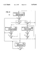
- FIG. 4 illustrates a state diagram of the present invention.
- FIG. 1 illustrates a personal digital assistant (PDA) incorporating a speaker telephone of the present invention.
- PDA personal digital assistant
- the speaker telephone includes a speaker 120, microphone 130, telephone line terminal 110 and earphone jack 140.
- the speaker telephone is ordinarily operated in the half-duplex mode. In the half-duplex mode, telephone transmission via the microphone 130 and telephone reception via the speaker 120 are both possible, but not simultaneously.
- telephone transmission refers to the act of transmitting an electrical representation of an audible input signal on a telephone line
- telephone reception refers to the act of producing audible output from electrical signals received from the telephone line.
- the speaker telephone Upon sensing a connection of an earphone at the earphone jack 140, the speaker telephone automatically transitions to the full-duplex mode of operation. In the full-duplex mode, telephone transmission via the microphone and reception via an earphone can occur simultaneously. Since the earphone output is relatively low volume and is physically isolated from the microphone, no significant feedback from earphone to microphone occurs, and howling is prevented. If the earphone is removed from the jack, the speaker telephone automatically reverts to half-duplex mode.
- FIG. 2 depicts a circuit diagram 200 representing one embodiment of the present invention.
- the circuit includes four primary components: a controller 250, a telephone line terminal 210 for receiving a telephone line, a microphone 230 and a speaker circuit 220.
- the controller 250 sets the operating state of the speaker telephone based on the previous operating state and the status of one or more of three controller inputs: a microphone input 251, a telephone line terminal input 252, and an earphone detector input 253.
- the earphone detector input 253 is coupled to an earphone detector 228, which indicates the connection or disconnection of an earphone.
- the microphone 230 and the telephone line terminal 210 are coupled to the controller 250 at the microphone input 251 and the telephone line terminal input 252, respectively.
- the controller 250 couples or decouples the microphone 230 and the telephone line terminal 210 to respectively enable or disable telephone transmission. Similarly, the controller 250 couples or decouples the telephone line terminal 210 and the speaker circuit 220 to enable or disable telephone reception.
- switches are used to perform the coupling/decoupling function. The type of switches used, which are controlled by controller 250, are well known to those skilled in the art.
- a switch 270 is closed or opened by the controller 250 to couple or decouple, respectively, the microphone 230 and the telephone line terminal 210.
- Another switch 275 is closed or opened by the controller to couple and decouple, respectively, the telephone line terminal 210 and the speaker circuit 220.
- the speaker circuit 220 includes an amplifier 222, a speaker 221, a switch 227, an earphone jack 240, volume control 223 and an earphone detector 228.
- the amplifier 222 produces an amplified output of signals received from the telephone line terminal 210. If no earphone is connected, the amplified output drives the speaker 221, producing audible output.
- a switch 227 is opened, decoupling the amplifier 222 from the speaker 221.
- the output of amplifier 222 is supplied to the earphone to produce audible output.
- a number of mechanisms may be employed to re-route the amplifier output from the speaker 221 to earphone jack 240 (and ultimately the earphone). For example, upon detecting insertion of an earphone plug into the earphone jack 240, electronic switching could be used to divert the output of the amplifier to from the speaker 221 to the earphone jack 240.
- the earphone detector 228 includes earphone detect switch 229 which is actuated by insertion of an earphone plug into the earphone jack 240, thereby indicating connection of the earphone. It will be appreciated that a variety of sensor mechanisms may be employed to detect insertion of an earphone plug.
- the earphone detector 228 is coupled to earphone detect input 253 of controller 250, providing the controller 250 with either a connect signal or a disconnect signal depending on whether the earphone plug is inserted into the earphone jack 240.
- the earphone detector 228 is also coupled to a volume control circuit 223 within the speaker circuit 220.
- the volume control circuit responsive to whether the earphone sensor indicates connection of an earphone, controls the amplification of electrical signals received from telephone line terminal 210 by amplifier 222. If an earphone connection is detected, the volume control circuit 223 attenuates the output of the amplifier 222 so as to prevent overdriving the earphone speaker.
- FIG. 3 illustrates a circuit diagram 300 representing an alternate embodiment of the present invention.
- Circuit diagram 300 includes similar primary elements as circuit diagram 200 (i.e., controller, microphone, speaker circuit 320 and telephone line terminal), but the switches 270 and 275 of circuit diagram 200 have been removed, and the coupling and decoupling function is performed instead by processor switching within the controller 350.
- Several components of the controller 350 are depicted in circuit diagram 300 to illustrate the manner in which processor switching occurs. These include analog-to-digital converters (ADCs) 365 and 366, digital-to-analog converters (DACs) 367 and 368, a processor 360 and a memory 362, all intercoupled by a bus 364.
- ADCs analog-to-digital converters
- DACs digital-to-analog converters
- the individual components may also reside outside the controller 350.
- the memory 362 is not itself part of the signal path which is coupled and decoupled by processor switching, the memory 362 may contain instructions and data used by the processor 360 to perform controller functions, including processor switching.
- a signal is received from the telephone line terminal 310, it is digitized by the ADC 366 and read by the processor 360 via the bus 364. If the speaker telephone is in an operating state wherein telephone reception is enabled, the processor 360 writes a version of the digitized signal to the DAC 368 which restores the signal to analog form. The output of the DAC 368 feeds speaker circuit 320 which produces audible output therefrom. Similarly, if a signal is received from the microphone 330, it is digitized by the ADC 365 and read by the processor 360 via the bus 364. If the speaker telephone is in an operating state wherein telephone transmission is enabled, the processor 360 writes a version of the digitized signal to the DAC 367 which restores the signal to analog form. The output of DAC 367 is coupled to the telephone line terminal 310, allowing transmission of the signal on the telephone line.
- the processor 360 may first process the signal (to filter noise, for example) so that the signal out-put by the processor 360 is not necessarily an exact reproduction of the signal received by the processor 360. It will further be appreciated that a number of permutations between the processor switching embodiment of FIG. 3 and the discrete switching embodiment of FIG. 2 are possible. For example, an embodiment might employ processor switching to couple and decouple the microphone 330 and the telephone line terminal 310, but a discrete switch (such as switch 275 of FIG. 2) to couple and decouple the telephone line terminal 310 and speaker circuit 320. Alternatively, an embodiment might employ a discrete switch (such as switch 270 of FIG. 2) to couple and decouple the microphone 330 and the telephone line terminal 310, but processor switching to couple and decouple the telephone line terminal 310 and speaker circuit 320. Furthermore, an embodiment might employ both discrete and processor switching to couple and &couple each signal path.
- FIG. 4 depicts an exemplary state diagram 400 of the operating states of the speaker telephone. These operating states are established by a controller (e.g., controller 250 of FIG. 2, or controller 350 of FIG. 3) in response to signals detected from the microphone, the telephone line terminal, and the earphone detector. While in the full-duplex operating state 440, the speaker telephone is in full-duplex mode. In each of the other operating states 410, 420, 430 depicted, the speaker telephone is in half-duplex mode.
- a controller e.g., controller 250 of FIG. 2, or controller 350 of FIG. 3
- the speaker telephone While in the full-duplex operating state 440, the speaker telephone is in full-duplex mode.
- the speaker telephone is in half-duplex mode.
- the telephone line terminal is decoupled from the microphone and the speaker circuit, and the controller repeatedly performs the steps of checking for an earphone connection or input (earphone detect) 412 from the microphone (microphone input 416 or telephone line terminal (telephone line terminal input) 414. If there is no earphone connection, the speaker telephone remains in the half-duplex detect state 410 until input from either the microphone or telephone line terminal is detected. If input from the telephone line terminal is detected 414, the speaker telephone transitions to the half-duplex receive state 420. If input from the microphone is detected 416, the speaker telephone transitions to the half-duplex transmit state 430. If an earphone is connected 412, the speaker telephone transitions to the full-duplex state 440.
- the telephone line terminal is coupled to the speaker circuit and decoupled from the microphone so that telephone reception via the speaker, but not telephone transmission via the microphone, is possible.
- the controller While in the half-duplex receive state 420, the controller repeatedly performs the steps of checking for an earphone connection 422 and checking for input from the telephone line terminal 424. If an earphone connection is detected 422, the speaker telephone transitions to the full-duplex operating state 440. If input from the telephone line terminal ceases 424, the speaker telephone transitions to the half-duplex detect state 410 discussed above.
- the telephone line terminal is coupled to the microphone and decoupled from the speaker circuit so that telephone transmission via the microphone, but not telephone reception via the speaker, is possible.
- the controller While in the half-duplex transmit state 430, the controller repeatedly performs the steps of checking for an earphone connection 432 and checking for input from the microphone 434. If an earphone connection is detected 432, the speaker telephone transitions to the full-duplex operating state 440. If input from the microphone ceases 434, the speaker telephone transitions to the half-duplex detect state 410 discussed above.
- the telephone line terminal is coupled to both the microphone and the speaker circuit, thereby enabling simultaneous telephone transmission via the microphone and reception via the earphone. If an earphone disconnection is detected 442, the speaker telephone transitions to the half-duplex detect state 410.
- the controller could perform the additional step of checking for input from the telephone line terminal and causing the speaker telephone to transition directly to the half-duplex receive state 420 (i.e., without first returning to the half-duplex detect state 410) upon detecting input from the telephone line terminal and cessation of input from the microphone.
- the speaker telephone could transition directly from the half-duplex receive state 420 to the half-duplex transmit state 430 upon detecting input from the microphone and cessation of input from the telephone line terminal.
- the controller when in the full-duplex state 440, the controller could perform the additional steps of checking for input from the microphone and telephone line terminal. The speaker telephone could then transition directly from the full-duplex state 440 to the half-duplex receive state 420 or the half-duplex transmit state 430 upon detecting earphone disconnection and either telephone line terminal input or microphone input, respectively.
- a controller may determine the status of inputs in a number of ways, including either periodically sampling the inputs (polling) or by responding to interrupts issued to a processor within the controller (interrupt processing).
- interrupt processing interrupt processing
- checking and “monitoring” are to be construed to encompass input status determination generally, including both input polling and interrupt processing.
- the controller may include a general purpose processor programmed with instructions that cause the processor to perform the recited steps, specific hardware components that contain hard-wired logic for performing the recited steps, or any combination of programmed general purpose computer components and custom hardware components.
- a general purpose processor programmed with instructions that cause the processor to perform the recited steps
- specific hardware components that contain hard-wired logic for performing the recited steps
- any combination of programmed general purpose computer components and custom hardware components any combination of programmed general purpose computer components and custom hardware components.
Abstract
Description
Claims (11)
Priority Applications (1)
| Application Number | Priority Date | Filing Date | Title |
|---|---|---|---|
| US08/643,507 US5675641A (en) | 1996-05-06 | 1996-05-06 | Dual-mode speaker telephone |
Applications Claiming Priority (1)
| Application Number | Priority Date | Filing Date | Title |
|---|---|---|---|
| US08/643,507 US5675641A (en) | 1996-05-06 | 1996-05-06 | Dual-mode speaker telephone |
Publications (1)
| Publication Number | Publication Date |
|---|---|
| US5675641A true US5675641A (en) | 1997-10-07 |
Family
ID=24581113
Family Applications (1)
| Application Number | Title | Priority Date | Filing Date |
|---|---|---|---|
| US08/643,507 Expired - Lifetime US5675641A (en) | 1996-05-06 | 1996-05-06 | Dual-mode speaker telephone |
Country Status (1)
| Country | Link |
|---|---|
| US (1) | US5675641A (en) |
Cited By (5)
| Publication number | Priority date | Publication date | Assignee | Title |
|---|---|---|---|---|
| US5959979A (en) * | 1997-05-05 | 1999-09-28 | Northrop Grumman Corporation | Half-duplex communication system for telemetry modems |
| US6925167B2 (en) * | 2001-02-01 | 2005-08-02 | Estech Systems, Inc. | Service observing in a voice over IP telephone system |
| US6981076B1 (en) * | 2000-09-27 | 2005-12-27 | Dell Products L.P. | Mechanism to disable dynamically a computer audio input/output connector |
| US7248864B1 (en) * | 2000-09-29 | 2007-07-24 | Palmsource, Inc. | System and method of managing incoming calls on a mobile device having an earplug |
| US20080247535A1 (en) * | 2007-04-09 | 2008-10-09 | Microsoft Corporation | Method and apparatus for mitigating impact of nonlinear effects on the quality of audio echo cancellation |
Citations (8)
| Publication number | Priority date | Publication date | Assignee | Title |
|---|---|---|---|---|
| US4912758A (en) * | 1988-10-26 | 1990-03-27 | International Business Machines Corporation | Full-duplex digital speakerphone |
| US5263083A (en) * | 1990-12-10 | 1993-11-16 | Rolm Company | Method and apparatus for sharing speakerphone processor among multiple users |
| US5349635A (en) * | 1992-11-19 | 1994-09-20 | At&T Bell Laboratories | Half-duplex or full-duplex automode operation for use in data communications equipment |
| US5396486A (en) * | 1992-12-17 | 1995-03-07 | At&T Corp. | Data communications equipment interface leads to signal half-duplex or full-duplex operation |
| US5448637A (en) * | 1992-10-20 | 1995-09-05 | Pan Communications, Inc. | Two-way communications earset |
| US5450618A (en) * | 1992-04-30 | 1995-09-12 | Motorola, Inc. | Full duplex and half duplex communication unit with volume setting |
| US5488657A (en) * | 1992-03-02 | 1996-01-30 | Acs Communications, Inc. | Apparatus for and method of operating an automatic log on/log off circuit in a telephone system by disconnecting a headset |
| US5504812A (en) * | 1994-10-11 | 1996-04-02 | Motorola, Inc. | Headset for use with a radiotelephone |
-
1996
- 1996-05-06 US US08/643,507 patent/US5675641A/en not_active Expired - Lifetime
Patent Citations (8)
| Publication number | Priority date | Publication date | Assignee | Title |
|---|---|---|---|---|
| US4912758A (en) * | 1988-10-26 | 1990-03-27 | International Business Machines Corporation | Full-duplex digital speakerphone |
| US5263083A (en) * | 1990-12-10 | 1993-11-16 | Rolm Company | Method and apparatus for sharing speakerphone processor among multiple users |
| US5488657A (en) * | 1992-03-02 | 1996-01-30 | Acs Communications, Inc. | Apparatus for and method of operating an automatic log on/log off circuit in a telephone system by disconnecting a headset |
| US5450618A (en) * | 1992-04-30 | 1995-09-12 | Motorola, Inc. | Full duplex and half duplex communication unit with volume setting |
| US5448637A (en) * | 1992-10-20 | 1995-09-05 | Pan Communications, Inc. | Two-way communications earset |
| US5349635A (en) * | 1992-11-19 | 1994-09-20 | At&T Bell Laboratories | Half-duplex or full-duplex automode operation for use in data communications equipment |
| US5396486A (en) * | 1992-12-17 | 1995-03-07 | At&T Corp. | Data communications equipment interface leads to signal half-duplex or full-duplex operation |
| US5504812A (en) * | 1994-10-11 | 1996-04-02 | Motorola, Inc. | Headset for use with a radiotelephone |
Cited By (6)
| Publication number | Priority date | Publication date | Assignee | Title |
|---|---|---|---|---|
| US5959979A (en) * | 1997-05-05 | 1999-09-28 | Northrop Grumman Corporation | Half-duplex communication system for telemetry modems |
| US6981076B1 (en) * | 2000-09-27 | 2005-12-27 | Dell Products L.P. | Mechanism to disable dynamically a computer audio input/output connector |
| US7248864B1 (en) * | 2000-09-29 | 2007-07-24 | Palmsource, Inc. | System and method of managing incoming calls on a mobile device having an earplug |
| US20070263827A1 (en) * | 2000-09-29 | 2007-11-15 | Palmsource, Inc. | System and method of receiving a call having an identified or unidentified number and an identified or unidentified name |
| US6925167B2 (en) * | 2001-02-01 | 2005-08-02 | Estech Systems, Inc. | Service observing in a voice over IP telephone system |
| US20080247535A1 (en) * | 2007-04-09 | 2008-10-09 | Microsoft Corporation | Method and apparatus for mitigating impact of nonlinear effects on the quality of audio echo cancellation |
Similar Documents
| Publication | Publication Date | Title |
|---|---|---|
| US10652662B2 (en) | Connectors for data transfer | |
| US10198386B2 (en) | Connectors for audio data transfer | |
| US7224992B2 (en) | Four pole stereo headset with push to talk capability in a duplex radio | |
| JPS59500442A (en) | Voice activated switch system | |
| WO1990003076A1 (en) | Method and apparatus for controlling transmission of voice and data signals | |
| WO2008140535A1 (en) | Audio interface device and method | |
| US5675641A (en) | Dual-mode speaker telephone | |
| EP0272068B1 (en) | Microphone circuit | |
| GB2174578A (en) | Loudspeaking telephone | |
| JPH0773387B2 (en) | Mobile phone device | |
| CN211378222U (en) | Audio circuit, head-mounted display equipment and head-mounted display system | |
| KR100454940B1 (en) | Apparatus for the connection between digital signal processor and main audio devices or ear microphone audio devices | |
| KR100827305B1 (en) | Mobile communication terminal and operating method for same | |
| US6009165A (en) | Full duplex speakerphone system | |
| CN100426901C (en) | Earphone and pushbutton detection device and method in mobile communication terminal | |
| JPS60200674A (en) | Peripheral telephone system | |
| KR200364672Y1 (en) | Earphone Jack Using Data Communication Possible Mobile Terminal | |
| US20070121804A1 (en) | Phone voice receiving /playing device | |
| WO2022168438A1 (en) | Communication system, speech input device, communication terminal, and program | |
| JP2659358B2 (en) | Hands-free phone | |
| KR200372368Y1 (en) | Coupler to extract talking a sound | |
| KR200315289Y1 (en) | USB based Voice Processing Device | |
| KR20010097228A (en) | Method and Device for sending and receving voice integrated function of headset and dialpad for sound device using USB port | |
| JPS6085664A (en) | Conference telephone set | |
| GB2276287A (en) | Electronic device with mode switching produced by applying switching signal to device output |
Legal Events
| Date | Code | Title | Description |
|---|---|---|---|
| AS | Assignment |
Owner name: SONY CORPORATION, JAPAN Free format text: ASSIGNMENT OF ASSIGNORS INTEREST;ASSIGNORS:WATANABE, KEN-ICHI;YOSHIDA, NORIFUMI;REEL/FRAME:007994/0645 Effective date: 19960417 Owner name: SONY ELECTRONICS, INC., NEW JERSEY Free format text: ASSIGNMENT OF ASSIGNORS INTEREST;ASSIGNORS:WATANABE, KEN-ICHI;YOSHIDA, NORIFUMI;REEL/FRAME:007994/0645 Effective date: 19960417 |
|
| AS | Assignment |
Owner name: SONY CORPORATION, JAPAN Free format text: CORRECTIV;ASSIGNORS:WATANABE, KEN-ICHI;YOSHIDA, NORIFUMI;REEL/FRAME:008500/0715 Effective date: 19960417 Owner name: SONY ELECTRONICS, INC., NEW JERSEY Free format text: CORRECTIV;ASSIGNORS:WATANABE, KEN-ICHI;YOSHIDA, NORIFUMI;REEL/FRAME:008500/0715 Effective date: 19960417 |
|
| STCF | Information on status: patent grant |
Free format text: PATENTED CASE |
|
| FEPP | Fee payment procedure |
Free format text: PAYOR NUMBER ASSIGNED (ORIGINAL EVENT CODE: ASPN); ENTITY STATUS OF PATENT OWNER: LARGE ENTITY |
|
| FPAY | Fee payment |
Year of fee payment: 4 |
|
| FPAY | Fee payment |
Year of fee payment: 8 |
|
| FPAY | Fee payment |
Year of fee payment: 12 |