US5660303A - Plastic case for photographic film cassette - Google Patents
Plastic case for photographic film cassette Download PDFInfo
- Publication number
- US5660303A US5660303A US08/324,983 US32498394A US5660303A US 5660303 A US5660303 A US 5660303A US 32498394 A US32498394 A US 32498394A US 5660303 A US5660303 A US 5660303A
- Authority
- US
- United States
- Prior art keywords
- lid
- case body
- case
- arcs
- photographic film
- Prior art date
- Legal status (The legal status is an assumption and is not a legal conclusion. Google has not performed a legal analysis and makes no representation as to the accuracy of the status listed.)
- Expired - Lifetime
Links
Images


Classifications
-
- G—PHYSICS
- G03—PHOTOGRAPHY; CINEMATOGRAPHY; ANALOGOUS TECHNIQUES USING WAVES OTHER THAN OPTICAL WAVES; ELECTROGRAPHY; HOLOGRAPHY
- G03C—PHOTOSENSITIVE MATERIALS FOR PHOTOGRAPHIC PURPOSES; PHOTOGRAPHIC PROCESSES, e.g. CINE, X-RAY, COLOUR, STEREO-PHOTOGRAPHIC PROCESSES; AUXILIARY PROCESSES IN PHOTOGRAPHY
- G03C3/00—Packages of films for inserting into cameras, e.g. roll-films, film-packs; Wrapping materials for light-sensitive plates, films or papers, e.g. materials characterised by the use of special dyes, printing inks, adhesives
Definitions
- the present invention relates to a plastic case for a photographic film cassette, especially for a photographic film cassette having a port portion protruding radially outward from the peripheral surface of a cylindrical cassette shell.
- a roll of photographic film is contained in a cassette shell made of a metal sheet.
- the ISO 135 photographic film cassette is encased in a plastic case made especially for keeping the photographic film cassette and, thereafter, packed in a rectangular box (e.g., a cardboard box) for sale.
- the conventional plastic case for the photographic film cassette is constituted of a case body having a closed bottom and a lid for tightly closing an open top of the case body.
- the case body and the lid are each formed from resins.
- the plastic case is intended to protect the photographic film from moisture, and is thus required to have a high moisture resistance or a low moisture permeability of not more than 5 to 10 mg/24 hours.
- the conventional photographic film cassette is substantially cylindrical except for a port portion forming a film passageway which protrudes slightly from the peripheral surface of the cassette shell, the conventional plastic case also has a fundamentally circular horizontal contour. Because tight-fitness of engagement between two plastic parts can be kept better in curves than straight portions, it has been relatively easy to tightly seal the conventional regular cylindrical plastic case by fitting the lid to the open top of the case body.
- photographic film cassettes are disclosed, for example, in Japanese Patent Application Nos. 5-127317 and 5-150402, whose cassette shell is constituted of elements made from resins, and which can wind the entire length of photographic film thereinto and advance the film leader to the outside by rotating the spool of the cassette.
- This type of photographic film cassette has a different contour from conventional ones, as is shown, for example, in FIG. 16. This is mainly because the new type photographic film cassette 110 needs to have an elongated port portion 110b for shielding the photographic film from ambient light entering through a film passageway 110a, and also enabling the film leader to be advanced to the outside through the film passageway 110a.
- Japanese Patent Application No. 3-176371 discloses rectangular and semi-cylindrical cases, for indicating the conditions of the photographic film encased therein, e.g., as to whether the photographic film has been exposed or not.
- Japanese Utility Model Publication No. 3-48581 discloses a case having an oblong horizontal contour so as to hold a couple of photographic film cassettes therein.
- JPY No. 3-48581 suggests forming ribs integrally with the lid.
- such ribs may cause the lid to have sink marks in the engaging portion with the case body. Therefore, it is hard to obtain sufficient moisture resistance.
- a primary object of the invention is to provide a plastic case for a photographic film cassette, which has a horizontal contour other than a regular circle, but has sufficiently reliable moisture barrier characteristics.
- Another object of the invention is to improve the plastic case with respect to space efficiency, smoothness in opening and closing the lid, efficiency and suitability in packing as well as in stacking, and also to lower the transportation cost.
- the present invention makes the case body have such a horizontal contour at least in its engaging portion with the lid, that is constituted of at least four arcs connected in series to one another, of which at least two arcs are different in radius from each other.
- the above inventive construction improves the plastic case with respect to tight-fitness and hence moisture resistance. Also the space efficiency is improved by minimizing unoccupied spaces in the case body, which contributes to lowering the transportation cost.
- adjacent arcs have different radiuses from each other, wherein radius ratio Rl/Rs of a longer radius Rl to a shorter radius Rs of adjacent two arcs is not more than 10. All of the arcs preferably have radii of not less than 3 mm. In either of these constructions, the arcs are smoothly connected to each other.
- the thickness of the rim of the lid is in a range from 0.5 mm to 2 mm.
- the resin material can be fulfilled in the molds without fail when forming the lid by injection molding. Therefore, undesirable coloring of the resin materials is prevented, which may be caused by heat energy generated during the compression in those portions which contact the air staying in the mold. Thus, the quality of the molded product is improved.
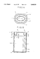
- FIG. 1A is a top plan view of a plastic case for a photographic film cassette, according to a preferred embodiment of the invention.
- FIG 1B is a vertical sectional view of the plastic case according to the embodiment shown in FIG. 1A, taken along line Y--Y of FIG. 1A;
- FIG. 2 is an explanatory view illustrating a horizontal contour of the case body of the plastic case according to the embodiment shown in FIGS. 1A and 1B;
- FIG. 3 is a horizontal sectional view of the case body, taken along line X--X of FIG. 1B, containing a photographic film cassette therein;
- FIG. 4 is a vertical sectional view illustrating essential parts for engagement between the case body and the lid of the plastic case according to the embodiment shown in FIG. 1B;
- FIG. 5 is an enlarged vertical sectional view of the plastic case shown in FIG. 4, taken along line Y--Y of FIG. 1A;
- FIG. 6 is a view similar to FIG. 5, but showing the engaging portion of the case wherein the lid has a flange for enabling the lid to be caught with the fingers;
- FIG. 7 is a sectional view of molds for forming the lid
- FIG. 8 is an explanatory view illustrating the flow of resin material in the molds shown in FIG. 7;
- FIG. 9 is a view similar to FIG. 5, but showing a modification of the engaging portions between the lid and the case body;
- FIG. 10 is a view similar to FIG. 5, but showing another modification of the engaging portions between the lid of the case body;
- FIG. 11 is a view similar to FIG. 5, but showing a further modification of the engaging portions between the lid and the case body;
- FIG. 12 is an explanatory view illustrating a horizontal contour of a case according to another embodiment of the invention.
- FIG. 13 is an explanatory view illustrating a stack of rectangular boxes for packing the plastic case according to the invention, in comparison with another stack of rectangular boxes for packing conventional plastic case;
- FIG. 14 is an explanatory view illustrating a horizontal contour of a photographic film cassette
- FIG. 15 is an explanatory view illustrating a horizontal contour of a case body of a plastic case according to an embodiment of the invention, for containing the photographic film cassette shown in FIG. 14;
- FIG. 16 is a horizontal sectional view of a case body of a conventional plastic case, containing the photographic film cassette shown in FIG. 3.
- a case 2 for a photographic film cassette 110 having a port portion 110b is constituted of a case body 3 and a lid 4.
- the case body 3 and the lid 4 are each formed from resin.
- the case body 3 is generally cylindrical and has a closed bottom and an open top for receiving the photographic film cassette 110 therein. The open top may be closed by the lid 4.
- FIGS. 2 and 3 schematically show a horizontal section of the case body 3 taken on line X--X of FIG. 1B.
- the horizontal contour of the case body 3 is constituted of a pair of arcs C1 with a radius R1 and another pair of arcs C2 with a larger radius R2 than the radius R1.
- the arcs C1 of one pair are continuous with the arcs C2 of the other pair to make an oval.
- the thickness of the side wall of the case body 3 is about 1 mm.
- FIG. 3 further shows the photographic film cassette 110 received in the case body 3. As shown in FIG. 3, unoccupied space is minimized as compared to a circular cross section case indicated by 12, and the photographic film cassette 110 is stably held in the plastic case 2 without being rotated therein.
- Rl and Rs represent a longer one and a shorter one of two different radii of two adjacent arcs in the irregular circle of the case body of the plastic case of the invention
- a groove 5 is formed in the annular inner peripheral surface of the case body 3 near the open top thereof, whereas the lid 4 has a projection 6 annularly formed in correspondence with the groove 5. Since the projection 6 is engaged in the groove 5, the lid 4 is tightly fitted in the case body 3.
- the depth of the groove 5 is 0.2 mm. Therefore, the diameters of the oval formed by the bottom of the annular groove 5 are 32.4 mm and 26.4 mm in the lengthwise and widthwise directions of the case body 3, respectively.
- the amount W may be other than 0.2 mm, but should be larger than zero, preferably from 0.02 mm to 0.4 mm, more preferably from 0.05 mm to 0.3 mm. If the amount W is designed to be less than 0.02 mm, the actual amount W may be less than zero in some places due to variation of tolerance in molding. If the amount W is designed to be more than 0.4 mm, it would be difficult to reliably form the lid 4 because the lid 4 would require a great deal of force to be removed from the mold and the lid 4 might be broken. With that large amount W, the lid 4 would also be hard to remove from the case body 3.
- the lid 4 has flanges 7 on the upper portion thereof which protrude about 0.5 mm to 2.5 mm radially outward from the outer periphery of the case body 3 when the lid 4 is fitted in the case body 3, so as to permit the fingers of a user to catch the lid 4 so as to facilitate removal of the lid 4 from the case body 3. It may be possible to form such flange around the circumference of the lid 4, but it is preferable to form the flanges 7 in the manner as shown in FIG. 1A. That is, crescent-shaped flanges 7 are formed between the top portions of the adjacent arcs C1 and C2.
- FIG. 5 shows an enlarged vertical section of the lid 4 and the case body 3 taken along a portion having no flange 7, as a comparison with FIG. 6.
- the lid 4 is formed with a recess 8 which is annular.
- the recess 8 facilitates elastic bending of the lid 4 which is required when fitting and removing the lid 4 into and out of the case body 3.
- the gap H there is provided a small gap H between the bottom of the lid 4 and the top of the photographic film cassette 110 encased in the plastic case 2, as is shown in FIG. 1B. It would be preferable to minimize the gap H in view of the space efficiency of the plastic case 2. However, if the gap H is designed to be less than 0.05 mm, the lid 4 cannot sometimes be fitted in the case body 3 because of variation of tolerance in forming and/or assembling the case. Accordingly, it is preferable to design the gap H to be not less than 0.05 mm.
- the photographic film cassette 110 In order to permit insertion of the photographic film cassette 110 into the plastic case 2, a certain gap or play is necessary between the outer periphery of the cassette 110 and the inner periphery of the case body 3. However, if the play is too large, the photographic film cassette 110 would be so unstable in the plastic case 2 that the cassette 110 would knock the plastic case 2 and may scratch the inner wall of the case. In a worst case, the photographic film cassette 110 or the plastic case 2 would be cracked. For this reason, it is preferable to minimize the play between the plastic case 2 and the cassette 110.
- the minimum play that is, the play between the tip of the port portion 110b and the inner wall of the case body 3 should preferably be from 0.1 mm to 2.0 mm.
- the diameter of the open top of the case body is also preferable to make the diameter of the open top of the case body larger than that of the bottom, or to form a plurality of ribs on the inner wall of the case, or to stuff any void with a buffer material such as sponge.
- the lid 4 is formed from plastic resin by injection molding.
- molds 21 for the lid 4 are constituted of upper and lower molds 21a and 21b.
- the resin is injected into the molds 21 through a gate 22 provided in a center of the molds 21, and spreads radially outward.
- the resin reaches the shorter ends 23 faster than the longer ends 24, so that the resin flows from the shorter end 23 toward the longer ends 24 along the circumference of the lid 4.
- the thickness T of the rim 4a of the lid 4 is not more than 2 mm, more preferably not more than 1.7 mm, and most preferably not more than 1.5 mm.
- the thickness T should preferably be not less than 0.5 mm, and more preferably not less than 0.8 mm.
- the engaging construction between the case body 3 and the lid 4 may be modified as shown in FIGS. 9, 10 or 11.
- at least an inward projection 32 is formed around the brim of the open top of a case body 31a, so that a projection 34a of a lid 33a passes over the projection 32 to secure the lid 33a to the case body 31a.
- the rim 35a of the lid 33a is disposed at the top, it is preferable to dimension the thickness T' of the rim 35a in a range from 0.5 mm to 2 mm, for reliable filling of resin in molding.
- a lid 33b has an annular flange which covers the rim of the open top of a case body 31b when the lid 33b is attached to the case body 31b.
- the lid 33b has a groove 36 formed around the inner periphery of the flange, while the case body 31b has a projection 34b formed around the outer periphery of the rim.
- a lid 33c is fitted on a case body 31c so as to cover the rim of the open top of the case body 31c with an annular flange of the lid 33c.
- the case body 31c has an outward projection 37 formed on the rim of the open top
- the lid 33c has a projection 34c formed around the inner periphery of the flange, which passes over the projection 37 of the case body 31c to secure the lid 33c to the case body 31c.
- the size of the oval formed by the top of the projection 36 or 37 should be slightly larger than the size of the oval horizontal contour at the bottom of the groove 36 or at the top of the projection 34c. Since the rims 35b and 35c of the lids 33b and 33c are disposed below the top surface of the lids 33b and 33c, it is unnecessary to definitely determine the thickness of the rims 35b and 35c.
- a case 40 for a photographic film cassette may have a horizontal contour constituted of eight arcs, of which four arcs 41a are drawn with a first radius and other four arcs 41b are drawn with a second radius, and the two kinds of arcs 41a and 41b are alternately connected to form a continuous curve. It is not always necessary to dispose those arcs which have the same radius in opposition to each other. It is also unnecessary to use an even number of arcs. However, using more than eight arcs complicates the shape of the molds required.
- the resin for forming the plastic case 2 according to the present invention should be a thermoplastic resin including olefin polymer such as polystyrene polyethylene, that is, high density polyethylene (HDPE), middle density polyethylene (MDPE), low density polyethylene (LDPE) or a mixture thereof, polypropylene (block copolymer, random copolymer, single polymer or a mixture thereof), and polyester resins such as polybutylene-terephthalate.
- olefin polymer such as polystyrene polyethylene, that is, high density polyethylene (HDPE), middle density polyethylene (MDPE), low density polyethylene (LDPE) or a mixture thereof, polypropylene (block copolymer, random copolymer, single polymer or a mixture thereof), and polyester resins such as polybutylene-terephthalate.
- a material of lower stiffness is preferable for obtaining a high moisture resistance and facilitating opening and closing of the lid 4.
- the resin for forming the case body 3 preferably has a modulus in flexure of not less than 3000 kg/cm 2 , more preferably not less than 6000 kg/cm 2 and most preferably not less than 8000 kg/cm 2 .
- the resin for forming the lid 4 preferably has a modulus in flexure of not less than 800 kg/cm 2 , more preferably not less than 1000 kg/cm 2 , and most preferably not less than 1200 kg/cm 2 .
- a preferable combination of the resin materials for the case body 3 and the lid 4 is polypropylene or high density polyethylene for the case body 3 and low density polyethylene for the lid 4.
- the fluidity of the resin for the case body 3 should be not less than 7 in MI (melt index) or MFR (melt flow rate), preferably not less than 10, and more preferably not less than 15.
- the MI or MFR of the resin for the lid 4 should be not less than 5, preferably not less than 8, and more preferably not less than 12.
- the resin for the case body 3 should not be less than 7 in MI or MFR, and the resin f or the lid 4 should not be less than 5 in MI or MFR. This is because the resin could not smoothly flow and hence a short shot may frequently occur during molding under those MI or MFR values.
- antioxidant is used for preventing oxidation of the resins that could be caused by a high temperature during the molding.
- Lubricants are used for improving the moldability and the smoothness for insertion of the photographic film cassette 110 into the plastic case 2 as well.
- Nucleating agent is used for promoting crystallization, shortening the molding cycle time, improving the stiffness or preventing deformation, and improving physical strength.
- Light screens or X-ray shielding materials are used for protecting the encased photographic film cassette 110 from ambient light or X-rays.
- the antioxidant includes free radical chain terminators which react on and inactivate free radicals (mainly ROO--) that act as chain transfer agents in oxidation, and peroxide decomposers which decompose and stabilize hydroperoxide (ROOH) which is the main generator of the free radicals.
- the former includes phenolic antioxidant and aromatic amine antioxidant.
- the later includes sulfuric antioxidant and phosphoric antioxidant. For these reasons, it is preferable to use phenolic antioxidant and phosphoric antioxidant in combination in the present invention.
- the preferable loading of the mixture of phenolic and phosphoric antioxidant is from 0.001 to 2.0 wt % (weight percent), more preferably from 0.01 to 0.5 wt %, and most preferably from 0.03 to 0.3 wt %.
- a loading of less than 0.001 wt % has little antioxidizing effect, but merely increase the mixing and milling cost.
- a loading of more than 2.0 wt % of antioxidant would yield undesirable affects such as fogging or disordering of sensitivity on the photographic film, because the photographic film utilizes oxidizing and reducing effects for photographic recording.
- lubricants which are loaded for improving the resin in moldability and increasing smoothness of the plastic case 2 on inserting the photographic film cassette 110
- saturated fatty acid amid lubricants such as behenic acid amid, stearic acid amid and palmitic acid amid
- unsaturated fatty acid amid lubricants such as erucamide and oleamide
- bis fatty acid amid lubricants such as methylene bisphenic amid, methylene bis-stearic acid amid, methylene bisoleic acid amid, ethylene bis-stearic acid amid, hexamethylene bis-stearic acid amid and hexamethylene bisoleic acid amid
- silicone lubricant such as dimethyl polysiloxane and its modification
- nonionic surface active agent lubricants such as liquid paraffin, natural paraffin, micro-wax, synthetic paraffin, polyethylene wax, polypropylene wax, chlorinated hydrocarbon and fluorocarbon
- fatty acid lubricants such as behenic acid amid, stearic acid
- a preferable loading of the lubricants is from 0.01 to 5.0 wt %. Loading of less than 0.01 wt % has little lubricating effect, but merely increases the mixing and milling cost. Loading of more than 5.0 wt % may cause bleed-out or slipping of screws, increases in the frequency of molding errors and lower milling quality, because the resin emission amount would fluctuate with too much lubricants.
- the loading is preferably from 0.01 to 3.0 wt %, and most preferably from 0.02 to 1.0 wt %, in the interest of prevention of molding error and bleed-out and so forth.
- hydrocarbon lubricants or metallic soaps which have less smoothing effects but contribute to improving upon dispersing quality of various admixtures and thus fluidity of the resin, it is possible to load them up to 20 wt % as long as no problems occur.
- a nucleating agent is added for speeding crystallizing and molding, improving stiffness, transparency, physical strength, and for preventing deformation.
- organic nucleating agents and inorganic nucleating agents are as follows:
- Organic nucleating agents are carboxylic acid, dicarboxylic acid, salts and anhydride of these materials, salts and ester of aromatic sulfonic acid, aromatic phosphinic acid, aromatic phosphonic acid, aromatic carbonic acid and aluminum salts thereof, metallic salts of aromatic phosphoric acid, alkyl alcohol of C8 to C30, condensate of polyhydroxy alcohol and aldehyde, as well as alkyl amine, and include, for example, p-t-butyl-benzoic acid aluminum, 1,3.2,4-dibenzyliden sorbitol, di-substituted-dibenzyliden sorbitol compound, metallic salts such as calcium or magnesium salt of stearyl lactic acid, N-(2-hydroxyethyl) -stearyl amine, metallic salts such as lithium salt, sodium salt, potassium salt, calcium salt or magnesium salt of 1.2-hydroxy stearic acid, alkyl alcohol such as stearyl alcohol and lauric alcohol, be
- Inorganic nucleating agents are alkali metal hydroxide such as lithium hydroxide, sodium hydroxide and potassium hydroxide, alkali metal oxide such as sodium oxide, alkali metal carbonate such as lithium carbonate, sodium carbonate, potassium carbonate, sodium bicarbonate and potassium bicarbonate, alkali earth metal hydroxide such as calcium hydroxide, magnesium hydroxide and barium hydroxide, and alkali earth metal oxide such as calcium carbonate and calcium oxide.
- Nucleating agents are not limited to the above examples, but other known nucleating agents may be applicable of course, two or more nucleating agents may be added to the resin. Loading of the nucleating agent is from 0.01 to 2.0 wt %, preferably from 0.05 to 11.0 wt %. Loading of less than 0.01 wt % has little effect. On the other hand, the nucleating effect would not increase beyond the loading of 2.0 wt %, but the cost would increase.
- a light screen agent which is used for protecting the photographic film cassette from ambient light
- These light screen agents may be used individually or in combination with each other, or in combination with dye.
- the above light screen agents may be subjected to some surface treatment.
- a preferable loading of the light screen is 0.01 to 30 wt %. Loading of less than 0.01 wt % would have almost no light shielding effect, but merely increase the milling cost.
- At least one of barium compound, zinc or zinc compound, tin or tin compound, and lead or lead compound is loaded in the resin material at 10 to 50 wt %.
- appearance and drop impact strength are lowered by the loading of such a material unless the plastic case 2 has a sufficient thickness.
- the above-described plastic case 2 for a photographic film cassette is required to have moisture resistance or moisture barrier characteristics of not more than 20 mg/24 hours, preferably not more than 15 mg/24 hours, more preferably not more than 10 mg/24 hours, and most preferably 5 mg/24 hours, although these values may be varied, depending on the kind of the photographic film to be encased therein.
- the weight of the plastic case 2 containing about 5 g of hygroscopic agent such as potassium chloride is measured before and after leaving the same for 24 hours under temperature of 40° C. and humidity of 90% RH.
- the plastic case according to the present invention is superior to the comparative samples in moisture resistance and space efficiency. Therefore, the transportation cost can be lowered.
- a rectangular box 45 for packing the plastic case 2 according to the invention may have a smaller internal volume than a rectangular box 44 for packing the conventional plastic case 120. Accordingly, the case according to the present invention is also superior to the conventional ones in the stability in stacking when the same number of these rectangular boxes are stacked on top of another.
- inventive plastic cases and rectangular boxes therefor were made to contain the same kind of photographic film cassette 50 as shown in FIG. 14.
- Both the inventive and comparative plastic cases were made to have a play of not less than 0.5 mm around the periphery of the photographic film cassette 50.
- the rectangular boxes were made to have a play of about 0.25 mm around the periphery of the related plastic case.
- the photographic film cassette 50 has a horizontal contour of an irregular shape which is mainly formed by an arc 51a of 4 mm radius, arcs 51b of 10.5 mm radius and straight portions 51c connecting these arcs to each other, and has a port portion 50a protruding 3.7 mm from the adjacent peripheral surface.
- the irregular shape is 30.29 mm by 21 mm in diameter. It is preferable to determine the radii of the two kinds of arcs 51a and 51b, which substantially determine the lengthwise and widthwise diameters of the photographic film cassette 50 within a range of ⁇ 20% around the above-mentioned values, respectively.
- the radiuses 51a and 51b differ more than 20% from the above-mentioned values, it will be difficult to make the photographic film cassette have a streamlined contour.
- FIG. 15 schematically illustrates a horizontal contour of a preferred embodiment of the plastic case 60 for containing the film cassette 50.
- the outer periphery of the plastic case 60 is formed by a pair of arcs 61a of 6.55 mm radius and a pair of arcs 61b of 18.75 mm radius, such that the two arcs of each pair are opposed to each other, and that the arcs 61a and 61b are connected to each other.
- the plastic case 60 is 34.1 mm by 5.08 mm in diameter, and the peripheral wall is about 1 mm thick. Consequently, the radius ratio Rl/Rs of the arc 61b to the arc 61a is 2.86.
- Table 2 shows the results of evaluation of external dimensions and internal volume of the two kinds of rectangular boxes for packing the inventive plastic case 60 and the comparative plastic case. Also the ratio of volume of the box for the plastic case 60 to that of the box for the comparative case is figured in Table 2.
- the internal volume of the rectangular box for the inventive plastic case 60 can be remarkably small in comparison with the rectangular box for he conventional plastic case having a regular circular horizontal contour. Therefore, the total size of the box can be smaller than a conventional box. Since the box for the plastic case 60 is smaller in height and larger in width compared to the conventional box, when stacked in a manner as shown in FIG. 13, the box for the plastic case 60 has improved stability in stacking, compared to the conventional box, such as the box 44.
Abstract
Description
              TABLE 1
______________________________________
                                 EMBODI-
              REGULAR   OBLONG   MENT OF THE
       SQUARE CIRCLE    CIRCLE   INVENTION
______________________________________
VOLUME   B(1)     N(0.67)   G(0.55)
                                   G(0.57)
STABILITY
         N        N         G
IN
STACKING
SUITABILITY
         N        G         N      N
FOR AUTO-
MATION
MOISTURE B        G         N or B G
RESISTANCE
TRANSPORT
         B(1)     N(0.67)   G(0.55)
                                   G(0.57)
COST
______________________________________
              TABLE 2
______________________________________
                      EMBODIMENT OF
          REGULAR CIRCLE
                      THE INVENTION
______________________________________
HEIGHT      33.89         26.08
WIDTH       33.89         35.10
LENGTH      49.00         49.00
VOLUME      56278         44855
VOLUME RATIO
             1.000         0.797
______________________________________
Claims (12)
Applications Claiming Priority (2)
| Application Number | Priority Date | Filing Date | Title |
|---|---|---|---|
| JP5-259780 | 1993-10-18 | ||
| JP25978093 | 1993-10-18 |
Publications (1)
| Publication Number | Publication Date |
|---|---|
| US5660303A true US5660303A (en) | 1997-08-26 |
Family
ID=17338878
Family Applications (1)
| Application Number | Title | Priority Date | Filing Date |
|---|---|---|---|
| US08/324,983 Expired - Lifetime US5660303A (en) | 1993-10-18 | 1994-10-18 | Plastic case for photographic film cassette |
Country Status (2)
| Country | Link |
|---|---|
| US (1) | US5660303A (en) |
| DE (1) | DE4437258A1 (en) |
Cited By (6)
| Publication number | Priority date | Publication date | Assignee | Title |
|---|---|---|---|---|
| US6544609B1 (en) | 2000-07-12 | 2003-04-08 | Alcoa Closure Systems International, Inc. | Stiff and impact resistant compositions containing poly(propylene) or poly(ethylene/propylene) and calcium carbonate for closures |
| US20040040965A1 (en) * | 2002-08-28 | 2004-03-04 | The Procter & Gamble Company | Containment vessel |
| US20040178165A1 (en) * | 2003-03-12 | 2004-09-16 | Konefal Robert S. | Closure and container package with child-resistant and non-child-resistant modes of operation |
| US20070119743A1 (en) * | 2005-02-23 | 2007-05-31 | The Glad Products Company | Container |
| US20080149514A1 (en) * | 2000-12-27 | 2008-06-26 | Hitachi Chemical Company, Ltd. | Method for packaging a photosensitive film roll, resin case therefor, method for recovering and reusing the case, and photosensitive film roll package and method for conveying the same |
| US20190092697A1 (en) * | 2017-09-25 | 2019-03-28 | Kabushiki Kaisha Toshiba | Container and method for closing an opening of container |
Families Citing this family (2)
| Publication number | Priority date | Publication date | Assignee | Title |
|---|---|---|---|---|
| DE29516418U1 (en) * | 1995-10-17 | 1995-12-07 | Honerkamp Johannes | Archiving system |
| DE19541560A1 (en) | 1995-11-08 | 1997-05-15 | Agfa Gevaert Ag | Packaging for photographic films |
Citations (21)
| Publication number | Priority date | Publication date | Assignee | Title |
|---|---|---|---|---|
| US4351447A (en) * | 1981-07-31 | 1982-09-28 | Graff Stewart M | Reusable resiliently distortable sheet plastic closure for application to rimmed containers |
| US4535889A (en) * | 1984-02-08 | 1985-08-20 | The Stouffer Corporation | Frozen food package and cover lid |
| US4560083A (en) * | 1984-01-16 | 1985-12-24 | Trw Inc. | Closure and method for an aperture |
| US4640435A (en) * | 1986-01-23 | 1987-02-03 | Sun Coast Plastics, Inc. | Plastic closure for beverage container |
| US4715496A (en) * | 1985-01-24 | 1987-12-29 | Bramlage Gesellschaft Mit Beschrankter Haftung | Shoe polish can |
| US4784285A (en) * | 1987-08-03 | 1988-11-15 | Chemcast Corporation | Dual durometer self locking and sealing plugs and method for making same |
| US4799602A (en) * | 1987-04-08 | 1989-01-24 | Metal Box P.L.C. | Plug lid for a container |
| US4844961A (en) * | 1986-10-30 | 1989-07-04 | Fuji Photo Film Co., Ltd. | Container for photographic film cartridge |
| US4930644A (en) * | 1988-12-22 | 1990-06-05 | Robbins Edward S Iii | Thin film container with removable lid and related process |
| US4960626A (en) * | 1986-06-11 | 1990-10-02 | Fuji Photo Film Co., Ltd. | Container for photographic film cartridge |
| US4969581A (en) * | 1989-08-08 | 1990-11-13 | The Procter & Gamble Company | Unequivocal bottom delivery container with self-sealing valve |
| JPH0348581A (en) * | 1989-04-25 | 1991-03-01 | Sony Corp | Video camera |
| JPH03176371A (en) * | 1989-11-29 | 1991-07-31 | Nikon Corp | Housing case for film patrone |
| US5069357A (en) * | 1990-07-16 | 1991-12-03 | Anderson Jack R | Panel for animal truck ventilation ports |
| US5106665A (en) * | 1989-02-16 | 1992-04-21 | Fuji Photo Film Co., Ltd. | Container for photographic film cartridge |
| US5139164A (en) * | 1991-11-14 | 1992-08-18 | Chesebrough-Pond's Usa Co., Division Of Conopco, Inc. | Oval container with interlocking nibs |
| JPH05127317A (en) * | 1991-04-30 | 1993-05-25 | Fuji Photo Film Co Ltd | Photographic film cartridge |
| JPH05150402A (en) * | 1991-11-28 | 1993-06-18 | Fuji Photo Film Co Ltd | Photographic film cartridge and camera |
| JPH0627593A (en) * | 1992-05-13 | 1994-02-04 | Fuji Photo Film Co Ltd | Container for photographic film cartridge |
| JPH06222512A (en) * | 1993-01-25 | 1994-08-12 | Konica Corp | Cartridge housing container |
| US5368178A (en) * | 1992-03-09 | 1994-11-29 | Towns; Edward J. | Container and closure therefore having conical sealing surfaces |
-
1994
- 1994-10-18 US US08/324,983 patent/US5660303A/en not_active Expired - Lifetime
- 1994-10-18 DE DE4437258A patent/DE4437258A1/en not_active Withdrawn
Patent Citations (21)
| Publication number | Priority date | Publication date | Assignee | Title |
|---|---|---|---|---|
| US4351447A (en) * | 1981-07-31 | 1982-09-28 | Graff Stewart M | Reusable resiliently distortable sheet plastic closure for application to rimmed containers |
| US4560083A (en) * | 1984-01-16 | 1985-12-24 | Trw Inc. | Closure and method for an aperture |
| US4535889A (en) * | 1984-02-08 | 1985-08-20 | The Stouffer Corporation | Frozen food package and cover lid |
| US4715496A (en) * | 1985-01-24 | 1987-12-29 | Bramlage Gesellschaft Mit Beschrankter Haftung | Shoe polish can |
| US4640435A (en) * | 1986-01-23 | 1987-02-03 | Sun Coast Plastics, Inc. | Plastic closure for beverage container |
| US4960626A (en) * | 1986-06-11 | 1990-10-02 | Fuji Photo Film Co., Ltd. | Container for photographic film cartridge |
| US4844961A (en) * | 1986-10-30 | 1989-07-04 | Fuji Photo Film Co., Ltd. | Container for photographic film cartridge |
| US4799602A (en) * | 1987-04-08 | 1989-01-24 | Metal Box P.L.C. | Plug lid for a container |
| US4784285A (en) * | 1987-08-03 | 1988-11-15 | Chemcast Corporation | Dual durometer self locking and sealing plugs and method for making same |
| US4930644A (en) * | 1988-12-22 | 1990-06-05 | Robbins Edward S Iii | Thin film container with removable lid and related process |
| US5106665A (en) * | 1989-02-16 | 1992-04-21 | Fuji Photo Film Co., Ltd. | Container for photographic film cartridge |
| JPH0348581A (en) * | 1989-04-25 | 1991-03-01 | Sony Corp | Video camera |
| US4969581A (en) * | 1989-08-08 | 1990-11-13 | The Procter & Gamble Company | Unequivocal bottom delivery container with self-sealing valve |
| JPH03176371A (en) * | 1989-11-29 | 1991-07-31 | Nikon Corp | Housing case for film patrone |
| US5069357A (en) * | 1990-07-16 | 1991-12-03 | Anderson Jack R | Panel for animal truck ventilation ports |
| JPH05127317A (en) * | 1991-04-30 | 1993-05-25 | Fuji Photo Film Co Ltd | Photographic film cartridge |
| US5139164A (en) * | 1991-11-14 | 1992-08-18 | Chesebrough-Pond's Usa Co., Division Of Conopco, Inc. | Oval container with interlocking nibs |
| JPH05150402A (en) * | 1991-11-28 | 1993-06-18 | Fuji Photo Film Co Ltd | Photographic film cartridge and camera |
| US5368178A (en) * | 1992-03-09 | 1994-11-29 | Towns; Edward J. | Container and closure therefore having conical sealing surfaces |
| JPH0627593A (en) * | 1992-05-13 | 1994-02-04 | Fuji Photo Film Co Ltd | Container for photographic film cartridge |
| JPH06222512A (en) * | 1993-01-25 | 1994-08-12 | Konica Corp | Cartridge housing container |
Cited By (9)
| Publication number | Priority date | Publication date | Assignee | Title |
|---|---|---|---|---|
| US6544609B1 (en) | 2000-07-12 | 2003-04-08 | Alcoa Closure Systems International, Inc. | Stiff and impact resistant compositions containing poly(propylene) or poly(ethylene/propylene) and calcium carbonate for closures |
| US20080149514A1 (en) * | 2000-12-27 | 2008-06-26 | Hitachi Chemical Company, Ltd. | Method for packaging a photosensitive film roll, resin case therefor, method for recovering and reusing the case, and photosensitive film roll package and method for conveying the same |
| US7597195B2 (en) * | 2000-12-27 | 2009-10-06 | Hitachi Chemical Company, Ltd. | Method for packaging a photosensitive film roll, resin case therefor, method for recovering and reusing the case, and photosensitive film roll package and method for conveying the same |
| US7677014B2 (en) | 2000-12-27 | 2010-03-16 | Hitachi Chemical Company, Ltd. | Method for packaging a photosensitive film roll, resin case therefor, method for recovering and reusing the case, and photosensitive film roll package and method for conveying the same |
| US20040040965A1 (en) * | 2002-08-28 | 2004-03-04 | The Procter & Gamble Company | Containment vessel |
| US6899246B2 (en) * | 2002-08-28 | 2005-05-31 | The Procter & Gamble Company | Containment vessel |
| US20040178165A1 (en) * | 2003-03-12 | 2004-09-16 | Konefal Robert S. | Closure and container package with child-resistant and non-child-resistant modes of operation |
| US20070119743A1 (en) * | 2005-02-23 | 2007-05-31 | The Glad Products Company | Container |
| US20190092697A1 (en) * | 2017-09-25 | 2019-03-28 | Kabushiki Kaisha Toshiba | Container and method for closing an opening of container |
Also Published As
| Publication number | Publication date |
|---|---|
| DE4437258A1 (en) | 1995-04-20 |
Similar Documents
| Publication | Publication Date | Title |
|---|---|---|
| US5660303A (en) | Plastic case for photographic film cassette | |
| US5106665A (en) | Container for photographic film cartridge | |
| US6619481B2 (en) | Article of manufacture and method for protecting information-storage devices | |
| JP3122274B2 (en) | Patrone storage container | |
| US5225466A (en) | Resin composition for articles molded by injection molding for photographic photosensitive materials | |
| US7341220B2 (en) | Roll support member and recording material package employing same | |
| JPH0761489A (en) | Tape cassette storage case | |
| US4512470A (en) | Storage case for a magnetic-tape cassette | |
| US5720389A (en) | Plastic case for photographic film cassette | |
| US20070175778A1 (en) | Cardboard packing box for cartridge container | |
| US20070175779A1 (en) | Cartridge container | |
| US4651876A (en) | Cassette protective cover | |
| US20070209952A1 (en) | Cartridge accommodation case | |
| JPH0481784B2 (en) | ||
| JP3327700B2 (en) | Photo film patrone container | |
| JP3108168B2 (en) | Light lock | |
| EP1813544A1 (en) | Cartridge container | |
| JPS6014237A (en) | Photosensitive material packaging material | |
| JPS627047A (en) | Holder for cassette of photographic film | |
| JP3598144B2 (en) | Photo film patrone container | |
| JP4207221B2 (en) | Roll support member and recording material package using the same | |
| JP2797156B2 (en) | Photo film container | |
| JP2007197074A (en) | Cartridge accommodating case | |
| JPH02221957A (en) | Main body of container for photographic film cartridge | |
| EP1431817B1 (en) | Roll support member and recording material package employing same |
Legal Events
| Date | Code | Title | Description |
|---|---|---|---|
| AS | Assignment |
Owner name: FUJI PHOTO FILM CO., LTD. NO. 210 NAKANUMA, MINAM Free format text: ASSIGNMENT OF ASSIGNORS INTEREST;ASSIGNOR:HIROSE, MASUHIKO;REEL/FRAME:007204/0866 Effective date: 19941007 |
|
| STCF | Information on status: patent grant |
Free format text: PATENTED CASE |
|
| FEPP | Fee payment procedure |
Free format text: PAYOR NUMBER ASSIGNED (ORIGINAL EVENT CODE: ASPN); ENTITY STATUS OF PATENT OWNER: LARGE ENTITY |
|
| FPAY | Fee payment |
Year of fee payment: 4 |
|
| FPAY | Fee payment |
Year of fee payment: 8 |
|
| AS | Assignment |
Owner name: FUJIFILM CORPORATION, JAPAN Free format text: ASSIGNMENT OF ASSIGNORS INTEREST;ASSIGNOR:FUJIFILM HOLDINGS CORPORATION (FORMERLY FUJI PHOTO FILM CO., LTD.);REEL/FRAME:018904/0001 Effective date: 20070130 Owner name: FUJIFILM CORPORATION,JAPAN Free format text: ASSIGNMENT OF ASSIGNORS INTEREST;ASSIGNOR:FUJIFILM HOLDINGS CORPORATION (FORMERLY FUJI PHOTO FILM CO., LTD.);REEL/FRAME:018904/0001 Effective date: 20070130 |
|
| FPAY | Fee payment |
Year of fee payment: 12 |