US5659380A - Bolt and engagement aperture lens joint structure for frameless spectacles - Google Patents
Bolt and engagement aperture lens joint structure for frameless spectacles Download PDFInfo
- Publication number
- US5659380A US5659380A US08/604,659 US60465996A US5659380A US 5659380 A US5659380 A US 5659380A US 60465996 A US60465996 A US 60465996A US 5659380 A US5659380 A US 5659380A
- Authority
- US
- United States
- Prior art keywords
- lens
- circular
- shank
- bolt
- joint section
- Prior art date
- Legal status (The legal status is an assumption and is not a legal conclusion. Google has not performed a legal analysis and makes no representation as to the accuracy of the status listed.)
- Expired - Fee Related
Links
Images


Classifications
-
- G—PHYSICS
- G02—OPTICS
- G02C—SPECTACLES; SUNGLASSES OR GOGGLES INSOFAR AS THEY HAVE THE SAME FEATURES AS SPECTACLES; CONTACT LENSES
- G02C1/00—Assemblies of lenses with bridges or browbars
- G02C1/02—Bridge or browbar secured to lenses without the use of rims
Definitions
- the present invention relates to a lens joint structure for frameless spectacles, particularly appropriate both for connecting a temple to each lens and for connecting a bridge to the lenses arranged side by side.
- FIGS. 16 and 17 A conventional lens joint structure for frameless spectacles, particularly a temple-to-lens joint for connecting a temple to the outer edge of each lens and a bridge-to-lens joint for connecting a bridge to the inner edge of each lens are shown in FIGS. 16 and 17.
- An abutting piece “b” is curved to fit on a selected part of the lens circumference "a”, and is soldered to a joint body "c". Also, the abutting piece “b” is soldered to a joint piece "e”, which has a through hole "d" at its end.
- the temple-to-lens joint or bridge-to-lens joint thus made by soldering is attached to the lens by applying the abutting piece "b" to the selected part of the lens circumference "a”; putting the through hole “d” of the joint piece “e” in alignment with an associated through hole “f” of the lens; and by inserting a bolt or screw “g” in these through holes to be tightened by driving the thread "h” of the screw "g” in an associated nut "i” on the other side of the lens.
- the conventional lens joint structure has a plurality of small pieces soldered, and therefore, a corresponding number of soldering steps are required in producing lens joints. This is a cause for lowering the productivity of frameless spectacles. Also, there is a fear that soldered parts of frameless spectacles are damaged or separated when the temples are inadvertently opened too wide.
- the joints are subjected to controlled bending, which, however, localizes stress strong enough to cause breaks or cracks in such localized parts of the lens.
- One object of the present invention is to provide an improved lens joint structure for frameless spectacles, which lens joint structure is guaranteed free of the defects described above in connection with the conventional lens joint structure.
- a lens joint structure for connecting the joint section of a temple or a bridge to an associated lens of frameless spectacles is improved in that a bolt is inserted in an engagement aperture of the joint section of the temple or bridge, and in an engagement aperture made in the temple-to-lens or bridge-to-lens jointing area of the lens to be tightened by an associated nut, the engagement apertures and the bolt having such a shape that relative rotation may be prevented between the joint section, the lens and the bolt.
- the engagement apertures may have a square or rectangular shape
- the bolt may have a head and a shank integrally connected to the head, at least the part of the shank extending in the engagement apertures of the joint section and lens having the same square or rectangular shape as these engagement apertures, and the remaining part of the shank having thread to engage with the nut on the side of the lens opposite to the side from which the bolt is inserted for fastening the joint section to the lens.
- a resin, square or rectangular hollow plug may be press-fitted in the square or rectangular engagement aperture of the lens, and then, the square or rectangular part of the shank of the bolt is inserted in the resin square or rectangular hollow plug from one side of the lens.
- the thread of the shank of the bolt appearing on the other side of the lens is threadedly engaged with, and tightened by the nut for fastening the joint section to the lens.
- the joint section may have a shank integrally connected thereto, at least the part of the shank extending in a square or rectangular engagement aperture made in the temple-to-lens or bridge-to-lens jointing area of the lens having the same square or rectangular shape as the engagement aperture of the lens, and the remaining part of the shank having thread to engage with an associated nut on the side of the lens opposite to the side from which the shank of the joint section is inserted for fastening the joint section to the lens.
- a resin square or rectangular hollow plug may be press-fitted in the square or rectangular engagement aperture of the lens.
- the square or rectangular part of the shank of the joint section is inserted in the resin square or rectangular hollow plug from one side of the lens, and the thread of the shank of the joint section appearing on the other side of the lens is threadedly engaged with the nut for fastening the joint section to the lens.
- the engagement aperture of the lens may be circular, and a resin circular hollow plug may be press-fitted in the circular engagement aperture of the lens.
- the engagement aperture of the joint section may be square or rectangular, and at least the part of the shank of a headed bolt extending in the square or rectangular engagement aperture of the joint section and the circular engagement aperture of the lens may have the same square or rectangular shape as the engagement aperture of the joint section, and the remaining part of the shank may have thread to engage with the nut on the side of the lens opposite to the side from which the bolt is inserted for fastening the joint section to the lens.
- the press-fitting of the square or rectangular part of the bolt into the circular plug causes the circular plug to be yieldingly deformed by allowing the corners of the square or rectangular shape of the shank of the bolt to invade the inner surface of the circular plug.
- the head of the bolt may have a transverse ridge extending thereacross or a pointing mark close to its circumference.
- an engagement aperture of the lens may be circular, and a soft resin circular hollow plug may be press-fitted in the circular engagement aperture of the lens.
- the joint section may have a shank integrally connected thereto, at least the part of the shank extending in the circular engagement aperture of the lens having a square or rectangular shape, and the remaining part of the shank having thread to engage with an associated nut.
- resin cylindrical plugs has the effect of: positively preventing the lens circumference from cracking; and integrating the square bolt to the lens via the intervening resin plug, which is deformed by allowing the corners of the square bolt to invade the inner circumference of the resin cylinder, accordingly increasing the friction between the outer circumference of the cylinder plug and the inner circumference of the engagement aperture of the lens.
- FIG. 1 shows, in section, a lens joint structure according to one embodiment of the present invention used as a temple-to-lens joint;
- FIG. 2 is a perspective view of same lens joint structure used as a bridge-to-lens joint
- FIG. 3 is a perspective view of same lens joint structure used as a temple-to-lens joint
- FIG. 4 is a perspective, exploded view of the lens joint structure
- FIG. 5 shows, in section, a lens joint structure according to another embodiment of the present invention used as a temple-to-lens joint
- FIG. 6 shows, in section, a lens joint structure according to still another embodiment of the present invention used as a temple-to-lens joint
- FIG. 7 is a perspective, exploded view of the lens joint structure of FIG. 6;
- FIG. 8 is a cross-section showing how the cylindrical plug is deformed by the square bolt in the lens joint structure of FIG. 6;
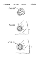
- FIG. 9 is a perspective view of a lens joint structure using a bolt whose head has a transverse ridge thereacross as an orientation pointer;
- FIG. 10 is a perspective view of a lens joint structure using a bolt whose head has an orientation mark
- FIG. 11 shows, in section, a lens joint structure according to still another embodiment of the present invention used as a temple-to-lens joint
- FIG. 12 is a perspective view of a polygonal bolt and a polygonal engagement aperture made in the temple-to-lens or bridge-to-lens jointing area of the lens;
- FIG. 13 is a perspective view of a resin polygonal plug to be press-fitted in the polygonal engagement aperture of FIG. 12;
- FIG. 14 is a cross-section showing how the cylindrical plug is deformed by the polygonal bolt when press-fitted therein;
- FIG. 15 is a cross-section showing how the cylindrical plug is deformed by the oval bolt when press-fitted therein;
- FIG. 16 shows conventional temple-to-lens and bridge-to-lens joint structures
- FIG. 17 shows, in section, how a temple is fixed to a lens by the conventional temple-to-lens joint structure.
- a lens joint structure according to a first embodiment of the present invention can be used as a temple-to-lens joint (FIG. 3) or a bridge-to-lens joint (FIG. 2) by connecting the joint section 2 of a temple 3 to a lens 6 by a square bolt 5 (FIG. 3) or by connecting the joint section 2 of a bridge 1 to a lens 6 by a square bolt 5 (FIG. 2).
- the lens joint structure according to the first embodiment is described below as being used as a temple-to-lens joint.
- the lens 6 has a square engagement aperture 7 made in its temple-to-lens jointing area.
- a resin square plug 9 is press-fitted in the square engagement aperture 7 of the lens 6 to provide a square hole 10.
- the joint section 2 has a square aperture aligned with the square hole 10 of the square plug 9.
- the bolt 5 comprises a head 12 and a shank integrally connected thereto, and the shank has a square part 4 and male-threaded part 13.
- the square bolt 5 is inserted from one side of the lens 6 in the square aperture 11 of the joint section 2 of the temple 3 and the square aperture 10 of the square plug 9, and the male-threaded part 13 of the bolt 5 appearing on the other side is threadedly engaged with an associated nut 16 via a washer 15.
- the bolt 5 is tightened by rotating the nut 16 about it, the joint section 2 can be connected to the lens 6 without permitting the joint section 2 from rotating relative to the lens 6.
- the joint section 2 of the temple 3 may have a square-and-thread shank 4 and 13 integrally connected to its inside end, as seen from FIG. 5.
- the square part 4 of the square-and-thread shank is inserted in the square hole 10 of the square plug 9 from one side of the lens 6, and the thread part 13 of the square-and-thread shank appearing from the other side of the lens 6 is threadedly engaged with the nut 16 to be tightened by rotating it about the thread part 13.
- the square-and-thread shank can be integrally connected to the inside end of the joint section 2 of the temple 3 by: forming the joint section 2 and the shank as a whole; soldering the square part 4 of the shank to the joint section 2; or press-fitting the square part 4 of the shank to a recess or aperture made in the joint section 2.
- the square part of the shank may be inserted directly in the engagement hole of the lens without the square plug intervening between the shank and the lens.
- a circular engagement hole 7 is made in the temple-to-lens jointing area of the lens 6, and a circular cylinder plug 17 of a soft synthetic resin such as nylon is press-fitted in the circular engagement hole 7.
- a square hole 11 is made in the end of the joint section 2 so as to be in alignment with the circular hole 19 of the cylindrical plug 17, which is fitted in the circular engagement hole 7 of the lens 6.
- a headed bolt 5 has a square part 4 integrally connected to its head 12 and a thread part 13 integrally connected to the square part 4, as shown in FIG. 7. The bolt 5 is inserted in the square hole 11 and the circular hole 19 from one side of the lens 6. The square part 4 of the bolt 5 is closely fitted in the square hole 11 of the joint section 2.
- the corners 20 of the square part 4 pushes the surrounding cylindrical wall until it is yieldingly withdrawn, thereby allowing the corners 20 of the square part 4 to invade the cylindrical plug 17, as shown in FIG. 8.
- the thread part 13 of the bolt 5 appearing on the other side of the lens 6 is threadedly engaged with the nut 16 via the washer 15.
- the joint section 2 can be connected to the lens 6, preventing the joint section 2 from rotating relative to the lens 6 by the square-to-square engagement at the bolt-to-joint section connecting area, and by square-to-circular engagement at the bolt-to-lens connecting area, which square-to-circular engagement is caused by the friction between the plug 17 and the lens 6.
- Such friction is increased to the extremity by forcedly invading the square part 4 of the bolt 5 into the surrounding circular thickness of plug 17.
- a square bolt which is to be inserted into a circular hole such as shown at 19 may be have a transverse ridge 25 across its head 12 (FIG. 9) or a pointing mark 26 close to the head circumference.
- the correct orientation of the temple 3 relative to the lens 6 is assured by inserting the bolt 5 with its transverse ridge 25 put vertical or with its pointing mark 26 put down.
- a joint section 2 may have a square-and-thread shank 4 and 13 integrally connected to its inside end, and the square part 4 of the square-and-thread shank is inserted in the circular hole 19 from one side of the lens 6.
- the square part 4 of the shank invades the surrounding circular thickness of the plug 17.
- the thread part 13 of the shank appearing on the other side of the lens 6 is threadedly engaged with the nut 16 via the washer.
- the square-and-thread shank may be integrally connected to the inside end of the joint section 2 by forming the joint section 2 and the shank as a whole, soldering the square part 4 of the shank to the joint section 2 or press-fitting the square part 4 of the shank to a recess or aperture made in the joint section 2.
- the engagement aperture which is made in the temple-to-lens jointing area or the bridge-to-lens jointing area of the lens may be triangular, hexagonal, or stellar. Then, the bolt must have a corresponding shape in cross section. In case that a fastening bolt or the shank of a joint section is inserted in the cylindrical plug which is press-fitted in the circular engagement aperture of the lens, the bolt or the shank of the joint section may have triangular, hexagonal, or stellar shape in cross section.
- FIG. 12 shows a stellar bolt 5 and a stellar engagement aperture 7 in the lens 6.
- FIG. 13 shows a stellar plug 9 to be fitted in the stellar engagement aperture 7 in the lens 6.
- FIG. 14 shows how the cylindrical plug 17 in the circular engagement aperture 7 is deformed by the stellar bolt 4 when press-fitted into the cylindrical plug 17.
- FIG. 15 shows how the cylindrical plug 17 in the circular engagement aperture 7 is deformed by an oval bolt 4a when press-fitted into the cylindrical plug 17.
Landscapes
- Physics & Mathematics (AREA)
- Health & Medical Sciences (AREA)
- General Physics & Mathematics (AREA)
- Ophthalmology & Optometry (AREA)
- Optics & Photonics (AREA)
- Eyeglasses (AREA)
Abstract
Description
Claims (9)
Priority Applications (3)
| Application Number | Priority Date | Filing Date | Title |
|---|---|---|---|
| EP94108446A EP0661575A1 (en) | 1993-12-29 | 1994-06-01 | Lens joint structures for frameless spectacles |
| JP16283794A JP3159604B2 (en) | 1993-12-29 | 1994-06-20 | Lens connection structure for frameless glasses |
| US08/604,659 US5659380A (en) | 1993-12-29 | 1996-02-21 | Bolt and engagement aperture lens joint structure for frameless spectacles |
Applications Claiming Priority (2)
| Application Number | Priority Date | Filing Date | Title |
|---|---|---|---|
| JP34997693 | 1993-12-29 | ||
| US08/604,659 US5659380A (en) | 1993-12-29 | 1996-02-21 | Bolt and engagement aperture lens joint structure for frameless spectacles |
Publications (1)
| Publication Number | Publication Date |
|---|---|
| US5659380A true US5659380A (en) | 1997-08-19 |
Family
ID=26579079
Family Applications (1)
| Application Number | Title | Priority Date | Filing Date |
|---|---|---|---|
| US08/604,659 Expired - Fee Related US5659380A (en) | 1993-12-29 | 1996-02-21 | Bolt and engagement aperture lens joint structure for frameless spectacles |
Country Status (2)
| Country | Link |
|---|---|
| US (1) | US5659380A (en) |
| EP (1) | EP0661575A1 (en) |
Cited By (22)
| Publication number | Priority date | Publication date | Assignee | Title |
|---|---|---|---|---|
| DE29901347U1 (en) * | 1999-01-27 | 1999-12-23 | Dr. Eugen Beck GmbH & Co, 59302 Oelde | Drill glasses frame |
| US6007200A (en) * | 1999-03-08 | 1999-12-28 | Aoyama Gankyo Kabushiki Kaisha | Lens holding mechanism of rimless spectacles |
| US6249504B1 (en) * | 1997-04-25 | 2001-06-19 | Alps Electric Co., Ltd. | Anti-vibration mechanism and disk drive device using the same |
| US6315409B1 (en) * | 2000-08-11 | 2001-11-13 | Fur Seal Company Limited | Fixtures and fitting structure for eyeglass lens |
| US6502940B1 (en) | 2001-12-11 | 2003-01-07 | The Hilsinger Company L.P. | Connection mounting for rimless eyewear lenses |
| US6655801B2 (en) * | 2001-12-27 | 2003-12-02 | Arts Optical Manufactory Ltd. | Locking apparatus with spectacle structure |
| US20040173420A1 (en) * | 2001-09-18 | 2004-09-09 | Knorr-Bremse Systeme Fuer Nutzfahrzeuge Gmbh | Disk brake, in particular, for a utility vehicle |
| US20040183995A1 (en) * | 2002-06-13 | 2004-09-23 | Helmut Haverkamp | Spectacles, particularly rimless drilled-lens spectables |
| WO2005083496A1 (en) * | 2004-02-26 | 2005-09-09 | Colin Hynes | Spectacle pins having pin-to-lens rotation-preventing design and temple hinge features |
| US20060268156A1 (en) * | 2005-05-31 | 2006-11-30 | Charles Gale | Stabilizer platform for a camcorder |
| US20060275101A1 (en) * | 2002-12-05 | 2006-12-07 | Zvi Feldman | Eyeglass assembly and fastening arrangement for assembly thereof |
| GB2411434B (en) * | 2004-02-26 | 2007-01-17 | Colin Hynes | Spectacles |
| US20080169737A1 (en) * | 2007-01-16 | 2008-07-17 | Min-Dy Shen | Adjustable Pull-Out Frame Structure |
| EP2093604A1 (en) * | 2008-02-20 | 2009-08-26 | Silcon Plastic S.R.L. | Device for fixing the lens to a frame of eyeglasses, particularly for three-part frames |
| EP2169446A1 (en) * | 2008-09-24 | 2010-03-31 | Leung Yuet-Charn | Connecting device for a rimless spectacle |
| US20100110367A1 (en) * | 2007-03-01 | 2010-05-06 | Isaac Karpel | Screwless mounting for eyeglasses |
| US8157372B1 (en) | 2011-04-12 | 2012-04-17 | Yuet-Charn Leung | Lens connection device for an eyewear |
| US20150054369A1 (en) * | 2013-08-21 | 2015-02-26 | Overly Hautz Motor Base Company | Motor mounting assembly and method of manufacture |
| BE1025634B1 (en) * | 2017-08-28 | 2019-05-13 | Netoptic Sa | Fastening of tenon and bridge of a telescope on glasses |
| US10465836B2 (en) | 2013-08-21 | 2019-11-05 | The Overly Hautz Motor Base Company | Motor mounting assembly and method of manufacture |
| US10975838B2 (en) * | 2015-12-14 | 2021-04-13 | Vestas Wind Systems A/S | Joint for connecting a wind turbine rotor blade to a rotor hub and associated method |
| US11852897B2 (en) | 2018-10-10 | 2023-12-26 | Michael Toulch | Eyeglasses and assembly including a component mounted to a lens |
Families Citing this family (5)
| Publication number | Priority date | Publication date | Assignee | Title |
|---|---|---|---|---|
| IT1281251B1 (en) * | 1995-12-06 | 1998-02-17 | Armando Rattaro | FIXING DEVICE FOR BRIDGE AND ARMS TO LENSES OF FRAMELESS GLASSES. |
| JPH10111481A (en) * | 1996-10-08 | 1998-04-28 | Mitsuo Kobayashi | Connecting structure of spectacle parts |
| DE19732667C2 (en) * | 1997-07-29 | 1999-08-19 | Geyer | Eyeglass holder |
| DK1127289T3 (en) * | 1998-11-04 | 2005-10-31 | Microvision Optical Inc | Uncovered glasses |
| ITBL20130012A1 (en) * | 2013-07-08 | 2015-01-09 | A V Ottica S N C Di Arcadio Vigna To & C | "METHOD OF TRAINING FROM LAMIERA, WITH APPLICATION TO LENSES, OF THE BRIDGE AND MUSETS OF THREE-PIECE GLASSES" |
Citations (2)
| Publication number | Priority date | Publication date | Assignee | Title |
|---|---|---|---|---|
| US4502765A (en) * | 1982-05-13 | 1985-03-05 | Cooper George F | Lens support system |
| US5412440A (en) * | 1992-12-08 | 1995-05-02 | Kabushiki Kaisha Takeda | Rimless spectacles with adjustable temples and lenses |
Family Cites Families (4)
| Publication number | Priority date | Publication date | Assignee | Title |
|---|---|---|---|---|
| FR557605A (en) * | 1922-10-19 | 1923-08-11 | Stevens And Company | Lens mounting system for nose clips, glasses, etc. |
| US2180820A (en) * | 1938-05-17 | 1939-11-21 | Gaspari & Co Inc J | Ophthalmic mounting |
| US2175355A (en) * | 1938-09-10 | 1939-10-10 | Bert J Lowres | Lens strap structure |
| FR1288875A (en) * | 1961-02-15 | 1962-03-30 | Improvements to the assembly of lenses or rings on spectacle frames |
-
1994
- 1994-06-01 EP EP94108446A patent/EP0661575A1/en not_active Withdrawn
-
1996
- 1996-02-21 US US08/604,659 patent/US5659380A/en not_active Expired - Fee Related
Patent Citations (2)
| Publication number | Priority date | Publication date | Assignee | Title |
|---|---|---|---|---|
| US4502765A (en) * | 1982-05-13 | 1985-03-05 | Cooper George F | Lens support system |
| US5412440A (en) * | 1992-12-08 | 1995-05-02 | Kabushiki Kaisha Takeda | Rimless spectacles with adjustable temples and lenses |
Cited By (27)
| Publication number | Priority date | Publication date | Assignee | Title |
|---|---|---|---|---|
| US6249504B1 (en) * | 1997-04-25 | 2001-06-19 | Alps Electric Co., Ltd. | Anti-vibration mechanism and disk drive device using the same |
| DE29901347U1 (en) * | 1999-01-27 | 1999-12-23 | Dr. Eugen Beck GmbH & Co, 59302 Oelde | Drill glasses frame |
| US6007200A (en) * | 1999-03-08 | 1999-12-28 | Aoyama Gankyo Kabushiki Kaisha | Lens holding mechanism of rimless spectacles |
| US6315409B1 (en) * | 2000-08-11 | 2001-11-13 | Fur Seal Company Limited | Fixtures and fitting structure for eyeglass lens |
| US6991073B2 (en) * | 2001-09-18 | 2006-01-31 | Knorr-Bremse Systeme Fuer Nutzfahrzeuge Gmbh | Disk brake, in particular, for a utility vehicle |
| US20040173420A1 (en) * | 2001-09-18 | 2004-09-09 | Knorr-Bremse Systeme Fuer Nutzfahrzeuge Gmbh | Disk brake, in particular, for a utility vehicle |
| US6502940B1 (en) | 2001-12-11 | 2003-01-07 | The Hilsinger Company L.P. | Connection mounting for rimless eyewear lenses |
| WO2003049526A2 (en) * | 2001-12-11 | 2003-06-19 | The Hilsinger Company, L.P. | Connection mounting for rimless eyewear lenses |
| WO2003049526A3 (en) * | 2001-12-11 | 2003-11-20 | Hilsinger Company L P | Connection mounting for rimless eyewear lenses |
| US6655801B2 (en) * | 2001-12-27 | 2003-12-02 | Arts Optical Manufactory Ltd. | Locking apparatus with spectacle structure |
| US7040752B2 (en) | 2002-06-13 | 2006-05-09 | Dr. Eugen Beck Gmbh & Co. | Spectacles, particularly rimless drilled-lens spectables |
| US20040183995A1 (en) * | 2002-06-13 | 2004-09-23 | Helmut Haverkamp | Spectacles, particularly rimless drilled-lens spectables |
| US20060275101A1 (en) * | 2002-12-05 | 2006-12-07 | Zvi Feldman | Eyeglass assembly and fastening arrangement for assembly thereof |
| WO2005083496A1 (en) * | 2004-02-26 | 2005-09-09 | Colin Hynes | Spectacle pins having pin-to-lens rotation-preventing design and temple hinge features |
| GB2411434B (en) * | 2004-02-26 | 2007-01-17 | Colin Hynes | Spectacles |
| US20060268156A1 (en) * | 2005-05-31 | 2006-11-30 | Charles Gale | Stabilizer platform for a camcorder |
| US20080169737A1 (en) * | 2007-01-16 | 2008-07-17 | Min-Dy Shen | Adjustable Pull-Out Frame Structure |
| US20100110367A1 (en) * | 2007-03-01 | 2010-05-06 | Isaac Karpel | Screwless mounting for eyeglasses |
| EP2093604A1 (en) * | 2008-02-20 | 2009-08-26 | Silcon Plastic S.R.L. | Device for fixing the lens to a frame of eyeglasses, particularly for three-part frames |
| EP2169446A1 (en) * | 2008-09-24 | 2010-03-31 | Leung Yuet-Charn | Connecting device for a rimless spectacle |
| US8157372B1 (en) | 2011-04-12 | 2012-04-17 | Yuet-Charn Leung | Lens connection device for an eyewear |
| US20150054369A1 (en) * | 2013-08-21 | 2015-02-26 | Overly Hautz Motor Base Company | Motor mounting assembly and method of manufacture |
| US9973056B2 (en) * | 2013-08-21 | 2018-05-15 | The Overly Hautz Motor Base Company | Motor mounting assembly and method of manufacture |
| US10465836B2 (en) | 2013-08-21 | 2019-11-05 | The Overly Hautz Motor Base Company | Motor mounting assembly and method of manufacture |
| US10975838B2 (en) * | 2015-12-14 | 2021-04-13 | Vestas Wind Systems A/S | Joint for connecting a wind turbine rotor blade to a rotor hub and associated method |
| BE1025634B1 (en) * | 2017-08-28 | 2019-05-13 | Netoptic Sa | Fastening of tenon and bridge of a telescope on glasses |
| US11852897B2 (en) | 2018-10-10 | 2023-12-26 | Michael Toulch | Eyeglasses and assembly including a component mounted to a lens |
Also Published As
| Publication number | Publication date |
|---|---|
| EP0661575A1 (en) | 1995-07-05 |
Similar Documents
| Publication | Publication Date | Title |
|---|---|---|
| US5659380A (en) | Bolt and engagement aperture lens joint structure for frameless spectacles | |
| EP0666490B1 (en) | Lens joint structure for frameless spectacles | |
| JPH0326493Y2 (en) | ||
| US5508758A (en) | Self-locking nut with threaded and self-locking members, useful for eye glasses, and a nut tightener and a nut supplier for same | |
| EP1260851A2 (en) | A lens connecting device and a method of connecting | |
| US5805259A (en) | Rimless eyeglasses having adjustable legs | |
| JPH0664263B2 (en) | Eyeglass frame | |
| US6808261B1 (en) | Rimless eyewear system and method | |
| US6315409B1 (en) | Fixtures and fitting structure for eyeglass lens | |
| KR100289336B1 (en) | Glasses Lens Connection Structure in Frameless Glasses | |
| WO2003049526A2 (en) | Connection mounting for rimless eyewear lenses | |
| US5988810A (en) | Support for spectacle glasses | |
| JP3051605U (en) | Glasses screwed structure | |
| JP3053251U (en) | Glasses nut | |
| JPH0637383Y2 (en) | Fixing structure for eyeglass frame parts | |
| JP3009982B2 (en) | Lock nut | |
| JP3012043U (en) | Fixing structure for eyeglass screws and lenses | |
| KR200231370Y1 (en) | A screw for fixing a glasses without a rim | |
| JPH032890Y2 (en) | ||
| JP2001193722A (en) | Male screw | |
| JP2587411Y2 (en) | Frame connection structure | |
| KR200246903Y1 (en) | holding structure of connection bar for rimless glasses | |
| JP3793079B2 (en) | Lens support structure for edgeless glasses | |
| JP2819373B2 (en) | Lock nut for eyeglasses | |
| KR200246391Y1 (en) | a spectacles be maded by a bended wire |
Legal Events
| Date | Code | Title | Description |
|---|---|---|---|
| FEPP | Fee payment procedure |
Free format text: PAYOR NUMBER ASSIGNED (ORIGINAL EVENT CODE: ASPN); ENTITY STATUS OF PATENT OWNER: LARGE ENTITY |
|
| AS | Assignment |
Owner name: YUGEN KAISHA MANA, JAPAN Free format text: ASSIGNMENT OF ASSIGNORS INTEREST;ASSIGNOR:KOBAYASHI, MITSUO;REEL/FRAME:009138/0330 Effective date: 19980414 |
|
| AS | Assignment |
Owner name: YUGEN KAISHA MENA JAPAN, JAPAN Free format text: CORRECTIVE ASSIGNMENT TO CORRECT ASSIGNEE'S NAME, PREVIOUSLY RECORDED AT REEL 9138, FRAME 0330;ASSIGNOR:KOBAYASHI, MITSUO;REEL/FRAME:009328/0745 Effective date: 19980414 |
|
| AS | Assignment |
Owner name: KABUSHIKI KAISHA KOBAYASHI, JAPAN Free format text: ASSIGNMENT OF ASSIGNORS INTEREST;ASSIGNOR:YUGEN KAISHA MONA JAPAN;REEL/FRAME:010731/0672 Effective date: 20000403 |
|
| FPAY | Fee payment |
Year of fee payment: 4 |
|
| REMI | Maintenance fee reminder mailed | ||
| AS | Assignment |
Owner name: CHARMANT INC., JAPAN Free format text: ASSIGNMENT OF ASSIGNORS INTEREST;ASSIGNOR:KOBAYASHI, KABUSHIKI KAISHA;REEL/FRAME:012435/0108 Effective date: 20010822 |
|
| FEPP | Fee payment procedure |
Free format text: PAT HOLDER NO LONGER CLAIMS SMALL ENTITY STATUS, ENTITY STATUS SET TO UNDISCOUNTED (ORIGINAL EVENT CODE: STOL); ENTITY STATUS OF PATENT OWNER: LARGE ENTITY |
|
| REFU | Refund |
Free format text: REFUND - PAYMENT OF MAINTENANCE FEE, 8TH YR, SMALL ENTITY (ORIGINAL EVENT CODE: R2552); ENTITY STATUS OF PATENT OWNER: LARGE ENTITY |
|
| FPAY | Fee payment |
Year of fee payment: 8 |
|
| REMI | Maintenance fee reminder mailed | ||
| LAPS | Lapse for failure to pay maintenance fees | ||
| STCH | Information on status: patent discontinuation |
Free format text: PATENT EXPIRED DUE TO NONPAYMENT OF MAINTENANCE FEES UNDER 37 CFR 1.362 |
|
| FP | Lapsed due to failure to pay maintenance fee |
Effective date: 20090819 |