US5630332A - Hybrid plug lock - Google Patents
Hybrid plug lock Download PDFInfo
- Publication number
- US5630332A US5630332A US08/479,759 US47975995A US5630332A US 5630332 A US5630332 A US 5630332A US 47975995 A US47975995 A US 47975995A US 5630332 A US5630332 A US 5630332A
- Authority
- US
- United States
- Prior art keywords
- guide groove
- drive pin
- plug
- bolt means
- bolt
- Prior art date
- Legal status (The legal status is an assumption and is not a legal conclusion. Google has not performed a legal analysis and makes no representation as to the accuracy of the status listed.)
- Expired - Fee Related
Links
Images


Classifications
-
- E—FIXED CONSTRUCTIONS
- E05—LOCKS; KEYS; WINDOW OR DOOR FITTINGS; SAFES
- E05B—LOCKS; ACCESSORIES THEREFOR; HANDCUFFS
- E05B17/00—Accessories in connection with locks
- E05B17/04—Devices for coupling the turning cylinder of a single or a double cylinder lock with the bolt operating member
-
- E—FIXED CONSTRUCTIONS
- E05—LOCKS; KEYS; WINDOW OR DOOR FITTINGS; SAFES
- E05B—LOCKS; ACCESSORIES THEREFOR; HANDCUFFS
- E05B17/00—Accessories in connection with locks
- E05B17/04—Devices for coupling the turning cylinder of a single or a double cylinder lock with the bolt operating member
- E05B17/048—Devices for coupling the turning cylinder of a single or a double cylinder lock with the bolt operating member with sliding output elements forming part of cylinder locks, e.g. in the form of pins or cams
-
- E—FIXED CONSTRUCTIONS
- E05—LOCKS; KEYS; WINDOW OR DOOR FITTINGS; SAFES
- E05B—LOCKS; ACCESSORIES THEREFOR; HANDCUFFS
- E05B5/00—Handles completely let into the surface of the wing
- E05B5/003—Pop-out handles, e.g. sliding outwardly before rotation
-
- Y—GENERAL TAGGING OF NEW TECHNOLOGICAL DEVELOPMENTS; GENERAL TAGGING OF CROSS-SECTIONAL TECHNOLOGIES SPANNING OVER SEVERAL SECTIONS OF THE IPC; TECHNICAL SUBJECTS COVERED BY FORMER USPC CROSS-REFERENCE ART COLLECTIONS [XRACs] AND DIGESTS
- Y10—TECHNICAL SUBJECTS COVERED BY FORMER USPC
- Y10S—TECHNICAL SUBJECTS COVERED BY FORMER USPC CROSS-REFERENCE ART COLLECTIONS [XRACs] AND DIGESTS
- Y10S70/00—Locks
- Y10S70/23—Segmental slot in tumbler cooperating with a pin
-
- Y—GENERAL TAGGING OF NEW TECHNOLOGICAL DEVELOPMENTS; GENERAL TAGGING OF CROSS-SECTIONAL TECHNOLOGIES SPANNING OVER SEVERAL SECTIONS OF THE IPC; TECHNICAL SUBJECTS COVERED BY FORMER USPC CROSS-REFERENCE ART COLLECTIONS [XRACs] AND DIGESTS
- Y10—TECHNICAL SUBJECTS COVERED BY FORMER USPC
- Y10S—TECHNICAL SUBJECTS COVERED BY FORMER USPC CROSS-REFERENCE ART COLLECTIONS [XRACs] AND DIGESTS
- Y10S70/00—Locks
- Y10S70/42—Lost motion devices
-
- Y—GENERAL TAGGING OF NEW TECHNOLOGICAL DEVELOPMENTS; GENERAL TAGGING OF CROSS-SECTIONAL TECHNOLOGIES SPANNING OVER SEVERAL SECTIONS OF THE IPC; TECHNICAL SUBJECTS COVERED BY FORMER USPC CROSS-REFERENCE ART COLLECTIONS [XRACs] AND DIGESTS
- Y10—TECHNICAL SUBJECTS COVERED BY FORMER USPC
- Y10T—TECHNICAL SUBJECTS COVERED BY FORMER US CLASSIFICATION
- Y10T70/00—Locks
- Y10T70/70—Operating mechanism
- Y10T70/7441—Key
- Y10T70/7486—Single key
- Y10T70/7508—Tumbler type
- Y10T70/7559—Cylinder type
- Y10T70/7667—Operating elements, parts and adjuncts
- Y10T70/7706—Operating connections
Definitions
- the present invention relates to enhancing the security of machines which must be periodically opened for routine service and, particularly, to increasing the difficulty of obtaining unauthorized access to the interior of machines which include a cache of currency. More specifically, this invention is directed to a lock for use in the vending industry and, especially, to an improved "plug lock" which may be installed in a T-handle of a vending machine or the like. Accordingly, the general objects of the present invention are to provide novel and improved methods and apparatus of such character.
- the present invention is particularly well suited for use in the vending industry.
- Many "vending" machines, and as used herein the term “vending machine” includes machines which collect a fee and/or make change, are provided with a T-handle which is employed to gain access to the interior of the machine for, by way of example, restocking.
- Such T-handles are fabricated from a high strength material and, in the normal operating position, are seated in a complementary shaped recess in the housing or outer casing of the associated machine.
- the T-handle has a tubular shaft portion, which opens through the cross-member, which receives a lock cylinder, i.e., a "plug lock".
- the T-handle shaft is received in a tubular housing and the latch member of the lock engages an aperture in this housing in the locked state.
- the latch member will be disengaged from the housing and the thus released T-handle will be driven out of its recess by a biasing spring.
- the operator gaining access to the T-handle, may then rotate the handle thereby causing a screw threaded extension rod coupled to the shaft thereof to become disengaged from a complementary threaded receiver located within the machine. When the rod is fully disengaged from the receiver, the access door to the machine may be opened.
- a first type of prior art plug lock is basically a spring loaded latch mechanism which allows the operator to employ a key to unlock the device and then remove the key.
- the latch member When the door is closed, the latch member may be reengaged with a receiver in the housing simply by pushing the T-handle to its final recessed, i.e., normal locked, position without reinsertion of the key.
- This ability to lock the machine without the use of a key is a convenience and generally ensures that service personnel will not accidentally leave the machine unlocked.
- the described self-latching ability results from the fact that the spring biased latch member can be depressed when the cylinder of the plug lock is in either the locked or unlocked state.
- latch type plug locks present a significant security problem. That is, latch-type plug locks can be defeated simply by drilling a small hole in the machine, inserting a stiff wire through the drilled hole and unlocking the machine by using the wire to depress the latch even though the cylinder is in the locked state.
- a deadlocking bolt has the obvious advantage that, when the cylinder is in the locked position, the bolt cannot be depressed, i.e., the bolt can only be disengaged by using a properly bitted key. While the use of a deadlocking bolt affords enhanced security against defeat by surreptitious means, as discussed above, it requires deliberate locking with a key when the access door is closed and the T-handle pushed into its receiving recess. This is an inconvenience and presents the potential for inadvertent failure to relock. For example, in the case of a badly worn locking mechanism, it is possible for the T-handle to appear to be in the locked position even though the deadlocking bolt has not been engaged through operation of the key.
- the present invention overcomes the above briefly discussed and other deficiencies and disadvantages of the prior art and, in so doing, provides a novel hybrid lock which acts as a spring latch during opening and closing of the T-handle but, when in the locked position, has a deadlocking bolt which can only be moved to the unlocked position through the use of a proper key.
- a lock in accordance with the present invention includes a spring-loaded drive pin coupled to, and rotatable with, the cylinder plug.
- This drive pin functions as a drive mechanism for a unique bolt.
- the bolt is provided with a body having a ramped groove which guides the bolt as the key rotates the cylinder plug. In the deadlocked position, the drive pin is located in the deepest portion of the guide grove.
- the bolt is spring biased toward the locked position.
- the guide groove will, when the key has been turned through a complete rotation, lead the drive pin to a ramped position which is above the locked position. Accordingly, when the bolt moves outwardly upon realignment with the receiving aperture therefore in the housing, as the T-handle is returned to its recessed position, the drive pin will be pushed back into the deepest part of the guide groove.
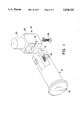
- FIG. 1 is a partial perspective view which depicts the primary components of a hybrid plug lock in accordance with the present invention, FIG. 1 also being in part a schematic illustration;
- FIG. 2 is a schematic, side elevation view of a hybrid plug lock in accordance with the invention.
- FIG. 3 is a schematic top plan view of the lock of FIG. 2;
- FIGS. 4-7 are schematic views, looking from the right end as the lock is depicted in FIGS. 1-3, which illustrate in step-wise fashion the operation of the disclosed embodiment of the invention.
- a hybrid plug lock in accordance with the present invention includes three major components. These components are a cylinder plug, indicated generally at 10, a spring-loaded drive pin 12 and a deadlocking bolt, indicated generally at 14.
- plug 10 will cooperate, in the conventional manner, with a cylinder shell 13 to define a cylinder, i.e., a complete operating lock consisting of the plug, shell, tumblers, springs, plug retainer and all other necessary operating parts.
- plug 10 and shell 13 have been shown schematically.
- the cylinder will be removably received in a bore provided therefor in the tubular shaft of a T-handle.
- Plug 10 will, of course, define a keyway 16 which receives the operating key. Insertion of a key having the proper profile, i.e., cross-sectional shape, and bitting into keyway 16 will result in displacement of the bottom pins of the cylinder so as to align all of the pin tumbler surfaces with a shear line between the plug and shell thus permitting rotation of the plug relative to the shell.
- plug 10 is provided with a longitudinal bore having an axis which is parallel to the axis of rotation of plug 10.
- the drive pin 12 is received in this longitudinal bore.
- a compression spring 18, which biases drive pin 12 in the direction of bolt 14, is also received in the bore.
- Bolt 14 includes a body portion 20 from which a cylindrical latch 22 extends.
- the body portion 20 of bolt 14 is provided with a ramped, generally elliptical guide groove 24 which is engaged by the end of drive pin 12.
- the latch 22 has an axis which is oriented generally transversely with respect to the axis of rotation of plug 10.
- Bolt 14 is resiliently biased, by a compression spring indicated schematically at 26, in the direction of the axis of latch 22.
- Bolt 14 is received in a rectangular channel provided in an extension of shell 13 as may be seen from FIGS. 2 and 3.
- FIG. 4 illustrates the lock of FIGS. 1-3 with the cylinder locked, i.e., with the latch 22 engaged in a complementary opening in the tubular housing, not shown, which receives the tubular shaft of the T-handle, and with the key removed.
- the T-handle will be pushed into its receiving recess so as to be essentially flush with the outer surface of the machine in which installed.
- the free end of drive pin 12 is in the deepest portion of guide groove 24 and the bolt 14 is deadlocked.
- FIG. 5 depicts the state of the lock after a proper key has been inserted in keyway 16 and plug 10 rotated through an angle of approximately 100°.
- the rotation of plug 10 will force bolt 14 inwardly, against the bias of spring 26, to a point where latch 22 will be disengaged from its receiving aperture in the housing of the handle thus permitting the T-handle to "pop out", i.e., the biasing spring behind the T-handle will drive the handle with the cylinder sub-assembly forward.
- the handle will thus, with the lock in the condition depicted in FIG. 5, be in a position for rotation whereby the threaded rod coupled thereto can be unscrewed from its receiver thereby permitting opening of the door of the machine.
- the bolt In the FIG. 5 position, the bolt is not fully depressed, i.e., the T-handle will be released while a portion of the latch 22 remains exposed.
- the handle pops out the bolt will be retained in the position shown in FIG. 5 by contact between the end of latch 22 and the interior of the tubular housing which receives the T-handle.
- FIG. 6 depicts the state of the lock when the plug has been rotated 180°.
- the cylinder may be removed.
- the lock may thus be "rekeyed” by employing a suitable tool to further depress the bolt, which will be accessible through the tubular handle shaft in the space between the handle and the base of the handle receiving recess, so that it does not extend outwardly beyond the outer diameter of the cylinder.
- FIG. 7 depicts the lock when the key has made a complete rotation, i.e., has been turned through 360°.
- the drive pin 12 will have climbed to the top of the ramped portion of guide groove 24.
- the key may be removed from the cylinder. Accordingly, when rotated to the position shown in FIG. 7, the cylinder will be in the locked position, i.e., the drive pin 12 will have returned to the position shown in FIG. 4.
- the T-handle is still in the popped out position and the bolt is retained in the position shown as a result of contact between the end of latch extension 22 and the inner diameter of the tubular T-handle shaft.
- spring 26 in the disclosed embodiment, is not cylindrical but, rather, is elongated at the end thereof disposed away from bolt 14.
- the enlargement may be a single coil, or the spring may be at least partly conically shaped.
- the enlarged end of spring 26 assists in keeping the spring in direct alignment with the bolt as the bolt rises and falls during cylinder operation.
Landscapes
- Lock And Its Accessories (AREA)
- Control Of Vending Devices And Auxiliary Devices For Vending Devices (AREA)
Priority Applications (2)
| Application Number | Priority Date | Filing Date | Title |
|---|---|---|---|
| US08/479,759 US5630332A (en) | 1995-06-07 | 1995-06-07 | Hybrid plug lock |
| CA002178429A CA2178429A1 (fr) | 1995-06-07 | 1996-06-06 | Serrure a barillet hybride |
Applications Claiming Priority (1)
| Application Number | Priority Date | Filing Date | Title |
|---|---|---|---|
| US08/479,759 US5630332A (en) | 1995-06-07 | 1995-06-07 | Hybrid plug lock |
Publications (1)
| Publication Number | Publication Date |
|---|---|
| US5630332A true US5630332A (en) | 1997-05-20 |
Family
ID=23905309
Family Applications (1)
| Application Number | Title | Priority Date | Filing Date |
|---|---|---|---|
| US08/479,759 Expired - Fee Related US5630332A (en) | 1995-06-07 | 1995-06-07 | Hybrid plug lock |
Country Status (2)
| Country | Link |
|---|---|
| US (1) | US5630332A (fr) |
| CA (1) | CA2178429A1 (fr) |
Cited By (9)
| Publication number | Priority date | Publication date | Assignee | Title |
|---|---|---|---|---|
| US20040020251A1 (en) * | 2000-10-25 | 2004-02-05 | Dieter Ramsauer | Closing cylinder |
| US6722171B1 (en) * | 2002-12-11 | 2004-04-20 | Wah Yuet (Ng's) Co., Ltd. | Assembled lock cylinder for door locks |
| US20090002955A1 (en) * | 2007-06-29 | 2009-01-01 | Chi Mei Communication Systems, Inc. | Latching mechanism for portable electronic device |
| US9003845B2 (en) | 2002-01-03 | 2015-04-14 | Master Lock Company Llc | Lock apparatus and method |
| US9514385B2 (en) | 2009-05-01 | 2016-12-06 | Hy-Ko Products Company | Key blank identification system with groove scanning |
| US9582734B2 (en) | 2009-05-01 | 2017-02-28 | Hy-Ko Products Company | Key blank identification system with bitting analysis |
| US9656332B2 (en) | 2006-01-23 | 2017-05-23 | Hy-Ko Products Company | Key duplication machine |
| US9682432B2 (en) | 2006-01-23 | 2017-06-20 | Hy-Ko Products Company | Key duplication machine |
| US9818041B2 (en) | 2015-08-03 | 2017-11-14 | Hy-Ko Products Company | High security key scanning system |
Citations (6)
| Publication number | Priority date | Publication date | Assignee | Title |
|---|---|---|---|---|
| US1724025A (en) * | 1928-01-06 | 1929-08-13 | Briggs & Stratton Corp | Lock |
| US2275362A (en) * | 1940-11-08 | 1942-03-03 | Yale & Towne Mfg Co | Lock |
| US3299678A (en) * | 1964-07-08 | 1967-01-24 | Illinois Lock Co | Lock device for vending machine or the like |
| US3438227A (en) * | 1966-07-13 | 1969-04-15 | Illinois Lock Co | Pop handle lock |
| US4715201A (en) * | 1984-11-08 | 1987-12-29 | Valhi, Inc. | Cylinder lock with removable plug |
| US5212972A (en) * | 1992-06-15 | 1993-05-25 | The Eastern Company | Tamper resistant pop-handle lock |
-
1995
- 1995-06-07 US US08/479,759 patent/US5630332A/en not_active Expired - Fee Related
-
1996
- 1996-06-06 CA CA002178429A patent/CA2178429A1/fr not_active Abandoned
Patent Citations (6)
| Publication number | Priority date | Publication date | Assignee | Title |
|---|---|---|---|---|
| US1724025A (en) * | 1928-01-06 | 1929-08-13 | Briggs & Stratton Corp | Lock |
| US2275362A (en) * | 1940-11-08 | 1942-03-03 | Yale & Towne Mfg Co | Lock |
| US3299678A (en) * | 1964-07-08 | 1967-01-24 | Illinois Lock Co | Lock device for vending machine or the like |
| US3438227A (en) * | 1966-07-13 | 1969-04-15 | Illinois Lock Co | Pop handle lock |
| US4715201A (en) * | 1984-11-08 | 1987-12-29 | Valhi, Inc. | Cylinder lock with removable plug |
| US5212972A (en) * | 1992-06-15 | 1993-05-25 | The Eastern Company | Tamper resistant pop-handle lock |
Cited By (19)
| Publication number | Priority date | Publication date | Assignee | Title |
|---|---|---|---|---|
| US7146833B2 (en) * | 2000-10-25 | 2006-12-12 | Dieter Ramsauer | Closing cylinder |
| US20040020251A1 (en) * | 2000-10-25 | 2004-02-05 | Dieter Ramsauer | Closing cylinder |
| US9003845B2 (en) | 2002-01-03 | 2015-04-14 | Master Lock Company Llc | Lock apparatus and method |
| US6722171B1 (en) * | 2002-12-11 | 2004-04-20 | Wah Yuet (Ng's) Co., Ltd. | Assembled lock cylinder for door locks |
| US9815126B2 (en) | 2006-01-23 | 2017-11-14 | Hy-Ko Products Company | Key duplication machine |
| US10421133B2 (en) | 2006-01-23 | 2019-09-24 | Hy-Ko Products Company | Key duplication machine |
| US9656332B2 (en) | 2006-01-23 | 2017-05-23 | Hy-Ko Products Company | Key duplication machine |
| US9682432B2 (en) | 2006-01-23 | 2017-06-20 | Hy-Ko Products Company | Key duplication machine |
| US9687920B2 (en) | 2006-01-23 | 2017-06-27 | Hy-Ko Products Company | Key duplication machine |
| US9925601B2 (en) | 2006-01-23 | 2018-03-27 | Hy-Ko Products Company | Key duplication machine |
| US20090002955A1 (en) * | 2007-06-29 | 2009-01-01 | Chi Mei Communication Systems, Inc. | Latching mechanism for portable electronic device |
| US7898816B2 (en) * | 2007-06-29 | 2011-03-01 | Chi Mei Communication Systems, Inc. | Latching mechanism for portable electronic device |
| US9934448B2 (en) | 2009-05-01 | 2018-04-03 | Hy-Ko Products Company | Key blank identification system with groove scanning |
| US9582734B2 (en) | 2009-05-01 | 2017-02-28 | Hy-Ko Products Company | Key blank identification system with bitting analysis |
| US9514385B2 (en) | 2009-05-01 | 2016-12-06 | Hy-Ko Products Company | Key blank identification system with groove scanning |
| US11227181B2 (en) | 2009-05-01 | 2022-01-18 | Hy-Ko Products Company Llc | Key blank identification system with groove scanning |
| US9818041B2 (en) | 2015-08-03 | 2017-11-14 | Hy-Ko Products Company | High security key scanning system |
| US10956772B2 (en) | 2015-08-03 | 2021-03-23 | Hy-Ko Products Company | High security key scanning system |
| US11842554B2 (en) | 2015-08-03 | 2023-12-12 | Hy-Ko Products Company Llc | High security key scanning system |
Also Published As
| Publication number | Publication date |
|---|---|
| CA2178429A1 (fr) | 1996-12-08 |
Similar Documents
| Publication | Publication Date | Title |
|---|---|---|
| US3509748A (en) | Axial pin tumbler lock | |
| US3589153A (en) | Key operated lock | |
| US4823575A (en) | Cylinder lock and key | |
| EP1003949B1 (fr) | Serrure a cylindre electromecanique avec ouverture par rotation | |
| US6578396B2 (en) | Removable cylindrical lock core | |
| US5212972A (en) | Tamper resistant pop-handle lock | |
| US5070715A (en) | Interchangeable lock core cylinder | |
| US5630332A (en) | Hybrid plug lock | |
| US2098189A (en) | Key actuated locking bolt | |
| US4272975A (en) | Cylinder lock with key removable core | |
| US4315420A (en) | Retained key double cylinder deadbolt | |
| NZ247719A (en) | Pin-tumbler lock with supplementary pin retainer | |
| US4083211A (en) | Axial split-pin tumbler-type lock mechanism for a handle lock | |
| EP0960245B1 (fr) | Systeme ameliore de serrure a cylindre | |
| GB2556336A (en) | Improvements to lock cylinders | |
| US5010754A (en) | Lock actuator with removable operator | |
| US4593546A (en) | High security cylinder operated deadbolt lock | |
| US4107966A (en) | Selectively rotatable cylinder for a lock | |
| KR101833414B1 (ko) | 안전래치볼트가 구비된 도어락 모티스 | |
| US5551263A (en) | Lock with dead bolt camming action on 90 degree lock cylinder rotation | |
| US752624A (en) | Lil ho | |
| GB2224071A (en) | Padlock with removable cylinder and re-inforced shackle | |
| US20040129044A1 (en) | Multifunction lock cylinder | |
| US4590777A (en) | Doorlock | |
| US20200378151A1 (en) | Lock and key therefor |
Legal Events
| Date | Code | Title | Description |
|---|---|---|---|
| AS | Assignment |
Owner name: KABA HIGH SECURITY LOCKS, CONNECTICUT Free format text: ASSIGNMENT OF ASSIGNORS INTEREST;ASSIGNORS:ALDIERI, RAYMOND;DIVITO, THOMAS J.;HUMPHRY, EDWARD F.;REEL/FRAME:007546/0267 Effective date: 19950606 |
|
| FEPP | Fee payment procedure |
Free format text: PAYOR NUMBER ASSIGNED (ORIGINAL EVENT CODE: ASPN); ENTITY STATUS OF PATENT OWNER: LARGE ENTITY |
|
| FPAY | Fee payment |
Year of fee payment: 4 |
|
| AS | Assignment |
Owner name: UBS, AG ZURICH, SWITZERLAND Free format text: SECURITY AGREEMENT;ASSIGNORS:KABA CORPORATION;KABA ILCO CORPORATION;KABA HIGH SECURITY LOCKS CORPORATION;AND OTHERS;REEL/FRAME:012495/0716 Effective date: 20011001 |
|
| AS | Assignment |
Owner name: KABA CORPORATION, CONNECTICUT Free format text: RELEASE AND TERMINATION;ASSIGNOR:UBS AG, ZURICH;REEL/FRAME:015980/0516 Effective date: 20041102 Owner name: KABA ILCO CORPORATION, NORTH CAROLINA Free format text: RELEASE AND TERMINATION;ASSIGNOR:UBS AG, ZURICH;REEL/FRAME:015980/0516 Effective date: 20041102 Owner name: KABA HIGH SECURITY LOCKS CORPORATION, NORTH CAROLI Free format text: RELEASE AND TERMINATION;ASSIGNOR:UBS AG, ZURICH;REEL/FRAME:015980/0516 Effective date: 20041102 Owner name: ILCO UNICAN PROPERTIES, INC., NORTH CAROLINA Free format text: RELEASE AND TERMINATION;ASSIGNOR:UBS AG, ZURICH;REEL/FRAME:015980/0516 Effective date: 20041102 Owner name: KABA MAS CORPORATION, KENTUCKY Free format text: RELEASE AND TERMINATION;ASSIGNOR:UBS AG, ZURICH;REEL/FRAME:015980/0516 Effective date: 20041102 Owner name: KABA BENZING AMERICA, INC., FLORIDA Free format text: RELEASE AND TERMINATION;ASSIGNOR:UBS AG, ZURICH;REEL/FRAME:015980/0516 Effective date: 20041102 |
|
| FPAY | Fee payment |
Year of fee payment: 8 |
|
| REMI | Maintenance fee reminder mailed | ||
| LAPS | Lapse for failure to pay maintenance fees | ||
| STCH | Information on status: patent discontinuation |
Free format text: PATENT EXPIRED DUE TO NONPAYMENT OF MAINTENANCE FEES UNDER 37 CFR 1.362 |
|
| FP | Lapsed due to failure to pay maintenance fee |
Effective date: 20090520 |