US5630320A - Gas turbine combustor and gas turbine - Google Patents
Gas turbine combustor and gas turbine Download PDFInfo
- Publication number
- US5630320A US5630320A US08/357,187 US35718794A US5630320A US 5630320 A US5630320 A US 5630320A US 35718794 A US35718794 A US 35718794A US 5630320 A US5630320 A US 5630320A
- Authority
- US
- United States
- Prior art keywords
- stabilizer
- cylindrical part
- gas turbine
- combustor
- members
- Prior art date
- Legal status (The legal status is an assumption and is not a legal conclusion. Google has not performed a legal analysis and makes no representation as to the accuracy of the status listed.)
- Expired - Lifetime
Links
Images


Classifications
-
- F—MECHANICAL ENGINEERING; LIGHTING; HEATING; WEAPONS; BLASTING
- F23—COMBUSTION APPARATUS; COMBUSTION PROCESSES
- F23R—GENERATING COMBUSTION PRODUCTS OF HIGH PRESSURE OR HIGH VELOCITY, e.g. GAS-TURBINE COMBUSTION CHAMBERS
- F23R3/00—Continuous combustion chambers using liquid or gaseous fuel
-
- F—MECHANICAL ENGINEERING; LIGHTING; HEATING; WEAPONS; BLASTING
- F23—COMBUSTION APPARATUS; COMBUSTION PROCESSES
- F23R—GENERATING COMBUSTION PRODUCTS OF HIGH PRESSURE OR HIGH VELOCITY, e.g. GAS-TURBINE COMBUSTION CHAMBERS
- F23R3/00—Continuous combustion chambers using liquid or gaseous fuel
- F23R3/28—Continuous combustion chambers using liquid or gaseous fuel characterised by the fuel supply
- F23R3/34—Feeding into different combustion zones
- F23R3/346—Feeding into different combustion zones for staged combustion
-
- F—MECHANICAL ENGINEERING; LIGHTING; HEATING; WEAPONS; BLASTING
- F23—COMBUSTION APPARATUS; COMBUSTION PROCESSES
- F23R—GENERATING COMBUSTION PRODUCTS OF HIGH PRESSURE OR HIGH VELOCITY, e.g. GAS-TURBINE COMBUSTION CHAMBERS
- F23R3/00—Continuous combustion chambers using liquid or gaseous fuel
- F23R3/02—Continuous combustion chambers using liquid or gaseous fuel characterised by the air-flow or gas-flow configuration
- F23R3/16—Continuous combustion chambers using liquid or gaseous fuel characterised by the air-flow or gas-flow configuration with devices inside the flame tube or the combustion chamber to influence the air or gas flow
- F23R3/18—Flame stabilising means, e.g. flame holders for after-burners of jet-propulsion plants
Definitions
- This invention relates to a gas turbine combustor and a gas turbine provided with the gas turbine combustor and, particularly to a gas turbine combustor having a stabilizer for stabilizing flames in premixed fuel air combustion and a gas turbine provided with such a combustor.
- gas turbine combustors in which fuel and combustion air are premixed and then burnt, that is, so called premixing combustion is employed, are increasing, as disclosed in JP A 3-175211.
- the premixing combustion combustor has two advantages at least. One of them is the ability to shorten flames, because premixed fuel and combustion air is injected from a nozzle and it is unnecessary to provide an area for mixing fuel and combustion air at a downstream side of the nozzle. Another is the ability to reduce NOx emission. In the premixing combustion, it is possible to effect combustion under a fuel lean condition. The combustion can reduce NOx emission but lacks stability of flames.
- a stabilizer is provided for the premixing combustion in which fuel is lean.
- the stabilizer serves for stabilizing flames and reducing NOx emission.
- the stabilizer is disposed at a position at which the stabilizer is exposed to a high temperature and large temperature difference caused by starting and stopping of the gas turbine, so that large thermal stress is induced in the stabilizer and the stabilizer may be broken.
- An object of the invention is to provide a gas turbine combustor with a stabilizer having a sufficient stabilizing function of flames, which has minimized thermal stresses generated in the stabilizer even if a large temperature difference is applied to the stabilizer and a high reliability, and a gas turbine having the above-mentioned combustor.
- the present invention is characterized in that a stabilizer is provided at a downstream side of a fuel air supply device for supplying fuel air into a combustion chamber such as a premixing device for premixing and supplying fuel and combustion air into the combustion chamber, the stabilizer having a cylindrical part extending axially from an upstream end thereof to a downstream end and a stabilizing part at the downstream end of the cylindrical part for stabilizing a flame, and the stabilizer is mounted on an inside of the combustor so as to restrict the stabilizer to move radially and axially while allowing deformation of the stabilizer caused by to thermal stresses applied therein.
- the stabilizing part is disposed downstream of and near an outlet port of the premixing device and mounted on the combustor by a mounting device which comprises a plurality of members each radially extending and secured to the inside of the combustor at ends thereof and having a part slidablely fitted in one of holes formed in the cylindrical part to restrict axial movement of the stabilizer while allowing deformation due to thermal stresses and another part supporting an upstream end portion of the cylindrical part of the stabilizer to restrict radial movement of the stabilizer.
- the stabilizing part prefferably has a section taken along an axis of the stabilizer that increases in thickness thereof toward a downstream side.
- the stabilizer formed as mentioned above, even if the stabilizer is deformed into such a shape such as a flared bell due to thermal stresses, the stabilizer can be held stablely without restricting deformation of the cylindrical part, whereby minimized thermal stresses are produced in the cylindrical part of the stabilizer even if the combustor is repeatedly subjected to firing and extinguishing. The stabilizer is prevented from being damaged, whereby the reliability of the combustion is raised.
- FIG. 1 is a vertical sectional view of a gas turbine combustor for explaining an initial stage combustion state
- FIG. 2 is a vertical sectional view of a gas turbine combustor for explaining an intermediate stage combustion state
- FIG. 3 is a vertical sectional view of a gas turbine combustor for explaining a steady state combustion state
- FIG. 4 is a sectional view of a part of the gas turbine combustor showing an example of a mounting portion of a stabilizer to the combustor;
- FIG. 5 is a sectional view of a part of the gas turbine showing another example of the mounting portion of the stabilizer
- FIG. 6 is a sectional view of the stabilizer for explanation of deformation thereof
- FIG. 7 is an explanation view of deformation of the stabilizer
- FIG. 8 is an explanation view of deformation of the stabilizer
- FIGS. 9 and 10 each are an explanation view of stress concentration in the stabilizer mounted on the combustor as shown in FIG. 4;
- FIGS. 11 and 12 each are an explanation of stress concentration of the stabilizer mounted as shown in Fig. 5;
- FIG. 13 is a sectional view of a part of the combustor employing a preferable embodiment of a mounting device
- FIG. 14 is a perspective view of a stabilizer and a portion around the stabilizer
- FIG. 15 is a perspective view of the whole of the stabilizer
- FIG. 16 is a perspective view of a L-shaped plate used for mounting the stabilizer on the combustor
- FIG. 17 is a sectional view of a part of the combustor employing another embodiment of the mounting device.
- FIG. 18 is a perspective view of member parts used for the mounting device as shown in FIG. 17;
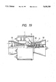
- FIG. 19 is a sectional view of a gas turbine.
- a combustor 1 has a housing formed of a casing 101 and an end plate 102 fixed thereto.
- a first stage combustion cylinder 5 and a second stage combustion cylinder 6 are provided for defining a first stage combustion chamber 16 and a second stage combustion chamber 17, respectively.
- a plurality of first stage fuel nozzles 2 arranged annularly are mounted on the end plate 102 for injecting first stage fuel into the first stage combustion cylinder 5.
- An auxiliary burner fuel nozzle 3 is mounted on the end plate 102 to be positioned at a center of the plurality of first stage fuel nozzles 2.
- a premixing device 12 is provided for premixing second stage fuel and combustion air to form a mixture thereof.
- the premixing device 12 comprises an outer premixing cylinder 30a and an inner premixing cylinder 30b to form an annular premixture path 15 therebetween, as shown in FIG. 4.
- a plurality of second stage fuel nozzles 4 are provided to be disposed in the premixture path 15, and a plurality of inlets 9 for second stage combustion air are provided.
- air of high pressure is introduced from a compressor (not shown) into the interior of the combustor 1.
- a part of the air is introduced in the first stage combustion chamber 16 through inlets and used for first stage combustion of first stage fuel 7 injected through the first stage fuel nozzles 2, and another part is introduced into the premixing device 12 through the inlets 9 to be premixed with second stage fuel 8 injected by the second stage fuel nozzles 4 to produce a premixture or premixture stream 15a of the fuel and the air.
- the premixture stream 15a is introduced in the second stage combustion chamber 17 to effect second stage combustion.
- a stabilizer 13 is provided on second stage premixture flow near a premixing device outlet 12a and at a downstream side of the premixing device outlet 12a.
- first stage fuel 7 and auxiliary burner fuel 14 are injected into the first stage combustion chamber 16 through the first stage fuel nozzles 2 and the auxiliary burner fuel nozzle 3 and then fired. Under this condition, a turbine is started to operate. Conditions of flames 18 and 19 generated at this time are illustrated in FIG. 1.
- a premixture stream 15a in the second stage combustion chamber 17 is ignited.
- second stage fuel 8 is mixed with combustion air 11 in the premixing device 12, the mixture is supplied, as the second stage premixture stream 15a, into the second stage combustion chamber 17.
- the second stage premixture stream 15a is fired to generate second stage combustion flame 20, as shown in FIG. 2.
- provision of the stabilizer 13 makes it possible to effect stable combustion even if fuel concentration in the second stage premixture stream 15a is lean, and to effect stable combustion only by the second stage combustion flame 20 even if the first stage combustion flame 18 is extinguished.
- auxiliary burner fuel 14 supplied from the auxiliary burner fuel nozzle 3 is stopped, the auxiliary burner fuel 14 is joined to the first stage fuel 7, and they are supplied from the first stage fuel nozzles 2, whereby the auxiliary burner flame 19 is extinguished. Then, the first stage combustion flame 18 flows by vortex flows, so that the flames are not held in the first combustion chamber 16. The first stage combustion flame is stabilized by the second stage combustion flame 20. This condition of the flames is illustrated in FIG. 3.
- the stabilizer 13 has important roles in the combustion processes. One of the roles is to secure stability of combustion in the second and third combustion steps as shown in FIGS. 2 and 3 and another is to reduce NOx concentration in combustion gases which are used for driving the gas turbine.
- the stabilizer 13 is mounted on the inside of the combustor 1 such as on the premixing device 12 at its end portion as shown in FIG. 4, for example.
- the stabilizer 13 consists of a cylindrical part 23 and a stabilizing part 22 for stabilizing the flame.
- the cylindrical part 23 has substantially uniform thickness and extends axially, that is, in a length direction of the combustor 1, from an upstream end of the cylindrical part 23 to a downstream end.
- the stabilizing part 22 extends from the downstream end of the cylindrical part 23 to the downstream side and is shaped in a ring. Preferably, it has an axially taken section shaped as a trapezoid and the thickness of the section increases toward the downstream side of the premixture stream 15a.
- the cylindrical part 23 extends axially from one of the parallel sides of the trapezoid, which is shorter than the other parallel side.
- the stabilizer 13 is mounted on the premixing device 12 so that the stabilizing part 22 is positioned at such a position that it is in the premixture stream 15a, near the outlet 12a of the premixing device 12 and at a downstream side of the outlet 12a.
- the cylindrical part 23 of the stabilizer 13 is fixed to the premixing device 12 by a plurality of members such as flat plates 27 (for example, 16 plates) arranged angularly at regular intervals.
- the flat plates 27 each are disposed in the flow path of the premixing device 12 so that major surfaces of the flat plate 27 are in parallel to the length direction of the combustor 1, whereby the outlet 12a of the premixing device 12 is divided into a plurality of ports.
- the stabilizer 13 is joined to the outer and inner premixing cylinders 30a and 30b through the flat plates 27 welded at positions 28 and 29 as shown in FIG. 4.
- FIG. 5 Another example of the mounting of the stabilizer 13 is shown in FIG. 5.
- a plurality of flat plates 27 are used to connect the stabilizer 13 to the premixing device 12.
- Each of the flat plates 27 has a long slit for inserting the cylindrical part 23 therein.
- Each is also welded to the cylindrical part 23 and the outer and inner premixing device cylinders 30a and 30b, with welded portions 28 and 29 being provided.
- the slit extends to the stabilizing part 22, the welding portion 29 also extends thereto.
- Second stage premixture stream 15a contacts an inclined side part of the trapezoidal section and outer and inner peripheries of the cylindrical part 23.
- the second stage premixture stream 15a is not burning, so that the temperature of the stream 15a is near the temperature of inflow air 11. Therefore, the temperature of the inclined side portion of the trapezoidal section of the stabilizing part 22 and the temperature of the outer and inner peripheries of the cylindrical part 23 each are relatively low. Therefore, during the operation of the combustor 1, the stabilizer 13 is deformed so that the diameter of the end face 21 of the stabilizing part 22 expands.
- the flame is in contact with the end face 21 of the stabilizer 13 and the second stage premixture stream 15a is in contact with the inclined side portions of the trapezoidal section of the stabilizing part 22 and the outer and inner peripheries of the cylindrical part 23, so that the end face 21 of the stabilizing part 22 increases in temperature and the temperature of the outer and inner peripheries of the cylindrical part 23 and the inclined side portion of the trapezoidal section of the stabilizing part 22 decreases as it becomes farther from the end face 21.
- an end portion of the stabilizer 13 have the higher temperature deforms to a relatively large extent and an upstream side portion of the stabilizer 13 of which the temperature is relatively low deforms to a small extent. Therefore, since the stabilizer 13 is cylindrical as a whole, the stabilizer 13 deforms in a flared bell shape as shown in FIG. 6.
- FIGS. 7 and in FIG. 8 The deformation conditions of the stabilizer 13 fixed to the premixing device 12, as shown in FIG. 4 and in FIG. 5, are shown in FIG. 7 and in FIG. 8, respectively.
- dimensions of DX, DY and DZ represent deformation amounts in directions of X, Y, Z, respectively.
- Positions in which the maximum stress occurs are shown in FIGS. 9 to 12, wherein it is shown in FIGS. 9 and 10 the case of the fixing of the stabilizer 13 as shown in FIG. 4, and the FIGS. 11 and 12 in case of the fixing of the stabilizer 13 shown in FIG. 5.
- the stabilizer 13 deforms outside in a flared bell shape, and since the deformation is restricted by the fixing means such as the flat plate 27, large thermal stress is induced in the stabilizer or the flat plate 27.
- the maximum stress is induced in the cylindrical part 23 as shown by the black marks in FIGS. 9 to 10 when the stabilizer 13 is fixed as shown in FIG. 4, and in the flat plate 27 as shown by the black marks in FIGS. 11, 12 when fixed as shown in FIG. 5.
- FIGS. 13 to 16 an embodiment of the mounting device of the stabilizer 13 is explained hereunder.
- a premixing device 12 is of the same construction as in FIG. 4 except that premixing outer and inner cylinders 35, 34 each have fixing openings 37, 38.
- the premixing outer and inner cylinders 35, 34 each have the slit-like openings 37, 38 arranged annularly at regular intervals around the outlet 12a of the premixing passage 15 defined by the cylinders 37, 38.
- the length direction of the openings 37, 38 is in the axial direction of the premixing device 12.
- the openings 37 of the premixing outer cylinder 35 extend radially and are aligned with the openings 38 of the remixing inner cylinder 34, respectively.
- the stabilizer 13 is cylindrical as a whole, as shown in FIGS. 14, 15 and consists of a cylindrical part 23 axially extending from an upstream end to a downstream end and a stabilizing part 22 axially extending from the downstream end toward a downstream side for stabilizing the flame.
- the cylindrical part 23 has a plurality of slit-like openings 39 (for example, 16 openings) arranged in a circumferetial direction at regular intervals.
- the length direction of each opening 39 is in the axial direction of the
- the stabilizer 13 is mounted on an inside of the combustor 1, for example, on the premixing device 12.
- a mounting device for mounting the stabilizer 13 on the premixing device 12 includes a plurality of members such as L-shaped plates 31 each of which is shaped as shown in FIG. 16.
- the L-shaped plate 31 has a radial projection part 31a and an axial projection part 3lb.
- the L-shaped plate 31 is inserted in the opening 38 with a narrow width end 31c.
- the radial projection part 31a is inserted in the opening 39 of the stabilizer 13 and then the narrow width end 31c of the part 31 is inserted in the opening 37 of the premixing outer cylinder 35.
- the narrow width end 31c is secured to the premixing outer cylinder 35 by welding.
- the wider width end 31d is secured to the premixing inner cylinder 34 by welding.
- the axial projection part 3lb is fitted in the inside of the cylindrical part of the stabilizer 13 so as to support the inside of the cylindrical part 23, thereby to restrict radial movement of the stabilizer 13.
- the upstream end of the cylindrical part 23 of the stabilizer 13, which upstream end is free from deformation due to thermal stress, is welded to the axial projection part 3lb although the welding is not necessarily needed for mounting the stabilizer 13.
- the welding can prevent vibrations of the stabilizer 13.
- the radial projection 31a is slidablely inserted in the opening 39 of the stabilizer 13 to allow deformation which may be caused in the stabilizer 13 due to thermal stresses.
- the insertion of the radial projection in the opening 39 can surely prevent the stabilizer 13 from axially moving.
- seal plates 36 are provided for sealing air passing through annular gaps between the second stage combustion cylinder 6 and the premixing outer cylinder 35 and between the premixing inner cylinder 34 and the first stage combustion cylinder 5, and for supporting the end portion of the premixing device 12.
- FIGS. 17 and 18 Another embodiment of the mounting device for mounting the stabilizer 13 on the combustor 1 is described referring to FIGS. 17 and 18.
- the mounting device includes two flat plates 40, 41 instead of the L-shaped plate.
- the plates 40 each are slidablely inserted in the slit-like opening 39 of the cylindrical part 23 of the stabilizer 13 and both ends 40a, 40b of each plate 40 are secured to the premixing outer and inner cylinders 35, 34 by welding 33.
- the stabilizer 13 can move radially but not move axially by the flat plate 40.
- the flat plate 41 is elongate and has a groove 41c extending perpendicularly to the length direction.
- the flat plate 41 is inserted in the slit-like openings 37, 38 of the premixing outer and inner cylinders 35, 34 and secured to the cylinders 35,34 by welding 33.
- the upstream end of the cylindrical part 23 of the stabilizer 13 is inserted in the groove 41a so that the stabilizer 13 is restricted to move radially.
- the flat plate 41 is assembled in the premixing device 12, then the stabilizer 13 inserted in the groove 41a, and finally, the flat plate 40 is assembled in the premixing device 12.
- This mounting device as shown in FIG. 17 and FIG. 18 has the same function as the previously mentioned mounting device as shown in FIG. 13.
- flat plates are used for mounting the stabilizer on the inside of the combustor, so that the rigidity of the premixing device is increased, whereby deformation by pressure or hydraulic force applied on the premixing device can be prevented.
- the flat plates divide the annular premixture passage into the plurality of outlet ports, whereby the premixture stream can be rectified and combustion efficiency can be raised.
- the gas turbine comprises a gas turbine 52 having stationary blades 50 and moving blades 51, a compressor 53 connected to the gas turbine 52 for compressing air and introducing compressed air into a combustor 1 for combustion and cooling, and a combustor 54 for generating combustion gas of high temperature and high pressure.
- a part of the compressed air delivered from the compressor 53 is introduced into the combustor 1 and used for combustion of fuel in the combustion chamber. Another part of the compressed air is used as cooling air for cooling liners of the combustor 1 and the blades 50, 51 of the turbine 52.
- the combustion gas H of high temperature and high pressure is injected onto the moving blades 51 through the stationary blades 50 to drive the turbine 52.
- a generator (not shown), in general, is connected to a shaft 55 of the gas turbine 52 and driven by the shaft 55 to generate electric power.
- the combustor 1 associated in the gas turbine may be constructed according to any one of embodiments previously mentioned.
Landscapes
- Engineering & Computer Science (AREA)
- Chemical & Material Sciences (AREA)
- Combustion & Propulsion (AREA)
- Mechanical Engineering (AREA)
- General Engineering & Computer Science (AREA)
- Gas Burners (AREA)
- Pre-Mixing And Non-Premixing Gas Burner (AREA)
Abstract
Description
Claims (16)
Applications Claiming Priority (2)
| Application Number | Priority Date | Filing Date | Title |
|---|---|---|---|
| JP5-314685 | 1993-12-15 | ||
| JP5314685A JP2904701B2 (en) | 1993-12-15 | 1993-12-15 | Gas turbine and gas turbine combustion device |
Publications (1)
| Publication Number | Publication Date |
|---|---|
| US5630320A true US5630320A (en) | 1997-05-20 |
Family
ID=18056322
Family Applications (1)
| Application Number | Title | Priority Date | Filing Date |
|---|---|---|---|
| US08/357,187 Expired - Lifetime US5630320A (en) | 1993-12-15 | 1994-12-13 | Gas turbine combustor and gas turbine |
Country Status (5)
| Country | Link |
|---|---|
| US (1) | US5630320A (en) |
| JP (1) | JP2904701B2 (en) |
| KR (1) | KR0153812B1 (en) |
| CN (1) | CN1104592C (en) |
| TW (1) | TW253027B (en) |
Cited By (13)
| Publication number | Priority date | Publication date | Assignee | Title |
|---|---|---|---|---|
| US5984662A (en) * | 1997-07-31 | 1999-11-16 | Superior Fireplace Company | Karman vortex generating burner assembly |
| US6575733B1 (en) * | 1997-11-10 | 2003-06-10 | Gourmeli International N.V. | Fuel combustion method and reactor |
| US20030152878A1 (en) * | 1997-11-10 | 2003-08-14 | Staffler Franz Josef | Streamlined body and combustion apparatus |
| US20050026096A1 (en) * | 2001-11-23 | 2005-02-03 | Staffler Franz Josef | Streamlined body and combustion apparatus having such a streamlined body |
| US20050028526A1 (en) * | 2003-06-06 | 2005-02-10 | Ralf Sebastian Von Der Bank | Burner for a gas-turbine combustion chamber |
| US20100071376A1 (en) * | 2008-09-24 | 2010-03-25 | Siemens Energy, Inc. | Combustor Assembly in a Gas Turbine Engine |
| US20150159877A1 (en) * | 2013-12-06 | 2015-06-11 | General Electric Company | Late lean injection manifold mixing system |
| US20150308349A1 (en) * | 2014-04-23 | 2015-10-29 | General Electric Company | Fuel delivery system |
| US20160040884A1 (en) * | 2014-08-06 | 2016-02-11 | General Electric Company | Multi-Stage Combustor |
| US10119473B2 (en) | 2015-05-20 | 2018-11-06 | General Electric Company | Component, gas turbine component and method of forming |
| US20210341147A1 (en) * | 2020-05-01 | 2021-11-04 | Mitsubishi Power, Ltd. | Gas Turbine Combustor |
| US11287134B2 (en) * | 2019-12-31 | 2022-03-29 | General Electric Company | Combustor with dual pressure premixing nozzles |
| US11828467B2 (en) | 2019-12-31 | 2023-11-28 | General Electric Company | Fluid mixing apparatus using high- and low-pressure fluid streams |
Families Citing this family (7)
| Publication number | Priority date | Publication date | Assignee | Title |
|---|---|---|---|---|
| CA2537926C (en) * | 2003-09-05 | 2011-01-11 | Delavan Inc. | Pilot combustor for stabilizing combustion in gas turbine engines |
| CN100504175C (en) * | 2006-04-13 | 2009-06-24 | 中国科学院工程热物理研究所 | Nozzle structure of combustion chamber in low heat value of gas turbine, and combustion method |
| US20090211255A1 (en) * | 2008-02-21 | 2009-08-27 | General Electric Company | Gas turbine combustor flame stabilizer |
| US8522553B2 (en) * | 2011-09-14 | 2013-09-03 | General Electric Company | System and method for conditioning a working fluid in a combustor |
| US20140060001A1 (en) * | 2012-09-04 | 2014-03-06 | Alexander R. Beeck | Gas turbine engine with shortened mid section |
| US9127554B2 (en) * | 2012-09-04 | 2015-09-08 | Siemens Energy, Inc. | Gas turbine engine with radial diffuser and shortened mid section |
| US11002190B2 (en) * | 2016-03-25 | 2021-05-11 | General Electric Company | Segmented annular combustion system |
Citations (3)
| Publication number | Priority date | Publication date | Assignee | Title |
|---|---|---|---|---|
| US3236048A (en) * | 1963-09-25 | 1966-02-22 | Gen Motors Corp | Vaporizing manifold and flameholder for afterburners |
| JPH03175211A (en) * | 1989-03-20 | 1991-07-30 | Hitachi Ltd | Combustor, combustor for turbine, burner and method of combustion |
| US8220251B2 (en) * | 2004-11-23 | 2012-07-17 | Johnson Matthey Public Limited Company | Exhaust system comprising exotherm-generating catalyst |
-
1993
- 1993-12-15 JP JP5314685A patent/JP2904701B2/en not_active Expired - Lifetime
-
1994
- 1994-12-07 TW TW083111394A patent/TW253027B/en not_active IP Right Cessation
- 1994-12-13 US US08/357,187 patent/US5630320A/en not_active Expired - Lifetime
- 1994-12-14 CN CN94119018A patent/CN1104592C/en not_active Expired - Lifetime
- 1994-12-15 KR KR1019940034398A patent/KR0153812B1/en not_active IP Right Cessation
Patent Citations (4)
| Publication number | Priority date | Publication date | Assignee | Title |
|---|---|---|---|---|
| US3236048A (en) * | 1963-09-25 | 1966-02-22 | Gen Motors Corp | Vaporizing manifold and flameholder for afterburners |
| JPH03175211A (en) * | 1989-03-20 | 1991-07-30 | Hitachi Ltd | Combustor, combustor for turbine, burner and method of combustion |
| US5216885A (en) * | 1989-03-20 | 1993-06-08 | Hitachi, Ltd. | Combustor for burning a premixed gas |
| US8220251B2 (en) * | 2004-11-23 | 2012-07-17 | Johnson Matthey Public Limited Company | Exhaust system comprising exotherm-generating catalyst |
Cited By (19)
| Publication number | Priority date | Publication date | Assignee | Title |
|---|---|---|---|---|
| US5984662A (en) * | 1997-07-31 | 1999-11-16 | Superior Fireplace Company | Karman vortex generating burner assembly |
| US8979525B2 (en) | 1997-11-10 | 2015-03-17 | Brambel Trading Internacional LDS | Streamlined body and combustion apparatus |
| US6575733B1 (en) * | 1997-11-10 | 2003-06-10 | Gourmeli International N.V. | Fuel combustion method and reactor |
| US20030152878A1 (en) * | 1997-11-10 | 2003-08-14 | Staffler Franz Josef | Streamlined body and combustion apparatus |
| US20050026096A1 (en) * | 2001-11-23 | 2005-02-03 | Staffler Franz Josef | Streamlined body and combustion apparatus having such a streamlined body |
| US20050028526A1 (en) * | 2003-06-06 | 2005-02-10 | Ralf Sebastian Von Der Bank | Burner for a gas-turbine combustion chamber |
| US7621131B2 (en) * | 2003-06-06 | 2009-11-24 | Rolls-Royce Deutschland Ltd & Co. Kg | Burner for a gas-turbine combustion chamber |
| US8375726B2 (en) * | 2008-09-24 | 2013-02-19 | Siemens Energy, Inc. | Combustor assembly in a gas turbine engine |
| US9016066B2 (en) | 2008-09-24 | 2015-04-28 | Siemens Energy, Inc. | Combustor assembly in a gas turbine engine |
| US20100071376A1 (en) * | 2008-09-24 | 2010-03-25 | Siemens Energy, Inc. | Combustor Assembly in a Gas Turbine Engine |
| US20150159877A1 (en) * | 2013-12-06 | 2015-06-11 | General Electric Company | Late lean injection manifold mixing system |
| US9803555B2 (en) * | 2014-04-23 | 2017-10-31 | General Electric Company | Fuel delivery system with moveably attached fuel tube |
| US20150308349A1 (en) * | 2014-04-23 | 2015-10-29 | General Electric Company | Fuel delivery system |
| US20160040884A1 (en) * | 2014-08-06 | 2016-02-11 | General Electric Company | Multi-Stage Combustor |
| US10041681B2 (en) * | 2014-08-06 | 2018-08-07 | General Electric Company | Multi-stage combustor with a linear actuator controlling a variable air bypass |
| US10119473B2 (en) | 2015-05-20 | 2018-11-06 | General Electric Company | Component, gas turbine component and method of forming |
| US11287134B2 (en) * | 2019-12-31 | 2022-03-29 | General Electric Company | Combustor with dual pressure premixing nozzles |
| US11828467B2 (en) | 2019-12-31 | 2023-11-28 | General Electric Company | Fluid mixing apparatus using high- and low-pressure fluid streams |
| US20210341147A1 (en) * | 2020-05-01 | 2021-11-04 | Mitsubishi Power, Ltd. | Gas Turbine Combustor |
Also Published As
| Publication number | Publication date |
|---|---|
| CN1112664A (en) | 1995-11-29 |
| CN1104592C (en) | 2003-04-02 |
| KR0153812B1 (en) | 1998-11-16 |
| TW253027B (en) | 1995-08-01 |
| JPH07167437A (en) | 1995-07-04 |
| KR950019394A (en) | 1995-07-24 |
| JP2904701B2 (en) | 1999-06-14 |
Similar Documents
| Publication | Publication Date | Title |
|---|---|---|
| US5630320A (en) | Gas turbine combustor and gas turbine | |
| US7316117B2 (en) | Can-annular turbine combustors comprising swirler assembly and base plate arrangements, and combinations | |
| CA2578565C (en) | Method and apparatus for gas turbine engines | |
| EP1429078B1 (en) | Apparatus for decreasing gas turbine engine combustor emissions | |
| US5117624A (en) | Fuel injector nozzle support | |
| EP1508743B1 (en) | Combuster swirler assembly | |
| US7080515B2 (en) | Gas turbine can annular combustor | |
| US6148604A (en) | Combustion chamber assembly having a transition duct damping member | |
| EP0700499B1 (en) | A gas turbine engine combustion chamber | |
| US7237384B2 (en) | Counter swirl shear mixer | |
| US6920758B2 (en) | Gas turbine and the combustor thereof | |
| US5671597A (en) | Low nox fuel nozzle assembly | |
| JP4430074B2 (en) | Operation method of burner and gas turbine | |
| JP2005098678A (en) | Method and apparatus for reducing emission of gas turbine engine | |
| KR20150065782A (en) | Combustor with radially staged premixed pilot for improved operability | |
| US10228140B2 (en) | Gas-only cartridge for a premix fuel nozzle | |
| KR20180037044A (en) | Assembly structure and assembly method of seal member, seal member, gas turbine | |
| JP3192055B2 (en) | Gas turbine combustor | |
| JP2005106305A (en) | Nozzle for fuel combustion and fuel supplying method for gas turbine combustor | |
| US7966832B1 (en) | Combustor | |
| EP3309457B1 (en) | Combustion dynamics mitigation system | |
| KR100261498B1 (en) | Combustor of gas turbine engine | |
| JP7165545B2 (en) | Combustor for gas turbine | |
| JP2010236739A (en) | Gas turbine combustor | |
| JPH10169987A (en) | Gas turbine combustor and its operation method |
Legal Events
| Date | Code | Title | Description |
|---|---|---|---|
| AS | Assignment |
Owner name: HITACHI, LTD., JAPAN Free format text: ASSIGNMENT OF ASSIGNORS INTEREST;ASSIGNORS:MATSUDA, NORIAKI;AZUHATA, SHIGERU;MORITOMO, YOSHIKAZU;AND OTHERS;REEL/FRAME:007337/0035 Effective date: 19941124 |
|
| STCF | Information on status: patent grant |
Free format text: PATENTED CASE |
|
| FEPP | Fee payment procedure |
Free format text: PAYOR NUMBER ASSIGNED (ORIGINAL EVENT CODE: ASPN); ENTITY STATUS OF PATENT OWNER: LARGE ENTITY |
|
| FPAY | Fee payment |
Year of fee payment: 4 |
|
| FPAY | Fee payment |
Year of fee payment: 8 |
|
| FPAY | Fee payment |
Year of fee payment: 12 |
|
| AS | Assignment |
Owner name: MITSUBISHI HITACHI POWER SYSTEMS, LTD., JAPAN Free format text: CHANGE OF NAME;ASSIGNOR:HITACHI, LTD.;REEL/FRAME:033003/0648 Effective date: 20140201 |
|
| AS | Assignment |
Owner name: MITSUBISHI HITACHI POWER SYSTEMS, LTD., JAPAN Free format text: CONFIRMATORY ASSIGNMENT;ASSIGNOR:HITACHI, LTD.;REEL/FRAME:033917/0209 Effective date: 20140917 |