US5628929A - Thermal control apparatus and method - Google Patents
Thermal control apparatus and method Download PDFInfo
- Publication number
- US5628929A US5628929A US08/322,666 US32266694A US5628929A US 5628929 A US5628929 A US 5628929A US 32266694 A US32266694 A US 32266694A US 5628929 A US5628929 A US 5628929A
- Authority
- US
- United States
- Prior art keywords
- heater
- thermal energy
- detector
- source
- electrical energy
- Prior art date
- Legal status (The legal status is an assumption and is not a legal conclusion. Google has not performed a legal analysis and makes no representation as to the accuracy of the status listed.)
- Expired - Fee Related
Links
- 238000000034 method Methods 0.000 title claims abstract description 32
- 230000011664 signaling Effects 0.000 claims 2
- 238000004519 manufacturing process Methods 0.000 abstract description 2
- 239000008280 blood Substances 0.000 description 14
- 210000004369 blood Anatomy 0.000 description 14
- 239000000203 mixture Substances 0.000 description 13
- 239000000523 sample Substances 0.000 description 13
- 239000012530 fluid Substances 0.000 description 9
- 238000010586 diagram Methods 0.000 description 5
- 239000011159 matrix material Substances 0.000 description 5
- 238000010339 medical test Methods 0.000 description 4
- 238000011045 prefiltration Methods 0.000 description 4
- 241000725303 Human immunodeficiency virus Species 0.000 description 3
- 239000007787 solid Substances 0.000 description 3
- 239000000853 adhesive Substances 0.000 description 2
- 230000001070 adhesive effect Effects 0.000 description 2
- 238000013459 approach Methods 0.000 description 2
- 239000012472 biological sample Substances 0.000 description 2
- 238000010276 construction Methods 0.000 description 2
- 238000001514 detection method Methods 0.000 description 2
- 230000000694 effects Effects 0.000 description 2
- 238000010438 heat treatment Methods 0.000 description 2
- 101001022148 Homo sapiens Furin Proteins 0.000 description 1
- 101000701936 Homo sapiens Signal peptidase complex subunit 1 Proteins 0.000 description 1
- 102100030313 Signal peptidase complex subunit 1 Human genes 0.000 description 1
- 230000032683 aging Effects 0.000 description 1
- 229910052782 aluminium Inorganic materials 0.000 description 1
- XAGFODPZIPBFFR-UHFFFAOYSA-N aluminium Chemical compound [Al] XAGFODPZIPBFFR-UHFFFAOYSA-N 0.000 description 1
- 238000006243 chemical reaction Methods 0.000 description 1
- 239000003153 chemical reaction reagent Substances 0.000 description 1
- 230000000295 complement effect Effects 0.000 description 1
- 238000013500 data storage Methods 0.000 description 1
- 230000003247 decreasing effect Effects 0.000 description 1
- 239000011888 foil Substances 0.000 description 1
- 230000006870 function Effects 0.000 description 1
- 238000011534 incubation Methods 0.000 description 1
- 230000007774 longterm Effects 0.000 description 1
- 229910052751 metal Inorganic materials 0.000 description 1
- 239000002184 metal Substances 0.000 description 1
- 230000000737 periodic effect Effects 0.000 description 1
- 230000002123 temporal effect Effects 0.000 description 1
Images


Classifications
-
- G—PHYSICS
- G05—CONTROLLING; REGULATING
- G05D—SYSTEMS FOR CONTROLLING OR REGULATING NON-ELECTRIC VARIABLES
- G05D23/00—Control of temperature
- G05D23/19—Control of temperature characterised by the use of electric means
- G05D23/20—Control of temperature characterised by the use of electric means with sensing elements having variation of electric or magnetic properties with change of temperature
- G05D23/24—Control of temperature characterised by the use of electric means with sensing elements having variation of electric or magnetic properties with change of temperature the sensing element having a resistance varying with temperature, e.g. a thermistor
-
- G—PHYSICS
- G05—CONTROLLING; REGULATING
- G05D—SYSTEMS FOR CONTROLLING OR REGULATING NON-ELECTRIC VARIABLES
- G05D23/00—Control of temperature
- G05D23/19—Control of temperature characterised by the use of electric means
- G05D23/1917—Control of temperature characterised by the use of electric means using digital means
Definitions
- Embodiments described herein generally relate to an apparatus and a method for controlling temperature. More specifically, the embodiments relate to an apparatus and a method providing thermal control of an element of an analytical instrument.
- Analytical instruments are available for performing a number of functions. Some analytical instruments perform medical tests on biological samples, such as human blood and the like. These medical tests may determine if, for example, a human blood sample is infected with the AIDS virus. To perform the medical tests, the analytical instrument may mix the blood sample with another fluid, such as reagents and the like. The blood sample reacts with the added fluid. For some of these reactions between the added fluid and the blood sample to take place as intended, it may be desirable to maintain the blood sample/added fluid mixture at a specific temperature. The mixture may need to be kept at that specific temperature for a predetermined period of time. This time period may be referred to as an "incubation period.” Similar concerns about appropriate temperatures for appropriate times may relate to the blood sample and the added fluid separately before mixing.
- the analytical instrument may be provided with a heater of sorts.
- the heater may be positioned near to a vessel holding the blood sample/added fluid mixture.
- a controller is associated with the heater for insuring that the heater supplies the vessel, and thus the mixture, with sufficient heat energy to keep the mixture at the desired, specific temperature for the desired time.
- the analytical instrument may not be able to perform the medical tests as intended. For instance, the instrument may not be able to obtain correct information about the blood sample. Assuming the blood sample were infected with the AIDS virus, if the blood sample/added fluid mixture were not kept at the desired temperature for the desired time period, then the analytical instrument may tell an operator of the instrument that the blood sample is not infected with the AIDS virus. This is undesirable.
- the heater may degrade or age over time.
- the controller may have difficulty in controlling the heater. As the heater ages, the heater may not be able to provide the appropriate heat to the mixture for the proper time period.
- the heat applied to the mixture by the heater may change or vary over time.
- an apparatus includes a heater and a source of electrical energy electrically connected with the heater for energizing the heater to produce thermal energy.
- a driver is electrically connected with the heater and the source of electrical energy for controlling application of electrical energy to the heater.
- a sensor is electrically connected with the heater for detecting thermal energy produced by the heater responsive to the electrical energy from the source of electrical energy.
- a controller is electrically connected with the driver and the sensor for controlling production of thermal energy by the heater responsive to electrical energy from the source of electrical energy.
- Another embodiment provides a method in which a heater is electrically connected with a relatively reduced thermal energy reference resistor.
- An amplifier operatively associated with the heater slews to a relatively reduced thermal energy value which is recorded in memory.
- An algorithm controlling the heater is updated.
- the heater is electrically connected with a detector for sensing thermal energy produced by the heater.
- the amplifier slews to a value associated with the detector.
- a method of thermally controlling an instrument includes electrically connecting a heater with a relatively increased thermal energy reference resistor.
- An amplifier operatively associated with the heater is allowed to slew to a relatively increased thermal energy value.
- the relatively increased thermal energy value is recorded in memory.
- An algorithm controlling the heater is updated.
- the heater is electrically connected with a detector for sensing thermal energy produced by the heater.
- the amplifier is allowed to slew to a value associated with the detector.
- a further embodiment provides a method of thermally controlling an instrument wherein a heater is energized such that the heater produces thermal energy. At least one of a relatively increased temperature reference value and a relatively reduced temperature reference value is consulted while the heater is energized to calibrate the heater.
- Yet another embodiment comprises a method in which a heater is energized with electrical energy to produce thermal energy.
- a thermal energy level produced by the heater is detected with a detector operatively associated with the heater.
- the detected thermal energy level is compared with a predetermined thermal energy level.
- the electrical energy applied to the heater is changed such that the detected thermal energy level is substantially similar to the predetermined thermal energy level.
- FIG. 1 is a general schematic block diagram of an apparatus and a method for thermal control
- FIG. 2 is a schematic diagram of a driver comprising the apparatus shown in FIG. 1;
- FIG. 3 is a schematic diagram of a slave sensor comprising the apparatus of FIG. 1;
- FIGS. 4A, 4B and 4C illustrate schematically a master sensor comprising the apparatus of FIG. 1;
- FIG. 5 is a schematic diagram of a circuit comprising part of the apparatus of FIG. 1;
- FIG. 6 is a flow chart illustrating operation of the apparatus and method of FIG. 1.
- Embodiments disclosed herein relate to apparatuses and methods providing thermal control.
- the apparatuses and methods may be utilized in a number of employments. However, for the sake of clarity of understanding, the embodiments will be discussed with respect to their employment with an analytical instrument.
- the embodiments may be used with the instruments and methods disclosed in U.S. Pat. Nos 5,006,309, 5,089,424, 5,120,199, 5,185,264, 5,198,368 and 5,244,630.
- Those patents are assigned to the assignee of the present case and the disclosures thereof are specifically incorporated herein, in their entirety, by this reference.
- elements of the disclosed embodiments may be combined in any appropriate fashion to arrive at yet further embodiments. Thus, the scope of the claims is not to be limited to the embodiments disclosed herein. To clarify relations among the apparatuses and the methods, both will be discussed simultaneously.
- FIG. 1 One embodiment 10 of a thermal control apparatus and method is illustrated in FIG. 1.
- the embodiment 10 generally comprises a controller 12, a driver 14, a sensor 16, and a heater 18, shown in dotted lines in FIG. 1.
- the heater 18 comprises a source 20 of thermal energy and a detector 22 that detects thermal energy in the heater 18.
- the controller 12 is electrically connected with the driver 14 and the sensor 16.
- the driver 14 is electrically connected with the source 20 of thermal energy.
- the sensor 16 is electrically connected with the detector 22.
- a source 24 of electrical energy is electrically connected with the controller 12, the driver 14 and the sensor 16 for supplying those elements with electrical energy.
- the controller 12 may be a computer having memory and running appropriate routines.
- memory may be a RAM, a ROM, an EPROM, a SRAM and the like.
- the controller 12 comprises a 68HC11 microcontroller available from Motorola (Schaumburg, Ill.).
- the controller 12 may include a digital logic device and memory that are electrically connected with at least one of the driver 14 and the sensor 16. The controller 12 performs appropriate routines, discussed in detail later, for controlling thermal energy in the heater 18.
- the driver 14 generally controls application of electrical energy from the source 24 to the source 20 of thermal energy in the heater 18. Application of electrical energy by the driver 14 to the source 20 is directed by the controller 12.
- the driver 14 may comprise, in one embodiment, a solid state relay and the like.
- the sensor 16 monitors an electrical signal generated by the detector 22 indicative of thermal energy present in the heater 18.
- the sensor 16 sends a complementary signal to the controller 12 such that the controller 12 is provided with information representing the thermal energy present in the heater 18.
- the heater 18, in an exemplary embodiment, may comprise a thermally conductive body, made of a metal such as aluminum and the like, with which the source 20 is operatively associated.
- the source 20 may be operatively associated with the body through a suitable technique, such as adhesive and the like.
- the body in some embodiments, may be constructed to provide at least one of a cover for an item processing path in the instrument, a mechanism for transferring thermal energy from the source 20 to the item being processed, and structural support for instrument components, such as dispensers, washers, aspirators, etc.
- the body is constructed and positioned to assist in providing the desired temperature for the desired time period to the item being processed, such as a biological sample and the like, by the instrument.
- the source 20 of thermal energy may be an electrical heating element, such as a resistive foil heating element with a nominal resistance of about 232 Ohms and a voltage rating of about 120 Volts rms .
- the source 20 may incorporate a thermal energy limiter, such as a self-resetting thermal limit switch and the like.
- the self-resetting thermal limit switch may interrupt flow of electrical current through the source 20 when the temperature of the switch approaches about 80° Celsius and may reset to again allow current flow through the source 20 when the temperature of the switch approaches about 60° Celsius.
- the detector 22 in an exemplary embodiment, is operatively associated with the body through suitable means, such as an adhesive and the like.
- the detector 22 may be of any construction that provides an electrical signal indicative of the thermal energy associated with the heater 18.
- the detector 22 may be a SDI-GR2101 resistive temperature detector available from SDI of Attleboro, Mass. This resistive temperature detector has an electrical resistance R (in Ohms) of about
- T is the temperature in degrees Celsius.
- FIGS. 2 through 6 A particular embodiment is illustrated in FIGS. 2 through 6.
- Those Figures show an embodiment which provides thermal control for a plurality of, specifically six, item processing paths in an analytical instrument. At least one of the processing paths may not be thermally controlled as the other paths are controlled.
- Each processing path includes a plurality of, specifically eight, heaters 18.
- At least one driver 14 (FIG. 2) and at least one sensor 16 (FIG. 3 or FIGS. 4A, 4B and 4C) are dedicated to each processing path.
- one controller 12 is electrically connected with six drivers 14 and six sensors 16.
- One of the sensors 16 is a master sensor 46 (FIGS. 4A, 4B and 4C) which is discussed in detail later. All other sensors 16 associated with the master sensor 46 are slaves to the master 46.
- Each of the drivers 14 and sensors 16 are respectively electrically connected with suitable source 20 and detector 22 pairs. There is one source 20 and detector 22 pair for each of the eight heaters 18 along each of the six item processing paths. Each heater 18 comprises a body, a source 20 and a detector 22.
- each driver 14 contains a plurality, eight in an exemplary embodiment, of control devices 25.
- the control device 25 may be a solid state relay and the like.
- the control device 25 is an about 140 Volt, about 3 amp, about 50/60 Hertz solid state relay, such as model 70S2-04-B available from Grayhill, Inc. of La Grange, Ill.
- Each of the control devices 25 is electrically associated with a source 20 and determines application of electrical energy from the source 24 of electrical energy to the associated source 20 of thermal energy.
- the driver 14 may comprise a latch circuit 26.
- the latch circuit 26 may be a data storage device, such as a flip-flop array and the like.
- the controller 12 sends an electrical signal (digital) to the latch circuit 26.
- the latch circuit 26 is electrically connected with the control devices 25 such that the control devices 25 determine application of electrical energy from the source 24 of electrical energy to the source 20 of thermal energy responsive to a signal from the controller 12.
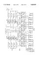
- FIG. 5 shows electrical connections among a plurality, specifically eight, of detectors 22 associated with one of the item processing paths.
- a source 28 of substantially constant electrical current provides a substantially constant electrical current of about 2.0 milliamperes through a relatively reduced temperature reference resistor 30, the detectors 22 and a relatively increased temperature reference resistor 32 which are electrically connected in series.
- the electrical voltage across each resistor 30 or 32 or detector 22 is the product of the current (about 0.002 amperes in an exemplary embodiment) and the resistance (in Ohms) of the detector 22 or resistor 30 or 32. This is an application of the well known formula
- the resistors 30 and 32 are precision resistors of nominal resistances.
- the resistor 30 has a nominal resistance of about 111 Ohms while the resistor 32 has a nominal resistance of about 123 Ohms. Voltages across the resistors 30 and 32 are applied by electrical connections on both sides of the resistors 30 and 32 to all of the source signal selectors 34 in the sensor 16 associated with the appropriate processing path.
- the general construction of an exemplary embodiment of the slave sensor 16 is shown in FIG. 3.
- the sensor 16 contains a plurality, specifically eight, station circuits 36.
- Each of the station circuits 36 includes a source signal selector 34, a prefilter 38, an amplifier 40 and a postfilter 42.
- the source signal selector 34 selectively electrically connects the associated station circuit 36 to one of two reference signals, corresponding to the relatively increased and reduced temperatures, or to the detector 22 associated with a specific heater 18.
- the source signal selector 34 may be a multiplexer.
- the controller 12 determines to which of the two reference signals or the detector 22 the station circuit 36 is connected.
- a specific embodiment of the prefilter 38 is a single pole lowpass filter with a cutoff frequency of about 226 Hertz.
- the amplifier 40 has a gain of about 19.96.
- a specific embodiment of the postfilter 42 is a single pole lowpass filter with a cutoff frequency of about 18 Hertz.
- Each station circuit 36 in a given sensor 16 is electrically connected with a station signal selector 44.
- the station signal selector 44 in an exemplary embodiment, may be a multiplexer.
- the station signal selector 44 selectively electrically connects an output of one of the station circuits 36 to the master sensor 46, illustrated schematically in FIGS. 4A, 4B and 4C. Comparison of FIG. 3 with FIGS. 4A, 4B and 4C illustrates similarities and differences among the slave sensors 16 and the master sensor 46.
- the selective electrical connection performed by the station signal selector 44 is determined by the controller 12.
- the master sensor 46 comprises a channel signal selector 48 which selectively electrically connects the outputs of all station signal selectors 44 to a range selection device 50.
- the channel signal selector 48 may be a multiplexer.
- the range selection device 50 may be a substraction circuit that subtracts one of the two selectable signals from the output of the channel signal selector 48 and amplifies the resulting signal by a factor of about 16.68. Output of the range selection device 50 is applied to a 12-bit analog to digital converter 52 which is electrically connected with the range selection device 50. Output of the converter 52 is electrically connected to the controller 12.
- the embodiment 10 maintains a desired temperature in a processing path within an instrument.
- thermal control is effected in periodic temporal cycles of about 683 msec. In each cycle, the thermal energy associated with the processing path is detected, corresponding data manipulation occurs, and the heaters 18 for that processing path are energized in a manner appropriate to maintain the associated thermal energy at the desired value.
- the routine begins with thermal energy or temperature detection.
- the temperature at each heater 18 is detected by the associated detector 22 and sensor 16.
- a voltage is generated across a detector 22 due to the substantially constant current of about 2.0 milliamperes from the constant current source 28 for the processing path corresponding to the heater 18.
- This voltage is applied to the source signal selector 34.
- the source signal selector 34 monitors voltage across the detector 22 and applies that voltage to an associated prefilter 38.
- the prefilter 38 reduces electrical noise and applies the voltage to the amplifier 40.
- the amplifier 40 amplifies the electrical signal associated with the applied voltage by a factor of about 19.96 and sends the amplified signal through the postfilter 42 which further reduces electrical noise.
- the output of the postfilter 42 is one of the input signals of the station signal selector 44.
- the controller 12 sends an electrical signal (digital) to address inputs of the station signal selector 44 and the channel signal selector 48. Responsive to the signal from the controller 12, the selectors 44 and 48 cause voltage across the desired heater's 18 detector 22 to be sent to the range selection device 50.
- the range selection device 50 subtracts one of two voltages from the channel signal selector 48 output to provide a range, in an exemplary embodiment at least two ranges, of sensor operation.
- a first range is approximately from about 5° Celsius to about 35° Celsius.
- a second range is approximately from about 30° C. to about 60° C.
- the first range is utilized by the routine during the embodiment 10 startup phase.
- the second range is utilized by the routine during an operation control process.
- the subtractor circuit of the range selection device 50 shifts voltage from the detector 22 so that, when at a relatively low end of a selected temperature range (for example, about 5° Celsius during startup or about 30° Celsius during operation), the resulting signal is at about a high end of the analog to digital converter 52 input range (about 10 volts).
- the analog to digital converter 52 converts voltage at its input to a 12 bit digital signal representing the temperature at the relevant heater 18 and sends this 12 bit digital signal to the controller 12.
- the controller 12 compares the 12 bit digital signal representing the temperature at the relevant heater 18 to a 12 bit reference signal, AD -- REF, representing the desired temperature of the related item processing path (T desired ).
- the reference signal is calculated as:
- IG and K are constants for each heater 18 determined during calibration, as described later.
- the numerical difference between the output of the analog to digital converter 52 and AD -- REF is statistically offset by about 8 hexadecimal counts and stored in a memory device as a variable called TMP -- RESULT.
- the controller 12 also contains in suitable memory the values of TMP -- RESULT for the relevant heater 18 that were stored from the previous, about 256, heater cycles.
- the controller 12 multiplies the average value by five and adds the current value of TMP -- RESULT to yield a numerical value RESULT, used to control application of electrical energy to the source 20 for the relevant heater 18.
- the application of electrical energy to the source 20 is controlled by determining the number of half-cycles of electrical energy that will be applied to the source 20.
- the application of a half-cycle of electrical energy is termed a pulse.
- a full heater cycle is defined as about 64 electrical half-cycles, so the maximum amount of electrical energy that could be applied to a given source 20 is about 64 pulses per heater cycle.
- the numerical result of the heater control algorithm determines the number of pulses of electrical energy per heater cycle in accordance with the following table:
- the pulses for a given source 20 are spread out within the cycle to yield an approximately uniform duty cycle for each source 20.
- heaters 18 there are a plurality of heaters 18, each assigned a number from 1 to 8 associated with each of the six processing paths.
- even numbered heaters 18, or the associated sources 20 only receive pulses on even numbered half-cycles
- odd numbered heaters 18, or the associated sources 20 only receive pulses on odd numbered half-cycles, so that no more than about 24 heater sources 20 are energized simultaneously.
- the heater control process is adjusted during the startup period, defined as the first 4 of 5 phases.
- the startup phases last a total of about 30 minutes following energization of the heater control system (about five minutes each for phases 1 through 3, and about fifteen minutes for phase 4).
- Phase 5 constitutes operation.
- phase 1 only the sources 20 for heaters 2 through 4 in each channel may be energized at about full power (about 64 cycles) and the remaining sources 20 are not energized.
- the sources 20 for heaters 2 through 4 may be energized up to about half power (about 32 cycles), stations 5 and 6 may be energized up to about full power, and the other heater 18 sources 20 remain deenergized.
- the sources 20 for heaters 2 through 6 may be energized at up to about half power, the source 20 for heater 7 may be energized at about full power, and the source 20 for heater 8 is not energized.
- the sources 20 for heaters 2 through 8 may be energized at up to about half power.
- the source 20 for heater 1 in this exemplary embodiment is never energized.
- the controller 12 determines which heater sources 20 will be energized for the next electrical half-cycle, and sends this information to the relevant driver latch circuit 26.
- the latch circuit 26 stores this information until the next electrical half-cycle begins.
- the heater control devices 25 sense the beginning of the next electrical half-cycle (a zero crossing in the electrical energy supply voltage) and actuate in accordance with the data stored in the latch circuit 26 so that electrical energy is applied to the proper sources 20 for that electrical half-cycle.
- FIG. 6 a block diagram of the thermal control system is presented in FIG. 6.
- the thermal control system can be calibrated as it operates. Specifically, an "on-the-fly" calibration scheme may be used to automatically correct the thermal control system comprising the embodiment 10 for the effects of thermal irregularities or variances from the desired temperature, such as component aging and drift. In particular, this calibration scheme may be used to correct for long-term changes in the sensor circuits 16.
- the calibration scheme generally detects output (digital) resulting from measuring voltages across resistors 30 and 32 of a particular heater's 18 item processing path.
- the resistors 30 and 32 are assumed to represent the resistances of the detectors 22 for a relatively increased temperature condition (about 123 ⁇ ) and a relatively reduced temperature condition (about 111 ⁇ ).
- the measured digital values are used by numerical algorithms executed by the controller 10.
- the values measured in each calibration remain in effect until the next calibration occurs.
- calibration of the heaters 18 in each item processing path occurs within about 30 minutes. When a calibration cycle is finished, another calibration cycle begins. One heater 18 is calibrated at a time.
- the source 20 for a heater 18 being calibrated is energized in a manor substantially similar to an average history of heater 18 operation during the previous (about eight) heater 18 cycles, as recorded in a history matrix which may reside in a suitable memory.
- the history matrix is not updated during calibration.
- IG [(digital output from measuring about 111 ⁇ resistor)-(digital output from measuring about 123 ⁇ resistor)]/12.0
- K (IG*111.0)+(digital output from measuring about 111 ⁇ resistor)
- Step 1 The heater 18 to be calibrated is electrically disconnected from its detector 20 and is connected to the relatively reduced temperature reference resistor 30 by switching the heater's 18 source signal selector 34. Essentially, the relatively reduced temperature reference resistor 30 takes the place of the detector 22 in the relevant circuit. An average value of the history matrix is read by software when the heater 18 temperature is requested through steps 2-6. The history matrix is not updated during steps 2-6.
- Step 2 The amplifier 40 slews, in about a two second delay period, to the relatively reduced temperature reference value and stabilizes.
- Step 3 An updated relatively reduced temperature reference value is recorded for the heater electronics (FIGS. 3, 4A and 4B) being calibrated.
- Step 4 The control algorithm is updated using the value of the relatively reduced temperature reference reading taken during step 3, by updating K, IG and AD -- REF.
- Step 5 The heater electronics are electrically disconnected from the relatively reduced temperature reference resistor 30 and is electrically connected to the detector 22 by switching the appropriate source signal selector 34. Essentially, the detector 22 has replaced the relatively reduced temperature reference resistor 30 in the relevant circuit.
- Step 6 The amplifier channel 40 to slews, in about a two second delay period, to the value of the heater 18 thermal energy detector 22 and stabilizes.
- Step 7 The algorithm retrieves real time temperature information from the sensor 16, and the history matrix is updated.
- Step 8 All remaining heaters 18 undergo steps 1-7 using an associated relatively reduced temperature reference resistor 30.
- Step 9 Steps 1-8 are repeated using a relatively increased temperature reference resistor 32. Any "out of range” condition on any relatively decreased of increased reference is reported to an operator as an error by the controller 12.
Landscapes
- Physics & Mathematics (AREA)
- General Physics & Mathematics (AREA)
- Engineering & Computer Science (AREA)
- Automation & Control Theory (AREA)
- Control Of Temperature (AREA)
- Control Of Resistance Heating (AREA)
Abstract
Embodiments described herein provide methods and apparatuses for thermally controlling an instrument. According to one embodiment, an apparatus includes a heater and a source of electrical energy electrically connected with the heater for energizing the heater to produce thermal energy. A driver is electrically connected with the heater and the source of electrical energy for controlling application of electrical energy to the heater. A sensor is electrically connected with the heater for detecting thermal energy produced by the heater responsive to the electrical energy from the source of electrical energy. A controller is electrically connected with the driver and the sensor for controlling production of thermal energy by the heater responsive to electrical energy from the source of electrical energy. Another embodiment provides a method in which a heater is electrically connected with a relatively reduced thermal energy reference resistor. An amplifier operatively associated with the heater slews to a relatively reduced thermal energy value which is recorded in memory. An algorithm controlling the heater is updated. The heater is electrically connected with a detector for sensing thermal energy produced by the heater. The amplifier slews to a value associated with the detector.
Description
Embodiments described herein generally relate to an apparatus and a method for controlling temperature. More specifically, the embodiments relate to an apparatus and a method providing thermal control of an element of an analytical instrument.
Analytical instruments are available for performing a number of functions. Some analytical instruments perform medical tests on biological samples, such as human blood and the like. These medical tests may determine if, for example, a human blood sample is infected with the AIDS virus. To perform the medical tests, the analytical instrument may mix the blood sample with another fluid, such as reagents and the like. The blood sample reacts with the added fluid. For some of these reactions between the added fluid and the blood sample to take place as intended, it may be desirable to maintain the blood sample/added fluid mixture at a specific temperature. The mixture may need to be kept at that specific temperature for a predetermined period of time. This time period may be referred to as an "incubation period." Similar concerns about appropriate temperatures for appropriate times may relate to the blood sample and the added fluid separately before mixing.
To keep the blood sample/added fluid mixture at the desired temperature for the desired time period, the analytical instrument may be provided with a heater of sorts. The heater may be positioned near to a vessel holding the blood sample/added fluid mixture. A controller is associated with the heater for insuring that the heater supplies the vessel, and thus the mixture, with sufficient heat energy to keep the mixture at the desired, specific temperature for the desired time.
If the mixture were not kept at the specific temperature for the specific time period, then the analytical instrument may not be able to perform the medical tests as intended. For instance, the instrument may not be able to obtain correct information about the blood sample. Assuming the blood sample were infected with the AIDS virus, if the blood sample/added fluid mixture were not kept at the desired temperature for the desired time period, then the analytical instrument may tell an operator of the instrument that the blood sample is not infected with the AIDS virus. This is undesirable.
Many things may cause the mixture not to be kept at the desired temperature for the desired time period. For instance, the heater may degrade or age over time. The controller may have difficulty in controlling the heater. As the heater ages, the heater may not be able to provide the appropriate heat to the mixture for the proper time period. The heat applied to the mixture by the heater may change or vary over time. Thus, it can be appreciated that it is desirable to provide an apparatus and a method for controlling the heater and the heat applied to the blood sample, added fluid and mixture such that those things are kept at the proper temperature for the proper time period.
Embodiments described herein provide methods and apparatuses for thermally controlling an instrument. According to one embodiment, an apparatus includes a heater and a source of electrical energy electrically connected with the heater for energizing the heater to produce thermal energy. A driver is electrically connected with the heater and the source of electrical energy for controlling application of electrical energy to the heater. A sensor is electrically connected with the heater for detecting thermal energy produced by the heater responsive to the electrical energy from the source of electrical energy. A controller is electrically connected with the driver and the sensor for controlling production of thermal energy by the heater responsive to electrical energy from the source of electrical energy.
Another embodiment provides a method in which a heater is electrically connected with a relatively reduced thermal energy reference resistor. An amplifier operatively associated with the heater slews to a relatively reduced thermal energy value which is recorded in memory. An algorithm controlling the heater is updated. The heater is electrically connected with a detector for sensing thermal energy produced by the heater. The amplifier slews to a value associated with the detector.
In an additional embodiment, a method of thermally controlling an instrument includes electrically connecting a heater with a relatively increased thermal energy reference resistor. An amplifier operatively associated with the heater is allowed to slew to a relatively increased thermal energy value. The relatively increased thermal energy value is recorded in memory. An algorithm controlling the heater is updated. The heater is electrically connected with a detector for sensing thermal energy produced by the heater. The amplifier is allowed to slew to a value associated with the detector.
A further embodiment provides a method of thermally controlling an instrument wherein a heater is energized such that the heater produces thermal energy. At least one of a relatively increased temperature reference value and a relatively reduced temperature reference value is consulted while the heater is energized to calibrate the heater.
Yet another embodiment comprises a method in which a heater is energized with electrical energy to produce thermal energy. A thermal energy level produced by the heater is detected with a detector operatively associated with the heater. The detected thermal energy level is compared with a predetermined thermal energy level. The electrical energy applied to the heater is changed such that the detected thermal energy level is substantially similar to the predetermined thermal energy level.
FIG. 1 is a general schematic block diagram of an apparatus and a method for thermal control;
FIG. 2 is a schematic diagram of a driver comprising the apparatus shown in FIG. 1;
FIG. 3 is a schematic diagram of a slave sensor comprising the apparatus of FIG. 1;
FIGS. 4A, 4B and 4C illustrate schematically a master sensor comprising the apparatus of FIG. 1;
FIG. 5 is a schematic diagram of a circuit comprising part of the apparatus of FIG. 1; and
FIG. 6 is a flow chart illustrating operation of the apparatus and method of FIG. 1.
Embodiments disclosed herein relate to apparatuses and methods providing thermal control. The apparatuses and methods may be utilized in a number of employments. However, for the sake of clarity of understanding, the embodiments will be discussed with respect to their employment with an analytical instrument. For instance, the embodiments may be used with the instruments and methods disclosed in U.S. Pat. Nos 5,006,309, 5,089,424, 5,120,199, 5,185,264, 5,198,368 and 5,244,630. Those patents are assigned to the assignee of the present case and the disclosures thereof are specifically incorporated herein, in their entirety, by this reference. It is to be noted that elements of the disclosed embodiments may be combined in any appropriate fashion to arrive at yet further embodiments. Thus, the scope of the claims is not to be limited to the embodiments disclosed herein. To clarify relations among the apparatuses and the methods, both will be discussed simultaneously.
One embodiment 10 of a thermal control apparatus and method is illustrated in FIG. 1. The embodiment 10 generally comprises a controller 12, a driver 14, a sensor 16, and a heater 18, shown in dotted lines in FIG. 1. The heater 18 comprises a source 20 of thermal energy and a detector 22 that detects thermal energy in the heater 18. The controller 12 is electrically connected with the driver 14 and the sensor 16. The driver 14 is electrically connected with the source 20 of thermal energy. The sensor 16 is electrically connected with the detector 22. A source 24 of electrical energy is electrically connected with the controller 12, the driver 14 and the sensor 16 for supplying those elements with electrical energy.
In an exemplary embodiment, the controller 12 may be a computer having memory and running appropriate routines. As referred to herein, memory may be a RAM, a ROM, an EPROM, a SRAM and the like. In one particular embodiment, the controller 12 comprises a 68HC11 microcontroller available from Motorola (Schaumburg, Ill.). The controller 12 may include a digital logic device and memory that are electrically connected with at least one of the driver 14 and the sensor 16. The controller 12 performs appropriate routines, discussed in detail later, for controlling thermal energy in the heater 18.
The driver 14 generally controls application of electrical energy from the source 24 to the source 20 of thermal energy in the heater 18. Application of electrical energy by the driver 14 to the source 20 is directed by the controller 12. The driver 14 may comprise, in one embodiment, a solid state relay and the like.
The sensor 16 monitors an electrical signal generated by the detector 22 indicative of thermal energy present in the heater 18. The sensor 16 sends a complementary signal to the controller 12 such that the controller 12 is provided with information representing the thermal energy present in the heater 18.
The heater 18, in an exemplary embodiment, may comprise a thermally conductive body, made of a metal such as aluminum and the like, with which the source 20 is operatively associated. The source 20 may be operatively associated with the body through a suitable technique, such as adhesive and the like. The body, in some embodiments, may be constructed to provide at least one of a cover for an item processing path in the instrument, a mechanism for transferring thermal energy from the source 20 to the item being processed, and structural support for instrument components, such as dispensers, washers, aspirators, etc. The body is constructed and positioned to assist in providing the desired temperature for the desired time period to the item being processed, such as a biological sample and the like, by the instrument.
In one embodiment, the source 20 of thermal energy may be an electrical heating element, such as a resistive foil heating element with a nominal resistance of about 232 Ohms and a voltage rating of about 120 Voltsrms. The source 20 may incorporate a thermal energy limiter, such as a self-resetting thermal limit switch and the like. In a specific embodiment, the self-resetting thermal limit switch may interrupt flow of electrical current through the source 20 when the temperature of the switch approaches about 80° Celsius and may reset to again allow current flow through the source 20 when the temperature of the switch approaches about 60° Celsius.
The detector 22, in an exemplary embodiment, is operatively associated with the body through suitable means, such as an adhesive and the like. The detector 22 may be of any construction that provides an electrical signal indicative of the thermal energy associated with the heater 18. In one specific embodiment, the detector 22 may be a SDI-GR2101 resistive temperature detector available from SDI of Attleboro, Mass. This resistive temperature detector has an electrical resistance R (in Ohms) of about
R=100+0.3908.T-5.802×10.sup.-5.T.sup.2
where T is the temperature in degrees Celsius.
To provide greater understanding, a particularly specific embodiment will now be discussed. It is to be noted that the specific details given are for illustration only as do not limit the claims. Like reference numerals are used for similar structures to provide coherency.
A particular embodiment is illustrated in FIGS. 2 through 6. Those Figures show an embodiment which provides thermal control for a plurality of, specifically six, item processing paths in an analytical instrument. At least one of the processing paths may not be thermally controlled as the other paths are controlled. Each processing path includes a plurality of, specifically eight, heaters 18. At least one driver 14 (FIG. 2) and at least one sensor 16 (FIG. 3 or FIGS. 4A, 4B and 4C) are dedicated to each processing path. Thus, one controller 12 is electrically connected with six drivers 14 and six sensors 16. One of the sensors 16 is a master sensor 46 (FIGS. 4A, 4B and 4C) which is discussed in detail later. All other sensors 16 associated with the master sensor 46 are slaves to the master 46. Each of the drivers 14 and sensors 16 are respectively electrically connected with suitable source 20 and detector 22 pairs. There is one source 20 and detector 22 pair for each of the eight heaters 18 along each of the six item processing paths. Each heater 18 comprises a body, a source 20 and a detector 22.
As shown in FIG. 2, each driver 14 contains a plurality, eight in an exemplary embodiment, of control devices 25. The control device 25 may be a solid state relay and the like. In an exemplary embodiment, the control device 25 is an about 140 Volt, about 3 amp, about 50/60 Hertz solid state relay, such as model 70S2-04-B available from Grayhill, Inc. of La Grange, Ill. Each of the control devices 25 is electrically associated with a source 20 and determines application of electrical energy from the source 24 of electrical energy to the associated source 20 of thermal energy.
The driver 14 may comprise a latch circuit 26. The latch circuit 26 may be a data storage device, such as a flip-flop array and the like. The controller 12 sends an electrical signal (digital) to the latch circuit 26. The latch circuit 26 is electrically connected with the control devices 25 such that the control devices 25 determine application of electrical energy from the source 24 of electrical energy to the source 20 of thermal energy responsive to a signal from the controller 12.
FIG. 5 shows electrical connections among a plurality, specifically eight, of detectors 22 associated with one of the item processing paths. A source 28 of substantially constant electrical current provides a substantially constant electrical current of about 2.0 milliamperes through a relatively reduced temperature reference resistor 30, the detectors 22 and a relatively increased temperature reference resistor 32 which are electrically connected in series. The electrical voltage across each resistor 30 or 32 or detector 22 is the product of the current (about 0.002 amperes in an exemplary embodiment) and the resistance (in Ohms) of the detector 22 or resistor 30 or 32. This is an application of the well known formula
Voltage=Current×Resistance.
This voltage is conveyed by electrical connections on both sides of each detector 22 to an associated source signal selector 34 in the appropriate sensor 16 for the particular processing path. In a particular embodiment, the resistors 30 and 32 are precision resistors of nominal resistances. In an exemplary embodiment, the resistor 30 has a nominal resistance of about 111 Ohms while the resistor 32 has a nominal resistance of about 123 Ohms. Voltages across the resistors 30 and 32 are applied by electrical connections on both sides of the resistors 30 and 32 to all of the source signal selectors 34 in the sensor 16 associated with the appropriate processing path.
The general construction of an exemplary embodiment of the slave sensor 16 is shown in FIG. 3. The sensor 16 contains a plurality, specifically eight, station circuits 36. Each of the station circuits 36 includes a source signal selector 34, a prefilter 38, an amplifier 40 and a postfilter 42. The source signal selector 34 selectively electrically connects the associated station circuit 36 to one of two reference signals, corresponding to the relatively increased and reduced temperatures, or to the detector 22 associated with a specific heater 18. In one embodiment, the source signal selector 34 may be a multiplexer. The controller 12 determines to which of the two reference signals or the detector 22 the station circuit 36 is connected. A specific embodiment of the prefilter 38 is a single pole lowpass filter with a cutoff frequency of about 226 Hertz. The amplifier 40 has a gain of about 19.96. A specific embodiment of the postfilter 42 is a single pole lowpass filter with a cutoff frequency of about 18 Hertz.
Each station circuit 36 in a given sensor 16 is electrically connected with a station signal selector 44. The station signal selector 44, in an exemplary embodiment, may be a multiplexer. The station signal selector 44 selectively electrically connects an output of one of the station circuits 36 to the master sensor 46, illustrated schematically in FIGS. 4A, 4B and 4C. Comparison of FIG. 3 with FIGS. 4A, 4B and 4C illustrates similarities and differences among the slave sensors 16 and the master sensor 46. The selective electrical connection performed by the station signal selector 44 is determined by the controller 12. The master sensor 46 comprises a channel signal selector 48 which selectively electrically connects the outputs of all station signal selectors 44 to a range selection device 50. The channel signal selector 48 may be a multiplexer. The range selection device 50 may be a substraction circuit that subtracts one of the two selectable signals from the output of the channel signal selector 48 and amplifies the resulting signal by a factor of about 16.68. Output of the range selection device 50 is applied to a 12-bit analog to digital converter 52 which is electrically connected with the range selection device 50. Output of the converter 52 is electrically connected to the controller 12.
Further details of the embodiments disclosed herein may become clear with reference to the following operational description, which is given as an example only. The embodiment 10 maintains a desired temperature in a processing path within an instrument. In this embodiment, thermal control is effected in periodic temporal cycles of about 683 msec. In each cycle, the thermal energy associated with the processing path is detected, corresponding data manipulation occurs, and the heaters 18 for that processing path are energized in a manner appropriate to maintain the associated thermal energy at the desired value.
All operations are controlled by digital electrical signals from the controller 12 to the other components in the system discussed above. Operation of the controller 12 is governed by an appropriate routine contained in memory available to the embodiment 10. Accordingly, the following example contains references, where appropriate, to portions of a source code, written in C, of the routine which is included at the end of this description and before the claims. Specifically, the following text refers to certain lines in the source code at illustrative locations. When a numbered STEP is encountered in the following text, reference should be made to the relevant portion of the source code, indicated by the same STEP number, to gain a more complete understanding of the routine.
The routine begins with thermal energy or temperature detection. The temperature at each heater 18 is detected by the associated detector 22 and sensor 16. A voltage is generated across a detector 22 due to the substantially constant current of about 2.0 milliamperes from the constant current source 28 for the processing path corresponding to the heater 18. This voltage is applied to the source signal selector 34. During the temperature detection process, the source signal selector 34 monitors voltage across the detector 22 and applies that voltage to an associated prefilter 38. The prefilter 38 reduces electrical noise and applies the voltage to the amplifier 40. The amplifier 40 amplifies the electrical signal associated with the applied voltage by a factor of about 19.96 and sends the amplified signal through the postfilter 42 which further reduces electrical noise. The output of the postfilter 42 is one of the input signals of the station signal selector 44.
The controller 12 sends an electrical signal (digital) to address inputs of the station signal selector 44 and the channel signal selector 48. Responsive to the signal from the controller 12, the selectors 44 and 48 cause voltage across the desired heater's 18 detector 22 to be sent to the range selection device 50. The range selection device 50 subtracts one of two voltages from the channel signal selector 48 output to provide a range, in an exemplary embodiment at least two ranges, of sensor operation.
In an exemplary embodiment, a first range is approximately from about 5° Celsius to about 35° Celsius. A second range is approximately from about 30° C. to about 60° C. The first range is utilized by the routine during the embodiment 10 startup phase. The second range is utilized by the routine during an operation control process. The subtractor circuit of the range selection device 50 shifts voltage from the detector 22 so that, when at a relatively low end of a selected temperature range (for example, about 5° Celsius during startup or about 30° Celsius during operation), the resulting signal is at about a high end of the analog to digital converter 52 input range (about 10 volts).
The analog to digital converter 52 converts voltage at its input to a 12 bit digital signal representing the temperature at the relevant heater 18 and sends this 12 bit digital signal to the controller 12. The controller 12 compares the 12 bit digital signal representing the temperature at the relevant heater 18 to a 12 bit reference signal, AD-- REF, representing the desired temperature of the related item processing path (Tdesired). The reference signal is calculated as:
AD.sub.-- REF=0.5+K-(IG*FIXED)
where
FIXED=100.0+(0.3908*T.sub.desired)-(0.0000580195*T.sub.desired.spsb.2)
and IG and K are constants for each heater 18 determined during calibration, as described later. The numerical difference between the output of the analog to digital converter 52 and AD-- REF is statistically offset by about 8 hexadecimal counts and stored in a memory device as a variable called TMP-- RESULT.
The controller 12 also contains in suitable memory the values of TMP-- RESULT for the relevant heater 18 that were stored from the previous, about 256, heater cycles. The sum of the previous, about 256, TMP-- RESULT values, termed RANDY-- SUM, is divided by a number equal to the previous number, about 256, of heater cycles to yield an average value of TMP-- RESULT for the previous cycles.
The controller 12 multiplies the average value by five and adds the current value of TMP-- RESULT to yield a numerical value RESULT, used to control application of electrical energy to the source 20 for the relevant heater 18.
The application of electrical energy to the source 20 is controlled by determining the number of half-cycles of electrical energy that will be applied to the source 20. The application of a half-cycle of electrical energy is termed a pulse. A full heater cycle is defined as about 64 electrical half-cycles, so the maximum amount of electrical energy that could be applied to a given source 20 is about 64 pulses per heater cycle.
The numerical result of the heater control algorithm (RESULT) determines the number of pulses of electrical energy per heater cycle in accordance with the following table:
______________________________________STEP 5 Numerical Result Pulses per Heater Cycle ______________________________________ 0 or less 1 1 or 2 2 3 or 4 4 5 or 6 8 7 16 8 (or more in normal control) 32 9 or more (only during instrument 64 startup) ______________________________________
The pulses for a given source 20 are spread out within the cycle to yield an approximately uniform duty cycle for each source 20.
In a particular embodiment, there are a plurality of heaters 18, each assigned a number from 1 to 8 associated with each of the six processing paths. During control, in an exemplary embodiment, even numbered heaters 18, or the associated sources 20, only receive pulses on even numbered half-cycles, and odd numbered heaters 18, or the associated sources 20, only receive pulses on odd numbered half-cycles, so that no more than about 24 heater sources 20 are energized simultaneously.
The heater control process is adjusted during the startup period, defined as the first 4 of 5 phases. The startup phases last a total of about 30 minutes following energization of the heater control system (about five minutes each for phases 1 through 3, and about fifteen minutes for phase 4). Phase 5 constitutes operation. During phase 1, only the sources 20 for heaters 2 through 4 in each channel may be energized at about full power (about 64 cycles) and the remaining sources 20 are not energized. During phase 2, the sources 20 for heaters 2 through 4 may be energized up to about half power (about 32 cycles), stations 5 and 6 may be energized up to about full power, and the other heater 18 sources 20 remain deenergized. During phase 3, the sources 20 for heaters 2 through 6 may be energized at up to about half power, the source 20 for heater 7 may be energized at about full power, and the source 20 for heater 8 is not energized. During phase 4 (as in operation phase 5), the sources 20 for heaters 2 through 8 may be energized at up to about half power. The source 20 for heater 1 in this exemplary embodiment is never energized.
Referring to FIG. 2, the controller 12 determines which heater sources 20 will be energized for the next electrical half-cycle, and sends this information to the relevant driver latch circuit 26. The latch circuit 26 stores this information until the next electrical half-cycle begins. The heater control devices 25 sense the beginning of the next electrical half-cycle (a zero crossing in the electrical energy supply voltage) and actuate in accordance with the data stored in the latch circuit 26 so that electrical energy is applied to the proper sources 20 for that electrical half-cycle.
To further illustrate, a block diagram of the thermal control system is presented in FIG. 6.
The thermal control system can be calibrated as it operates. Specifically, an "on-the-fly" calibration scheme may be used to automatically correct the thermal control system comprising the embodiment 10 for the effects of thermal irregularities or variances from the desired temperature, such as component aging and drift. In particular, this calibration scheme may be used to correct for long-term changes in the sensor circuits 16.
The calibration scheme generally detects output (digital) resulting from measuring voltages across resistors 30 and 32 of a particular heater's 18 item processing path. The resistors 30 and 32 are assumed to represent the resistances of the detectors 22 for a relatively increased temperature condition (about 123 Ω) and a relatively reduced temperature condition (about 111 Ω). The measured digital values are used by numerical algorithms executed by the controller 10. The values measured in each calibration remain in effect until the next calibration occurs. In an exemplary embodiment, calibration of the heaters 18 in each item processing path occurs within about 30 minutes. When a calibration cycle is finished, another calibration cycle begins. One heater 18 is calibrated at a time. During calibration, the source 20 for a heater 18 being calibrated is energized in a manor substantially similar to an average history of heater 18 operation during the previous (about eight) heater 18 cycles, as recorded in a history matrix which may reside in a suitable memory. The history matrix is not updated during calibration.
Two values for each heater 18 used by the controller 12 and determined during calibration are:
IG=[(digital output from measuring about 111 Ω resistor)-(digital output from measuring about 123 Ω resistor)]/12.0
and
K=(IG*111.0)+(digital output from measuring about 111 Ω resistor)
A sequence of steps during calibration is as follows (referring to all of the Figures):
Step 1: The heater 18 to be calibrated is electrically disconnected from its detector 20 and is connected to the relatively reduced temperature reference resistor 30 by switching the heater's 18 source signal selector 34. Essentially, the relatively reduced temperature reference resistor 30 takes the place of the detector 22 in the relevant circuit. An average value of the history matrix is read by software when the heater 18 temperature is requested through steps 2-6. The history matrix is not updated during steps 2-6.
Step 2: The amplifier 40 slews, in about a two second delay period, to the relatively reduced temperature reference value and stabilizes.
Step 3: An updated relatively reduced temperature reference value is recorded for the heater electronics (FIGS. 3, 4A and 4B) being calibrated.
Step 4: The control algorithm is updated using the value of the relatively reduced temperature reference reading taken during step 3, by updating K, IG and AD-- REF.
Step 5: The heater electronics are electrically disconnected from the relatively reduced temperature reference resistor 30 and is electrically connected to the detector 22 by switching the appropriate source signal selector 34. Essentially, the detector 22 has replaced the relatively reduced temperature reference resistor 30 in the relevant circuit.
Step 6: The amplifier channel 40 to slews, in about a two second delay period, to the value of the heater 18 thermal energy detector 22 and stabilizes.
Step 7: The algorithm retrieves real time temperature information from the sensor 16, and the history matrix is updated.
Step 8: All remaining heaters 18 undergo steps 1-7 using an associated relatively reduced temperature reference resistor 30.
Step 9: Steps 1-8 are repeated using a relatively increased temperature reference resistor 32. Any "out of range" condition on any relatively decreased of increased reference is reported to an operator as an error by the controller 12.
The above discussion shows how the apparatus and method described herein is able to self-calibrate during operation. The apparatus and method do not need to be shut down or interrupted for calibration. ##SPC1##
Claims (6)
1. A method of thermally controlling an instrument including a heater while the heater is in continuous operation, the method comprising the steps of:
(a) electrically connecting a heater with a relatively reduced thermal energy reference resistor;
(b) allowing an amplifier operatively associated with the heater to slew to a relatively reduced thermal energy value;
(c) recording the relatively reduced thermal energy value in memory;
(d) updating an algorithm controlling the heater based on the relatively reduced thermal energy value;
(e) electrically connecting the heater with a detector for sensing thermal energy produced by the heater;
(f) allowing the amplifier to slew to a value associated with the detector;
(g) updating an algorithm controlling the heater based on the value associated with the detector; and
(h) applying electrical energy to the heater based on the relatively reduced thermal energy value and the value associated with the detector.
2. A method as defined in claim 1 further comprising the step of:
(i) repeating steps (a) through (h).
3. A method as defined in claim 1 further comprising the step of:
(i) signaling heater status to an operator.
4. A method of thermally controlling an instrument including a heater while the heater is in continuous operation, the method comprising the steps of:
(a) electrically connecting a heater with a relatively increased thermal energy reference resistor;
(b) allowing an amplifier operatively associated with the heater to slew to a relatively increased thermal energy value;
(c) recording the relatively increased thermal energy value in memory;
(d) updating an algorithm controlling the heater based on the relatively increased thermal energy value;
(e) electrically connecting the heater with a detector for sensing thermal energy produced by the heater;
(f) allowing the amplifier to slew to a value associated with the detector;
(g) updating an algorithm controlling the heater based on the value associated with the detector; and
(h) applying electrical energy to the heater based on the relatively increased thermal energy value and the value associated with the detector.
5. A method as defined in claim 4 further comprising the step of:
(i) repeating steps (a) through (h).
6. A method as defined in claim 4 further comprising the step of:
(i) signaling heater status to an operator.
Priority Applications (5)
| Application Number | Priority Date | Filing Date | Title |
|---|---|---|---|
| US08/322,666 US5628929A (en) | 1994-10-13 | 1994-10-13 | Thermal control apparatus and method |
| PCT/US1995/013144 WO1996012219A1 (en) | 1994-10-13 | 1995-10-06 | Thermal control apparatus and method |
| JP51338396A JP3147170B2 (en) | 1994-10-13 | 1995-10-06 | Thermal control method |
| EP95936869A EP0786105A1 (en) | 1994-10-13 | 1995-10-06 | Thermal control apparatus and method |
| CA002198469A CA2198469C (en) | 1994-10-13 | 1995-10-06 | Thermal control apparatus and method |
Applications Claiming Priority (1)
| Application Number | Priority Date | Filing Date | Title |
|---|---|---|---|
| US08/322,666 US5628929A (en) | 1994-10-13 | 1994-10-13 | Thermal control apparatus and method |
Publications (1)
| Publication Number | Publication Date |
|---|---|
| US5628929A true US5628929A (en) | 1997-05-13 |
Family
ID=23255888
Family Applications (1)
| Application Number | Title | Priority Date | Filing Date |
|---|---|---|---|
| US08/322,666 Expired - Fee Related US5628929A (en) | 1994-10-13 | 1994-10-13 | Thermal control apparatus and method |
Country Status (5)
| Country | Link |
|---|---|
| US (1) | US5628929A (en) |
| EP (1) | EP0786105A1 (en) |
| JP (1) | JP3147170B2 (en) |
| CA (1) | CA2198469C (en) |
| WO (1) | WO1996012219A1 (en) |
Cited By (7)
| Publication number | Priority date | Publication date | Assignee | Title |
|---|---|---|---|---|
| US20040200260A1 (en) * | 2003-04-08 | 2004-10-14 | Klosterman Kurt M. | Apparatus and method for verifying the volume of liquid dispensed by a liquid-dispensing mechanism |
| US20060262827A1 (en) * | 2005-05-23 | 2006-11-23 | Etron Technology, Inc. | Precise temperature sensor with smart programmable calibration |
| US8078333B2 (en) | 2007-07-05 | 2011-12-13 | Baxter International Inc. | Dialysis fluid heating algorithms |
| US20120232716A1 (en) * | 2005-12-16 | 2012-09-13 | Round Rock Research, Llc | System and method for providing temperature data from a memory device having a temperature sensor |
| US20130327842A1 (en) * | 2011-01-28 | 2013-12-12 | Websato SE | Electric heating, vehicle comprising an electric heating as well as method for controlling an electric heating |
| US20180087968A1 (en) * | 2016-09-27 | 2018-03-29 | Topcon Corporation | Temperature measurement device and temperature measurement method |
| US11654221B2 (en) | 2003-11-05 | 2023-05-23 | Baxter International Inc. | Dialysis system having inductive heating |
Families Citing this family (1)
| Publication number | Priority date | Publication date | Assignee | Title |
|---|---|---|---|---|
| JP7541841B2 (en) * | 2020-03-18 | 2024-08-29 | 株式会社Kelk | Temperature Control System |
Citations (11)
| Publication number | Priority date | Publication date | Assignee | Title |
|---|---|---|---|---|
| US3699800A (en) * | 1971-03-04 | 1972-10-24 | King Nutronics Corp | Temperature calibration system |
| US3890836A (en) * | 1973-10-15 | 1975-06-24 | Draf Tool Co Inc | Automatic temperature control system analyzer |
| FR2319154A1 (en) * | 1975-07-22 | 1977-02-18 | Baxter Laboratories Inc | TEMPERATURE-CONTROLLED CHEMICAL TREATMENT EQUIPMENT |
| US4041382A (en) * | 1976-08-16 | 1977-08-09 | The Sippican Corporation | Calibrating a measurement system including bridge circuit |
| US4209837A (en) * | 1978-07-03 | 1980-06-24 | Beckman Instruments, Inc. | Programmable controller |
| US4315413A (en) * | 1979-12-31 | 1982-02-16 | Whirlpool Corporation | Selective temperature control system |
| US4761539A (en) * | 1987-04-13 | 1988-08-02 | The Tappan Company | Oven calibration system having variable stored calibration value |
| US4891497A (en) * | 1988-04-02 | 1990-01-02 | Hakko Metal Industries Limited | Soldering iron temperature regulator |
| US4901257A (en) * | 1987-06-12 | 1990-02-13 | King Nutronics Corporation | Temperature calibration system |
| GB2254452A (en) * | 1991-04-04 | 1992-10-07 | Total Temperature Control Limi | Control of refrigerators and freezers |
| EP0670481A1 (en) * | 1994-01-05 | 1995-09-06 | Becton, Dickinson and Company | Continuously calibrating temperature controller |
Family Cites Families (6)
| Publication number | Priority date | Publication date | Assignee | Title |
|---|---|---|---|---|
| JPH087634B2 (en) * | 1986-12-10 | 1996-01-29 | 日本電熱株式会社 | Temperature control device |
| JPS63171803U (en) * | 1987-04-28 | 1988-11-08 | ||
| JPH0283451A (en) * | 1988-09-21 | 1990-03-23 | Hitachi Ltd | Reactor temperature control device and method for automatic analyzer |
| JP2732270B2 (en) * | 1988-11-22 | 1998-03-25 | 大倉電気株式会社 | Temperature control method |
| JPH05188823A (en) * | 1991-03-08 | 1993-07-30 | Ricoh Co Ltd | Fixing device |
| JPH06281655A (en) * | 1993-03-25 | 1994-10-07 | Olympus Optical Co Ltd | Automatic analyzer |
-
1994
- 1994-10-13 US US08/322,666 patent/US5628929A/en not_active Expired - Fee Related
-
1995
- 1995-10-06 WO PCT/US1995/013144 patent/WO1996012219A1/en not_active Ceased
- 1995-10-06 CA CA002198469A patent/CA2198469C/en not_active Expired - Fee Related
- 1995-10-06 JP JP51338396A patent/JP3147170B2/en not_active Expired - Fee Related
- 1995-10-06 EP EP95936869A patent/EP0786105A1/en not_active Ceased
Patent Citations (11)
| Publication number | Priority date | Publication date | Assignee | Title |
|---|---|---|---|---|
| US3699800A (en) * | 1971-03-04 | 1972-10-24 | King Nutronics Corp | Temperature calibration system |
| US3890836A (en) * | 1973-10-15 | 1975-06-24 | Draf Tool Co Inc | Automatic temperature control system analyzer |
| FR2319154A1 (en) * | 1975-07-22 | 1977-02-18 | Baxter Laboratories Inc | TEMPERATURE-CONTROLLED CHEMICAL TREATMENT EQUIPMENT |
| US4041382A (en) * | 1976-08-16 | 1977-08-09 | The Sippican Corporation | Calibrating a measurement system including bridge circuit |
| US4209837A (en) * | 1978-07-03 | 1980-06-24 | Beckman Instruments, Inc. | Programmable controller |
| US4315413A (en) * | 1979-12-31 | 1982-02-16 | Whirlpool Corporation | Selective temperature control system |
| US4761539A (en) * | 1987-04-13 | 1988-08-02 | The Tappan Company | Oven calibration system having variable stored calibration value |
| US4901257A (en) * | 1987-06-12 | 1990-02-13 | King Nutronics Corporation | Temperature calibration system |
| US4891497A (en) * | 1988-04-02 | 1990-01-02 | Hakko Metal Industries Limited | Soldering iron temperature regulator |
| GB2254452A (en) * | 1991-04-04 | 1992-10-07 | Total Temperature Control Limi | Control of refrigerators and freezers |
| EP0670481A1 (en) * | 1994-01-05 | 1995-09-06 | Becton, Dickinson and Company | Continuously calibrating temperature controller |
Cited By (14)
| Publication number | Priority date | Publication date | Assignee | Title |
|---|---|---|---|---|
| US7114368B2 (en) | 2003-04-08 | 2006-10-03 | Abbott Laboratories | Apparatus and method for verifying the volume of liquid dispensed by a liquid-dispensing mechanism |
| US20060272387A1 (en) * | 2003-04-08 | 2006-12-07 | Klosterman Kurt M | Apparatus and method for verifying the volume of liquid dispensed by a liquid-dispensing mechanism |
| US20040200260A1 (en) * | 2003-04-08 | 2004-10-14 | Klosterman Kurt M. | Apparatus and method for verifying the volume of liquid dispensed by a liquid-dispensing mechanism |
| US8434345B2 (en) | 2003-04-08 | 2013-05-07 | Abbott Laboratories | Apparatus and method for verifying the volume of liquid dispensed by a liquid-dispensing mechanism |
| US11654221B2 (en) | 2003-11-05 | 2023-05-23 | Baxter International Inc. | Dialysis system having inductive heating |
| US20060262827A1 (en) * | 2005-05-23 | 2006-11-23 | Etron Technology, Inc. | Precise temperature sensor with smart programmable calibration |
| US7204638B2 (en) * | 2005-05-23 | 2007-04-17 | Etron Technology, Inc. | Precise temperature sensor with smart programmable calibration |
| CN100359302C (en) * | 2005-05-23 | 2008-01-02 | 钰创科技股份有限公司 | Accurate temperature sensor with automatic programmable calibration |
| US20120232716A1 (en) * | 2005-12-16 | 2012-09-13 | Round Rock Research, Llc | System and method for providing temperature data from a memory device having a temperature sensor |
| US8078333B2 (en) | 2007-07-05 | 2011-12-13 | Baxter International Inc. | Dialysis fluid heating algorithms |
| US9694649B2 (en) * | 2011-01-28 | 2017-07-04 | Webasto SE | Electric heating, vehicle comprising an electric heating as well as method for controlling an electric heating |
| US20130327842A1 (en) * | 2011-01-28 | 2013-12-12 | Websato SE | Electric heating, vehicle comprising an electric heating as well as method for controlling an electric heating |
| US20180087968A1 (en) * | 2016-09-27 | 2018-03-29 | Topcon Corporation | Temperature measurement device and temperature measurement method |
| US10502630B2 (en) * | 2016-09-27 | 2019-12-10 | Topcon Corporation | Temperature measurement device and temperature measurement method |
Also Published As
| Publication number | Publication date |
|---|---|
| EP0786105A1 (en) | 1997-07-30 |
| JPH10509818A (en) | 1998-09-22 |
| CA2198469A1 (en) | 1996-04-25 |
| JP3147170B2 (en) | 2001-03-19 |
| WO1996012219A1 (en) | 1996-04-25 |
| CA2198469C (en) | 2001-12-25 |
Similar Documents
| Publication | Publication Date | Title |
|---|---|---|
| US5521850A (en) | Method and apparatus for calibration and controlling multiple heaters | |
| US6459335B1 (en) | Auto-calibration circuit to minimize input offset voltage in an integrated circuit analog input device | |
| US5628929A (en) | Thermal control apparatus and method | |
| JP2593059B2 (en) | Measurement system for performing continuous calibration and operation method thereof | |
| US5552998A (en) | Method and apparatus for calibration and controlling multiple heaters | |
| EP0572204B1 (en) | Method and apparatus for automated sensor diagnosis | |
| US5469071A (en) | Resistor sensor input apparatus | |
| EP3093659B1 (en) | Thermal conductivity detector and method for operating the same | |
| KR940000675B1 (en) | Device for controlling and calibrating electrical signal | |
| EP0392746A2 (en) | Transducer temperature compensation circuit | |
| US6112162A (en) | Weight measuring apparatus using a plurality of sensors | |
| SE439548B (en) | METHOD OF DETERMINING THE OXYGEN PARTIAL PRESSURE IN A MEDIUM FOR COMPENSATING OPERATION OF THE OXYGLE ELECTRODE AND DEVICE FOR PERFORMING THE PROCEDURE | |
| US20050052274A1 (en) | Resistive temperature device (RTD) module with improved noise immunity | |
| EP0301736B1 (en) | Input-output device | |
| US5724035A (en) | Method of correcting signals for encoder and apparatus for same | |
| JPH0426091A (en) | Heater breakage detection device for multiple point temperature regulator | |
| US4921582A (en) | Dissolved oxygen measuring method | |
| CN107422061B (en) | Thermal Conductivity Detectors and Gas Chromatographs | |
| US20010003922A1 (en) | Arrangement and method for measuring the flow velocity of a gas | |
| JPS60110006A (en) | Multi-range controller | |
| JP3849265B2 (en) | Odor measuring device | |
| JP3425638B2 (en) | Measuring method and measuring element | |
| JPH01229596A (en) | Digital controller | |
| US5097199A (en) | Voltage controlled current source | |
| JP2692135B2 (en) | Load control device |
Legal Events
| Date | Code | Title | Description |
|---|---|---|---|
| AS | Assignment |
Owner name: ABBOTT LABORATORIES, ILLINOIS Free format text: ASSIGNMENT OF ASSIGNORS INTEREST;ASSIGNOR:KLOSTERMAN, KURT;REEL/FRAME:007579/0281 Effective date: 19941013 |
|
| FPAY | Fee payment |
Year of fee payment: 4 |
|
| REMI | Maintenance fee reminder mailed | ||
| LAPS | Lapse for failure to pay maintenance fees | ||
| STCH | Information on status: patent discontinuation |
Free format text: PATENT EXPIRED DUE TO NONPAYMENT OF MAINTENANCE FEES UNDER 37 CFR 1.362 |
|
| FP | Lapsed due to failure to pay maintenance fee |
Effective date: 20050513 |