US5615894A - Shaft seal ring and a method and a device of manufacturing same - Google Patents
Shaft seal ring and a method and a device of manufacturing same Download PDFInfo
- Publication number
- US5615894A US5615894A US08/588,668 US58866896A US5615894A US 5615894 A US5615894 A US 5615894A US 58866896 A US58866896 A US 58866896A US 5615894 A US5615894 A US 5615894A
- Authority
- US
- United States
- Prior art keywords
- lip
- sealing lip
- shaft
- seal ring
- embossed
- Prior art date
- Legal status (The legal status is an assumption and is not a legal conclusion. Google has not performed a legal analysis and makes no representation as to the accuracy of the status listed.)
- Expired - Fee Related
Links
Images

Classifications
-
- F—MECHANICAL ENGINEERING; LIGHTING; HEATING; WEAPONS; BLASTING
- F16—ENGINEERING ELEMENTS AND UNITS; GENERAL MEASURES FOR PRODUCING AND MAINTAINING EFFECTIVE FUNCTIONING OF MACHINES OR INSTALLATIONS; THERMAL INSULATION IN GENERAL
- F16J—PISTONS; CYLINDERS; SEALINGS
- F16J15/00—Sealings
- F16J15/16—Sealings between relatively-moving surfaces
- F16J15/32—Sealings between relatively-moving surfaces with elastic sealings, e.g. O-rings
- F16J15/3244—Sealings between relatively-moving surfaces with elastic sealings, e.g. O-rings with hydrodynamic pumping action
-
- B—PERFORMING OPERATIONS; TRANSPORTING
- B29—WORKING OF PLASTICS; WORKING OF SUBSTANCES IN A PLASTIC STATE IN GENERAL
- B29C—SHAPING OR JOINING OF PLASTICS; SHAPING OF MATERIAL IN A PLASTIC STATE, NOT OTHERWISE PROVIDED FOR; AFTER-TREATMENT OF THE SHAPED PRODUCTS, e.g. REPAIRING
- B29C59/00—Surface shaping of articles, e.g. embossing; Apparatus therefor
- B29C59/02—Surface shaping of articles, e.g. embossing; Apparatus therefor by mechanical means, e.g. pressing
-
- B—PERFORMING OPERATIONS; TRANSPORTING
- B29—WORKING OF PLASTICS; WORKING OF SUBSTANCES IN A PLASTIC STATE IN GENERAL
- B29D—PRODUCING PARTICULAR ARTICLES FROM PLASTICS OR FROM SUBSTANCES IN A PLASTIC STATE
- B29D99/00—Subject matter not provided for in other groups of this subclass
- B29D99/0053—Producing sealings
-
- F—MECHANICAL ENGINEERING; LIGHTING; HEATING; WEAPONS; BLASTING
- F16—ENGINEERING ELEMENTS AND UNITS; GENERAL MEASURES FOR PRODUCING AND MAINTAINING EFFECTIVE FUNCTIONING OF MACHINES OR INSTALLATIONS; THERMAL INSULATION IN GENERAL
- F16J—PISTONS; CYLINDERS; SEALINGS
- F16J15/00—Sealings
- F16J15/16—Sealings between relatively-moving surfaces
- F16J15/32—Sealings between relatively-moving surfaces with elastic sealings, e.g. O-rings
- F16J15/3204—Sealings between relatively-moving surfaces with elastic sealings, e.g. O-rings with at least one lip
- F16J15/3228—Sealings between relatively-moving surfaces with elastic sealings, e.g. O-rings with at least one lip formed by deforming a flat ring
-
- B—PERFORMING OPERATIONS; TRANSPORTING
- B29—WORKING OF PLASTICS; WORKING OF SUBSTANCES IN A PLASTIC STATE IN GENERAL
- B29K—INDEXING SCHEME ASSOCIATED WITH SUBCLASSES B29B, B29C OR B29D, RELATING TO MOULDING MATERIALS OR TO MATERIALS FOR MOULDS, REINFORCEMENTS, FILLERS OR PREFORMED PARTS, e.g. INSERTS
- B29K2027/00—Use of polyvinylhalogenides or derivatives thereof as moulding material
- B29K2027/12—Use of polyvinylhalogenides or derivatives thereof as moulding material containing fluorine
- B29K2027/18—PTFE, i.e. polytetrafluoroethylene, e.g. ePTFE, i.e. expanded polytetrafluoroethylene
-
- B—PERFORMING OPERATIONS; TRANSPORTING
- B29—WORKING OF PLASTICS; WORKING OF SUBSTANCES IN A PLASTIC STATE IN GENERAL
- B29L—INDEXING SCHEME ASSOCIATED WITH SUBCLASS B29C, RELATING TO PARTICULAR ARTICLES
- B29L2031/00—Other particular articles
- B29L2031/26—Sealing devices, e.g. packaging for pistons or pipe joints
-
- F—MECHANICAL ENGINEERING; LIGHTING; HEATING; WEAPONS; BLASTING
- F05—INDEXING SCHEMES RELATING TO ENGINES OR PUMPS IN VARIOUS SUBCLASSES OF CLASSES F01-F04
- F05C—INDEXING SCHEME RELATING TO MATERIALS, MATERIAL PROPERTIES OR MATERIAL CHARACTERISTICS FOR MACHINES, ENGINES OR PUMPS OTHER THAN NON-POSITIVE-DISPLACEMENT MACHINES OR ENGINES
- F05C2225/00—Synthetic polymers, e.g. plastics; Rubber
- F05C2225/04—PTFE [PolyTetraFluorEthylene]
-
- Y—GENERAL TAGGING OF NEW TECHNOLOGICAL DEVELOPMENTS; GENERAL TAGGING OF CROSS-SECTIONAL TECHNOLOGIES SPANNING OVER SEVERAL SECTIONS OF THE IPC; TECHNICAL SUBJECTS COVERED BY FORMER USPC CROSS-REFERENCE ART COLLECTIONS [XRACs] AND DIGESTS
- Y10—TECHNICAL SUBJECTS COVERED BY FORMER USPC
- Y10S—TECHNICAL SUBJECTS COVERED BY FORMER USPC CROSS-REFERENCE ART COLLECTIONS [XRACs] AND DIGESTS
- Y10S277/00—Seal for a joint or juncture
- Y10S277/924—Deformation, material removal, or molding for manufacture of seal
Definitions
- the present invention refers to a shaft seal ring formed of a polytetrafluoroethylene (PTFE) compound or of a material which is similar with regard to the sealing behaviour or durability, comprising a sealing lip and a protective lip integrally formed therewith, as well as to a method and a device of manufacturing a shaft seal ring of that kind.
- PTFE polytetrafluoroethylene
- the recesses are embossed by a separate embossing tool into a seal wafer cut from a PTFE compound tube.
- the wafer is subsequently brought into final shape with a final embossing tool.
- a shaft seal ring of the above-mentioned kind is also known from DE 33 27 229 A1 in which a protective lip integrally formed with the sealing lip is first peeled out of the PTFE compound on the front side of a plate. After forming a recess into the front side of the sealing lip adjacent the protective lip, cuts are made in the radial and in the axial direction. These cuts increase the flexibility of the seal and generate a return flow effect of the oil away from the sealing edge.
- a shaft seal ring made of a PTFE compound is known from DE 36 07 662 A1 wherein the flexibility of the sealing lip is increased by cuts made on the two sides of the sealing lip the cuts are offset with respect to one another by half of the cut distance.
- the object of the invention is to provide an easy to manufacture shaft seal ring of the above-mentioned kind as well as a method and a device of manufacturing the same, by means of which an increased sealing function and dust repelling function in a one-piece sealing element can be achieved.
- the invention includes a seal lip with wavy recesses which can have the shape of one-threaded or multiple threaded helical grooves.
- the wavy recesses are embossed through the protective lip down to the sealing lip at least on the front side of the shaft seal ring, with the sealing lip portion facing the shaft.
- An embodiment is preferred in which the wavy recesses are completely embossed through the seal wafer in such a manner that constant bending flexibility is provided so the sealing lip as well as to the protective lip across the longitudinal extensions thereof.
- An embodiment is preferred in which the wavy recesses are offset on the rear side to the recesses on the front side in such a manner that a wave trough opposes a wave crest.
- An approximately constant wall thickness across the length of the sealing lip or protective lip is achieved thereby, which is responsible for a constant bending stress of the shaft seal ring during operation.
- the method according to the invention requires a minimum of working steps.
- the shaft seal ring is brought to its final shape by embossing the wavy recesses.
- a further shaping step that requires a further embossing shape is not necessary.
- the spreader ring is made of a solid material having lubrication properties and melting at an operating temperature of the shaft seal ring, as can be derived from DE 43 24 529 C1.
- a device for manufacturing a shaft seal ring according to the invention is very simple. It is necessary for this device that at least the one formed part facing the front side of the PTFE-plate or seal wafer is provided with the wavy recesses in negative contour, wherein the formed part facing the rear side of the plate or wafer can be smooth. It is ensured thereby that the wavy recesses are embossed through the protective lip down to the front side of the sealing lip to guarantee the formation of wavy recesses on the side of the sealing lip facing the shaft.
- the other formed part facing the rear side is provided with the wavy recesses, which are preferrably displaced radially offset with respect to the one formed part. This guarantees a complete embossing through all effective areas of the shaft seal ring.
- the wavy recesses create a hydrodynamic return flow effect, wherein a conveying effect in the counter direction of the conveying effect of the wavy recesses on the front side of the sealing lip is achieved on the rear side of the protective lip opposite the other formed part.
- the sealing lip has a conveying effect in the direction of the oil side of the shaft seal ring to be sealed
- the protective lip convey outwardly towards the air side of the seal and thereby ensures an additional dynamic sealing effect against dust entering from the air side.
- the PTFE compound materials for the protective lip on one side and the sealing lip on the other side can be different. In practical application this can be achieved in that the seal wafer is cut of two tubes inserted into each other which have differently defined PTFE compounds, the tubes being fixedly connected to one another during a sintering process. This enables an optimization of the sealing and wear behaviour of the shaft seal ring because the front side of the sealing lip engaging the shaft is formed of a PTFE compound especially adapted to the preconditions of operation during oil lubrication and the protective lip is formed of a different PTFE compound especially adapted to the preconditions of the dry run of the protective lip.
- a holding member for the shaft seal ring can be found of an inexpensive PTFE compound, which does not have to fulfill the high sealing and wear requirements in the contact region of the seal ring.
- a layer of an elastomeric material can be provided in the region of the outer diameter of the shaft seal ring in order to hold the shaft seal ring, the layers serving as a seat in a carrier body or as a housing.
- the bonding of a sealing element made of PTFE by an elastomeric material vulcanized to a metallic carrier body is known from DE 33 09 538 C2.
- the elastomeric material that is required for the bond between the shaft seal ring and the metal of a carrier body, provides a partially or fully rubber covered region at the outer periphery of the shaft seal ring and forms a seat for the shaft seal ring in a housing.
- the geometry of the recesses embossed through the shaft seal ring according to the invention can be varied in accordance with the purposes of application of the shaft seal ring.
- the geometry can be adapted to the objects of sealing fluids of high or low viscosity or for reducing the air suction below the sealing edge.
- a transverse web is provided at the air end of the abutting sealing lip in the recess or in any recess, the transverse web serving as a bulkhead in particular for the static sealing when the shaft is standing still.
- the transverse web or the transverse webs prevent any medium from reaching and from draining in an area outside the sealing lip through the recesses preferrably provided in the shape of one-threaded or multiple threaded threads. It is furthermore ensured by this measure that the area of the sealing lip abutting the shaft is constantly wetted with the medium to be sealed and that a dry run of the sealing lip is excluded thereby.
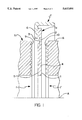
- FIG. 1 is a view of the manufacture of a shaft seal ring according to the invention with a device according to the invention
- FIG. 2 is a partial axial view through a half of a shaft seal ring according to the invention in assembled condition
- FIG. 3 is a modified shaft seal ring according to the invention in a view as in FIG. 2.
- FIG. 1 a blank for a shaft seal ring is indicated by reference numeral 1.
- This blank is in the form of a plate or wafer made of a PTFE compound, which is cut off a tube. Furthermore, a cut is made along line 2 so that a protective lip portion 3 is peeled from the plate 1 and is thus separated from a sealing lip portion 4. This sealing lip portion protrudes radially over the inner end of the protective lip portion towards the interior of the seal ring.
- the annular plate 1 on the protective lip side 5 of the blank is adhered to the radial flange 6' of a metallic carrier body 6 or is connected in a different manner.
- the blank 1 designed in this manner is inserted into a mold having left and right formed parts 7, 8.
- the formed parts 7, 8 are movable parallel to the axis A against the blank 1 in the directions of arrows f, f'.
- the formed parts 7,8 have wavy recesses on their sides facing the blank 1.
- the recesses have the shape of threaded grooves 9, 10 of different profiles.
- the threaded grooves (one-threaded or multiple threaded) of the formed part 7 are inclined with regard to the axial direction, whereas the threaded grooves 10 of the formed part 8 are oriented parallel to the axis a in depth direction and are radially such a manner that the crests of the threaded grooves 9 seen in the axial direction approximately oppose the troughs of the threaded grooves 10.
- the recesses 9, 10 serve for embossing respective wavy recesses into the front side 5 and the rear side 11 of the blank 1, by driving the two formed parts 7, 8 in the axial direction (f, f') against the blank 1.
- the formed parts are punched into the blank for embossing the respective recesses.
- contours of the recesses 9, 10, as shown in FIG. 1 can also be provided laterally reversed.
- a radial displacement of the recesses is preferred in a manner that the wall thickness of the plate 1 is basically equal over the radial extensions thereof.
- FIG. 2 shows a shaft seal ring 20, which is manufactured according to FIG. 1 and which is mounted on the periphery 21 of a shaft 22.
- the protective lip 23 is spread in the direction toward the air side away from the sealing lip 24, which is bent backwards towards the oil side "a". Sealing lip 24 is pressed to the shaft with the front sealing section 25 corresponding to the front side 5 thereof according to FIG. 1. It is evident that owing to the offset of the recesses 9, 10 of the formed parts 7, 8 the cross-sections of the lips 23, 24 are provided with complementary or matching wavy, embossed recesses 32 to 35 and have a constant cross section over the length thereof and thus have approximately constant flexibility.
- the "inverse" complementary recesses 33 provided on the rear side 26 of the protective lip 23 convey or pump in the direction of the air side "i"
- the recesses provided on the front side 27 of the sealing lip 24 convey or pump in the direction of the oil side "a” of the seal. This suprisingly improves the dust-repelling as well as oil returning effect of the shaft seal ring 20.
- FIG. 3 shows two modifications of the shaft seal ring manufactured in the same manner as in FIG. 2.
- the metallic carrier body 6 having a radial flange 6' is vulcanized with the radially outer end of the shaft seal ring 20 by interposition of a layer made of an elastomeric material, wherein this layer provides in a radially outer region 29 a seat for holding the shaft seal ring in a housing.
- a spreader ring 31 made of a solid material having lubricating properties is inserted between the protective lip 23 and the sealing lip 24 as an aid to assembly. Ring 31 melts upon reaching the operating temperature of the shaft seal ring 20.
- the sealing lip 24 in the press part 25 includes a transverse web 30 in at least one recess toward the air end for preventing penetration of fluid to be sealed and in particular when the shaft 22 is standing still.
- a transverse web 30 of that kind is provided in each thread.
Landscapes
- Engineering & Computer Science (AREA)
- General Engineering & Computer Science (AREA)
- Mechanical Engineering (AREA)
- Physics & Mathematics (AREA)
- Fluid Mechanics (AREA)
- Sealing With Elastic Sealing Lips (AREA)
Abstract
Description
Claims (10)
Applications Claiming Priority (2)
| Application Number | Priority Date | Filing Date | Title |
|---|---|---|---|
| DE19501724A DE19501724C1 (en) | 1995-01-20 | 1995-01-20 | Radial packing ring as sealing ring for rotating shafts |
| DE19501724.212 | 1995-01-20 |
Publications (1)
| Publication Number | Publication Date |
|---|---|
| US5615894A true US5615894A (en) | 1997-04-01 |
Family
ID=7751972
Family Applications (1)
| Application Number | Title | Priority Date | Filing Date |
|---|---|---|---|
| US08/588,668 Expired - Fee Related US5615894A (en) | 1995-01-20 | 1996-01-17 | Shaft seal ring and a method and a device of manufacturing same |
Country Status (2)
| Country | Link |
|---|---|
| US (1) | US5615894A (en) |
| DE (1) | DE19501724C1 (en) |
Cited By (35)
| Publication number | Priority date | Publication date | Assignee | Title |
|---|---|---|---|---|
| US5899461A (en) * | 1996-01-29 | 1999-05-04 | Nok Corporation | Sealing apparatus |
| WO2000000763A1 (en) | 1998-06-30 | 2000-01-06 | Federal-Mogul Corporation | Unitized oil seal and method of manufacture |
| DE19836986A1 (en) * | 1998-08-14 | 2000-02-24 | Freudenberg Carl Fa | Radial shaft seal |
| US6079715A (en) * | 1996-10-15 | 2000-06-27 | Dichtungstechnik G. Bruss Gmbh & Co. Kg | Rotary shaft seal having a PTFE seal lip and a method and apparatus of manufacturing same |
| US6102409A (en) * | 1996-06-26 | 2000-08-15 | Nok Corporation | Sealing device |
| US6158743A (en) * | 1998-06-22 | 2000-12-12 | Stemco Inc | Hub seal with low installation load and rotation prevention structure |
| US6170833B1 (en) | 1997-10-24 | 2001-01-09 | Stemco Inc | Hub seal with machinable thrust ring and lay-down sealing lip |
| EP1256749A2 (en) * | 2001-05-10 | 2002-11-13 | RFT S.p.A. | Sealing assembly for relatively rotating mechanical members |
| US6513810B1 (en) * | 1999-04-01 | 2003-02-04 | Firma Carl Freudenberg | Sealing ring |
| US20030178790A1 (en) * | 2002-02-28 | 2003-09-25 | John Kapcoe | Shaft seal and process for manufacturing shaft seals |
| US20030189293A1 (en) * | 2000-07-10 | 2003-10-09 | Rolf Johnen | Shaft sealing ring |
| US20030209860A1 (en) * | 2002-04-05 | 2003-11-13 | Carl Freudenberg Kg | Sealing ring |
| US6666459B1 (en) * | 1999-04-06 | 2003-12-23 | Firma Carl Freudenberg | Radial shaft seal |
| US20040007826A1 (en) * | 2002-07-12 | 2004-01-15 | Carl Freudenberg Kg | Lip sealing ring |
| US6715768B1 (en) * | 1999-02-06 | 2004-04-06 | Firma Carl Freudenberg | Sealing ring having a sealing bead |
| US6722657B2 (en) | 2002-05-31 | 2004-04-20 | Stemco Llc | Low torque seal assembly with open cell filter media |
| US6845986B2 (en) | 2002-04-26 | 2005-01-25 | Stemco Llc | Low torque seal assembly |
| US6848354B2 (en) | 2002-02-07 | 2005-02-01 | Gary L. Grochowski | Unitary rod/piston assembly |
| US20050156384A1 (en) * | 2004-01-15 | 2005-07-21 | Toth David M. | Elastomeric hinged seal |
| US20050242521A1 (en) * | 2004-04-28 | 2005-11-03 | Eberhard Bock | Radial shaft sealing ring |
| US20060091614A1 (en) * | 2004-11-03 | 2006-05-04 | Oricchio Lourenco A Jr | Reduction in the generation of heat under PTFE sealing element |
| US20060125192A1 (en) * | 1999-01-29 | 2006-06-15 | Freudenberg-Nok General Partnership | Shaft seal having a hinge and a liner |
| US20080067759A1 (en) * | 2006-09-15 | 2008-03-20 | Mitsubishi Cable Industries, Ltd. | Rotation shaft seal |
| US20080136111A1 (en) * | 2006-12-08 | 2008-06-12 | Kaco Gmbh & Co. Kg | Radial Shaft Seal |
| EP1423629A4 (en) * | 2001-08-13 | 2009-07-22 | Saint Gobain Performance Plast | SEALING OF POLYMER COMPOSITE ON METAL STRUCTURE |
| US20090302549A1 (en) * | 2005-06-14 | 2009-12-10 | Nok Corporation | Lip Type Seal |
| US20110133412A1 (en) * | 2009-12-09 | 2011-06-09 | Schaeffler Technologies Gmbh & Co. Kg | Seal arrangement |
| US20110221143A1 (en) * | 2010-03-11 | 2011-09-15 | Toth David M | Low torque shaft seal with improved seal element bond joint |
| US20120280457A1 (en) * | 2011-05-03 | 2012-11-08 | Federal-Mogul Corporation | Hydrodynamic seal with increased flexibility sealing element |
| US20130149156A1 (en) * | 2011-12-13 | 2013-06-13 | James Kenneth Booth | Sealing arrangement for a wind turbine |
| KR101470955B1 (en) * | 2013-06-19 | 2014-12-15 | 주식회사 화승알앤에이 | Stern tube sealing device including stand-by sealing unit |
| US20150016960A1 (en) * | 2012-02-22 | 2015-01-15 | Snecma | Linear gasket for an inter-blade platform |
| US9074688B2 (en) | 2010-03-26 | 2015-07-07 | Mitsubishi Cable Industries, Ltd. | Rotary shaft seal |
| US11131387B2 (en) * | 2017-12-01 | 2021-09-28 | Carl Freudenberg Kg | Sealing ring and seal arrangement comprising such a sealing ring |
| US20250060037A1 (en) * | 2022-05-11 | 2025-02-20 | Trelleborg Sealing Solutions Germany Gmbh | Shaft sealing ring and shaft arrangement for high rotational speeds |
Citations (13)
| Publication number | Priority date | Publication date | Assignee | Title |
|---|---|---|---|---|
| DE2460185A1 (en) * | 1973-12-19 | 1975-07-03 | Federal Mogul Corp | PROCESS FOR THE PRODUCTION OF SEALING ELEMENTS WITH HYDRODYNAMIC EFFECT |
| JPS56150658A (en) * | 1980-04-22 | 1981-11-21 | Akira Washida | Shaft-sealing element |
| EP0113663A2 (en) * | 1983-01-05 | 1984-07-18 | Federal-Mogul Corporation | Method of making a seal |
| DE3402366A1 (en) * | 1984-01-25 | 1985-08-01 | Kaco Gmbh + Co, 7100 Heilbronn | Radial shaft sealing ring and a method for its manufacture |
| DE3542498A1 (en) * | 1984-12-03 | 1986-07-03 | Aeroquip (U.K.) Ltd., Redditch, Worcestershire | RING SHAPED SEALING ELEMENT MADE OF POLYTETRAFLUORAETHYLENE |
| DE3607662A1 (en) * | 1986-03-08 | 1987-09-17 | Goetze Ag | Lip sealing ring |
| US4709930A (en) * | 1984-05-19 | 1987-12-01 | Firma Carl Freudenberg | Shaft and sealing ring |
| JPS63720A (en) * | 1986-06-20 | 1988-01-05 | Nec Corp | Automatic operation control system for plural computer systems |
| US4886281A (en) * | 1985-12-21 | 1989-12-12 | Firma Carl Freudenberg | Sealing ring having a sealing surfacer with a recessional annular projection |
| US5209502A (en) * | 1992-06-23 | 1993-05-11 | Mather Seal Company | Dual lip seal and method of forming the seal |
| DE4307964A1 (en) * | 1993-03-12 | 1994-09-15 | Bruss Dichtungstechnik | Radial shaft-sealing ring |
| DE4324529C1 (en) * | 1993-07-21 | 1994-11-17 | Bruss Dichtungstechnik | Shaft sealing ring |
| WO1994029622A1 (en) * | 1993-06-04 | 1994-12-22 | Nok Corporation | Seal structure and method of manufacturing the same |
Family Cites Families (2)
| Publication number | Priority date | Publication date | Assignee | Title |
|---|---|---|---|---|
| DE3309538C2 (en) * | 1983-03-17 | 1986-05-28 | Fa. Carl Freudenberg, 6940 Weinheim | poetry |
| DE3327229A1 (en) * | 1983-07-28 | 1985-02-07 | Elring Dichtungswerke Gmbh, 7012 Fellbach | RADIAL SHAFT SEAL |
-
1995
- 1995-01-20 DE DE19501724A patent/DE19501724C1/en not_active Expired - Fee Related
-
1996
- 1996-01-17 US US08/588,668 patent/US5615894A/en not_active Expired - Fee Related
Patent Citations (13)
| Publication number | Priority date | Publication date | Assignee | Title |
|---|---|---|---|---|
| DE2460185A1 (en) * | 1973-12-19 | 1975-07-03 | Federal Mogul Corp | PROCESS FOR THE PRODUCTION OF SEALING ELEMENTS WITH HYDRODYNAMIC EFFECT |
| JPS56150658A (en) * | 1980-04-22 | 1981-11-21 | Akira Washida | Shaft-sealing element |
| EP0113663A2 (en) * | 1983-01-05 | 1984-07-18 | Federal-Mogul Corporation | Method of making a seal |
| DE3402366A1 (en) * | 1984-01-25 | 1985-08-01 | Kaco Gmbh + Co, 7100 Heilbronn | Radial shaft sealing ring and a method for its manufacture |
| US4709930A (en) * | 1984-05-19 | 1987-12-01 | Firma Carl Freudenberg | Shaft and sealing ring |
| DE3542498A1 (en) * | 1984-12-03 | 1986-07-03 | Aeroquip (U.K.) Ltd., Redditch, Worcestershire | RING SHAPED SEALING ELEMENT MADE OF POLYTETRAFLUORAETHYLENE |
| US4886281A (en) * | 1985-12-21 | 1989-12-12 | Firma Carl Freudenberg | Sealing ring having a sealing surfacer with a recessional annular projection |
| DE3607662A1 (en) * | 1986-03-08 | 1987-09-17 | Goetze Ag | Lip sealing ring |
| JPS63720A (en) * | 1986-06-20 | 1988-01-05 | Nec Corp | Automatic operation control system for plural computer systems |
| US5209502A (en) * | 1992-06-23 | 1993-05-11 | Mather Seal Company | Dual lip seal and method of forming the seal |
| DE4307964A1 (en) * | 1993-03-12 | 1994-09-15 | Bruss Dichtungstechnik | Radial shaft-sealing ring |
| WO1994029622A1 (en) * | 1993-06-04 | 1994-12-22 | Nok Corporation | Seal structure and method of manufacturing the same |
| DE4324529C1 (en) * | 1993-07-21 | 1994-11-17 | Bruss Dichtungstechnik | Shaft sealing ring |
Cited By (55)
| Publication number | Priority date | Publication date | Assignee | Title |
|---|---|---|---|---|
| US5899461A (en) * | 1996-01-29 | 1999-05-04 | Nok Corporation | Sealing apparatus |
| US6102409A (en) * | 1996-06-26 | 2000-08-15 | Nok Corporation | Sealing device |
| US6079715A (en) * | 1996-10-15 | 2000-06-27 | Dichtungstechnik G. Bruss Gmbh & Co. Kg | Rotary shaft seal having a PTFE seal lip and a method and apparatus of manufacturing same |
| US6170833B1 (en) | 1997-10-24 | 2001-01-09 | Stemco Inc | Hub seal with machinable thrust ring and lay-down sealing lip |
| US6158743A (en) * | 1998-06-22 | 2000-12-12 | Stemco Inc | Hub seal with low installation load and rotation prevention structure |
| US6149158A (en) * | 1998-06-30 | 2000-11-21 | Federal-Mogul World Wide, Inc. | Unitized oil seal with PTFE sealing disk split at radially outer edge and method of manufacture |
| WO2000000763A1 (en) | 1998-06-30 | 2000-01-06 | Federal-Mogul Corporation | Unitized oil seal and method of manufacture |
| DE19836986C2 (en) * | 1998-08-14 | 2000-07-06 | Freudenberg Carl Fa | Radial shaft seal |
| EP0980998A3 (en) * | 1998-08-14 | 2000-05-31 | Firma Carl Freudenberg | Radial shaft seal |
| DE19836986A1 (en) * | 1998-08-14 | 2000-02-24 | Freudenberg Carl Fa | Radial shaft seal |
| US6336638B1 (en) * | 1998-08-14 | 2002-01-08 | Firma Carl Freudenberg | Radial shaft seal |
| US20060125192A1 (en) * | 1999-01-29 | 2006-06-15 | Freudenberg-Nok General Partnership | Shaft seal having a hinge and a liner |
| US6715768B1 (en) * | 1999-02-06 | 2004-04-06 | Firma Carl Freudenberg | Sealing ring having a sealing bead |
| US6513810B1 (en) * | 1999-04-01 | 2003-02-04 | Firma Carl Freudenberg | Sealing ring |
| US6666459B1 (en) * | 1999-04-06 | 2003-12-23 | Firma Carl Freudenberg | Radial shaft seal |
| US6921080B2 (en) * | 2000-07-10 | 2005-07-26 | Dichtungstechnik G. Bruss Gmbh & Co. | Shaft sealing ring |
| EP1299662B2 (en) † | 2000-07-10 | 2009-05-06 | Dichtungstechnik G. Bruss GmbH & Co. KG | Shaft sealing ring |
| US20030189293A1 (en) * | 2000-07-10 | 2003-10-09 | Rolf Johnen | Shaft sealing ring |
| US20060012128A1 (en) * | 2000-12-20 | 2006-01-19 | Dominique Lutaud | Lip sealing ring |
| US20020185819A1 (en) * | 2001-05-10 | 2002-12-12 | Mauro Sassi | Sealing assembly for relatively rotating mechanical members |
| US6789805B2 (en) * | 2001-05-10 | 2004-09-14 | Rft S.P.A. | Sealing assembly for relatively rotating mechanical members |
| EP1256749A2 (en) * | 2001-05-10 | 2002-11-13 | RFT S.p.A. | Sealing assembly for relatively rotating mechanical members |
| EP1423629A4 (en) * | 2001-08-13 | 2009-07-22 | Saint Gobain Performance Plast | SEALING OF POLYMER COMPOSITE ON METAL STRUCTURE |
| US6848354B2 (en) | 2002-02-07 | 2005-02-01 | Gary L. Grochowski | Unitary rod/piston assembly |
| US20030178790A1 (en) * | 2002-02-28 | 2003-09-25 | John Kapcoe | Shaft seal and process for manufacturing shaft seals |
| EP1350995A3 (en) * | 2002-04-05 | 2004-02-04 | Carl Freudenberg KG | Seal ring |
| CN1314913C (en) * | 2002-04-05 | 2007-05-09 | 卡尔弗罗伊登柏格两合公司 | Sealing ring |
| US20030209860A1 (en) * | 2002-04-05 | 2003-11-13 | Carl Freudenberg Kg | Sealing ring |
| US6845986B2 (en) | 2002-04-26 | 2005-01-25 | Stemco Llc | Low torque seal assembly |
| US6722657B2 (en) | 2002-05-31 | 2004-04-20 | Stemco Llc | Low torque seal assembly with open cell filter media |
| US6921082B2 (en) * | 2002-07-12 | 2005-07-26 | Carl Freudenberg Kg | Lip sealing ring |
| US20040007826A1 (en) * | 2002-07-12 | 2004-01-15 | Carl Freudenberg Kg | Lip sealing ring |
| US7100924B2 (en) * | 2004-01-15 | 2006-09-05 | Federal-Mogul Worldwide, Inc. | Elastomeric hinged seal |
| US20050156384A1 (en) * | 2004-01-15 | 2005-07-21 | Toth David M. | Elastomeric hinged seal |
| US20050242521A1 (en) * | 2004-04-28 | 2005-11-03 | Eberhard Bock | Radial shaft sealing ring |
| US20060091614A1 (en) * | 2004-11-03 | 2006-05-04 | Oricchio Lourenco A Jr | Reduction in the generation of heat under PTFE sealing element |
| US20090302549A1 (en) * | 2005-06-14 | 2009-12-10 | Nok Corporation | Lip Type Seal |
| US7942423B2 (en) * | 2005-06-14 | 2011-05-17 | Nok Corporation | Lip type seal |
| US20080067759A1 (en) * | 2006-09-15 | 2008-03-20 | Mitsubishi Cable Industries, Ltd. | Rotation shaft seal |
| US20080136111A1 (en) * | 2006-12-08 | 2008-06-12 | Kaco Gmbh & Co. Kg | Radial Shaft Seal |
| US20110133412A1 (en) * | 2009-12-09 | 2011-06-09 | Schaeffler Technologies Gmbh & Co. Kg | Seal arrangement |
| US20110221143A1 (en) * | 2010-03-11 | 2011-09-15 | Toth David M | Low torque shaft seal with improved seal element bond joint |
| US8505926B2 (en) | 2010-03-11 | 2013-08-13 | Federal-Mogul Corporation | Low torque shaft seal with improved seal element bond joint |
| US9074688B2 (en) | 2010-03-26 | 2015-07-07 | Mitsubishi Cable Industries, Ltd. | Rotary shaft seal |
| US8459654B2 (en) * | 2011-05-03 | 2013-06-11 | Federal-Mogul Corporation | Hydrodynamic seal with increased flexibility sealing element |
| US20120280457A1 (en) * | 2011-05-03 | 2012-11-08 | Federal-Mogul Corporation | Hydrodynamic seal with increased flexibility sealing element |
| EP2604892A1 (en) * | 2011-12-13 | 2013-06-19 | Siemens Aktiengesellschaft | Sealing arrangement for a wind turbine |
| CN103161961A (en) * | 2011-12-13 | 2013-06-19 | 西门子公司 | Sealing arrangement for a wind turbine |
| US20130149156A1 (en) * | 2011-12-13 | 2013-06-13 | James Kenneth Booth | Sealing arrangement for a wind turbine |
| US9689376B2 (en) * | 2011-12-13 | 2017-06-27 | Siemens Aktiengesellschaft | Sealing arrangement for a wind turbine |
| US20150016960A1 (en) * | 2012-02-22 | 2015-01-15 | Snecma | Linear gasket for an inter-blade platform |
| US9869323B2 (en) * | 2012-02-22 | 2018-01-16 | Snecma | Linear gasket for an inter-blade platform |
| KR101470955B1 (en) * | 2013-06-19 | 2014-12-15 | 주식회사 화승알앤에이 | Stern tube sealing device including stand-by sealing unit |
| US11131387B2 (en) * | 2017-12-01 | 2021-09-28 | Carl Freudenberg Kg | Sealing ring and seal arrangement comprising such a sealing ring |
| US20250060037A1 (en) * | 2022-05-11 | 2025-02-20 | Trelleborg Sealing Solutions Germany Gmbh | Shaft sealing ring and shaft arrangement for high rotational speeds |
Also Published As
| Publication number | Publication date |
|---|---|
| DE19501724C1 (en) | 1996-10-10 |
Similar Documents
| Publication | Publication Date | Title |
|---|---|---|
| US5615894A (en) | Shaft seal ring and a method and a device of manufacturing same | |
| US4739998A (en) | Bidirectional seal with elliptical sealing barriers | |
| US10359114B2 (en) | Sealing device | |
| US6520506B2 (en) | Radial shaft seal | |
| US8840115B2 (en) | Wide range temperature and pressure hydraulic cylinder sealing system | |
| KR970000995A (en) | Master cylinder for hydraulically actuated clutch or brake of the vehicle | |
| US20040080113A1 (en) | Seal arrangement | |
| US20100295253A1 (en) | Packing and sealing system | |
| JPH0474587B2 (en) | ||
| WO1994008161A1 (en) | One-piece seal for high pressure applications | |
| CN102656394B (en) | Sealing rings, especially for hydraulic piston pumps | |
| KR100539468B1 (en) | Ring-shaped seal | |
| US6705617B2 (en) | Hydrodynamic seal and method of making the same | |
| EP1137890A2 (en) | Hydrodynamic seal and method of manufacture | |
| US6962343B2 (en) | Seal ring | |
| US5725221A (en) | Two piece seal | |
| US6464228B1 (en) | Method of using a retrofittable severe duty seal for a shaft | |
| US4556225A (en) | Reverse lip positive venting seal | |
| US4484512A (en) | Seal, scraper, and guide for double-acting piston | |
| US6173960B1 (en) | Rod seal apparatus for cylinder assembly | |
| CN108626288A (en) | Bearing assembly | |
| EP3191744B1 (en) | Rotary hydraulic actuator seal | |
| US4222714A (en) | Radial piston pump | |
| US6056292A (en) | Shaft seal and method for manufacturing it | |
| JP3539066B2 (en) | Reciprocating sealing device |
Legal Events
| Date | Code | Title | Description |
|---|---|---|---|
| AS | Assignment |
Owner name: DICHTUNGSTECHNIK G. BRUSS GMBH & CO. KG., GERMANY Free format text: ASSIGNMENT OF ASSIGNORS INTEREST;ASSIGNOR:VOM SCHEMM, MICHAEL;REEL/FRAME:007983/0647 Effective date: 19960220 |
|
| FPAY | Fee payment |
Year of fee payment: 4 |
|
| REMI | Maintenance fee reminder mailed | ||
| LAPS | Lapse for failure to pay maintenance fees | ||
| LAPS | Lapse for failure to pay maintenance fees |
Free format text: PATENT EXPIRED FOR FAILURE TO PAY MAINTENANCE FEES (ORIGINAL EVENT CODE: EXP.); ENTITY STATUS OF PATENT OWNER: LARGE ENTITY |
|
| STCH | Information on status: patent discontinuation |
Free format text: PATENT EXPIRED DUE TO NONPAYMENT OF MAINTENANCE FEES UNDER 37 CFR 1.362 |
|
| FP | Lapsed due to failure to pay maintenance fee |
Effective date: 20050401 |