US5610524A - Device for petrophysical measurement and implementation method - Google Patents
Device for petrophysical measurement and implementation method Download PDFInfo
- Publication number
- US5610524A US5610524A US08/526,229 US52622995A US5610524A US 5610524 A US5610524 A US 5610524A US 52622995 A US52622995 A US 52622995A US 5610524 A US5610524 A US 5610524A
- Authority
- US
- United States
- Prior art keywords
- sample
- fluid
- pair
- sheath
- plates
- Prior art date
- Legal status (The legal status is an assumption and is not a legal conclusion. Google has not performed a legal analysis and makes no representation as to the accuracy of the status listed.)
- Expired - Fee Related
Links
- 238000005259 measurement Methods 0.000 title description 9
- 238000000034 method Methods 0.000 title description 8
- 239000012530 fluid Substances 0.000 claims abstract description 70
- 239000012528 membrane Substances 0.000 claims abstract description 32
- 230000002093 peripheral effect Effects 0.000 claims description 10
- 238000002791 soaking Methods 0.000 claims description 7
- 239000004020 conductor Substances 0.000 claims description 3
- 239000007787 solid Substances 0.000 claims description 3
- 238000004891 communication Methods 0.000 abstract description 2
- XLYOFNOQVPJJNP-UHFFFAOYSA-N water Substances O XLYOFNOQVPJJNP-UHFFFAOYSA-N 0.000 description 16
- 239000011435 rock Substances 0.000 description 9
- 238000006073 displacement reaction Methods 0.000 description 7
- 230000015572 biosynthetic process Effects 0.000 description 4
- 238000005755 formation reaction Methods 0.000 description 4
- 229920006395 saturated elastomer Polymers 0.000 description 4
- 239000012267 brine Substances 0.000 description 3
- 229920001971 elastomer Polymers 0.000 description 3
- 239000000806 elastomer Substances 0.000 description 3
- 238000002347 injection Methods 0.000 description 3
- 239000007924 injection Substances 0.000 description 3
- 239000003208 petroleum Substances 0.000 description 3
- HPALAKNZSZLMCH-UHFFFAOYSA-M sodium;chloride;hydrate Chemical compound O.[Na+].[Cl-] HPALAKNZSZLMCH-UHFFFAOYSA-M 0.000 description 3
- 238000012360 testing method Methods 0.000 description 3
- 238000005119 centrifugation Methods 0.000 description 2
- 230000000694 effects Effects 0.000 description 2
- 239000012982 microporous membrane Substances 0.000 description 2
- 230000001105 regulatory effect Effects 0.000 description 2
- 239000000853 adhesive Substances 0.000 description 1
- 230000001070 adhesive effect Effects 0.000 description 1
- 239000000919 ceramic Substances 0.000 description 1
- 239000004035 construction material Substances 0.000 description 1
- 230000003247 decreasing effect Effects 0.000 description 1
- 230000005684 electric field Effects 0.000 description 1
- 238000011835 investigation Methods 0.000 description 1
- 239000002184 metal Substances 0.000 description 1
- 238000012544 monitoring process Methods 0.000 description 1
- 238000005192 partition Methods 0.000 description 1
- 230000035699 permeability Effects 0.000 description 1
- 239000006223 plastic coating Substances 0.000 description 1
- 239000011148 porous material Substances 0.000 description 1
- 230000000750 progressive effect Effects 0.000 description 1
- 238000011084 recovery Methods 0.000 description 1
- 238000009738 saturating Methods 0.000 description 1
- 238000007789 sealing Methods 0.000 description 1
- 238000011282 treatment Methods 0.000 description 1
- 238000009736 wetting Methods 0.000 description 1
Images


Classifications
-
- G—PHYSICS
- G01—MEASURING; TESTING
- G01N—INVESTIGATING OR ANALYSING MATERIALS BY DETERMINING THEIR CHEMICAL OR PHYSICAL PROPERTIES
- G01N27/00—Investigating or analysing materials by the use of electric, electrochemical, or magnetic means
- G01N27/02—Investigating or analysing materials by the use of electric, electrochemical, or magnetic means by investigating impedance
- G01N27/04—Investigating or analysing materials by the use of electric, electrochemical, or magnetic means by investigating impedance by investigating resistance
- G01N27/041—Investigating or analysing materials by the use of electric, electrochemical, or magnetic means by investigating impedance by investigating resistance of a solid body
-
- G—PHYSICS
- G01—MEASURING; TESTING
- G01N—INVESTIGATING OR ANALYSING MATERIALS BY DETERMINING THEIR CHEMICAL OR PHYSICAL PROPERTIES
- G01N15/00—Investigating characteristics of particles; Investigating permeability, pore-volume or surface-area of porous materials
- G01N15/08—Investigating permeability, pore-volume, or surface area of porous materials
- G01N15/082—Investigating permeability by forcing a fluid through a sample
-
- G—PHYSICS
- G01—MEASURING; TESTING
- G01N—INVESTIGATING OR ANALYSING MATERIALS BY DETERMINING THEIR CHEMICAL OR PHYSICAL PROPERTIES
- G01N33/00—Investigating or analysing materials by specific methods not covered by groups G01N1/00 - G01N31/00
- G01N33/24—Earth materials
- G01N33/241—Earth materials for hydrocarbon content
Definitions
- the present invention relates to a device for making petrophysical measurements, allowing both the capillary pressure prevailing in a geological sample and its electrical conductivity to be measured.
- a tool is suitable for testing geological samples and determining various parameters such as the capillary pressure of rocks in drainage and soaking phases, their wettability indexes, their relative permeabilities, their resistivity indexes, etc.
- the device has applications in particular in the petroleum field for testing rock samples from formations that contain or may contain petroleum effluents.
- FIG. 1 For an application of this type, a complete capillary pressure measuring cycle must hence comprise (FIG. 1):
- the invention also has civil engineering applications for hydrology studies of the ground to determine its degree of pollution for example, and in building for testing construction materials in order in particular to make decisions on water-repellant treatments for example.
- Another method known as the "dynamic” method, consists of placing a sample in an elongate enclosure terminating at both its ends in water-permeable membranes. At one end, oil is injected under pressure into the enclosure. Water is also injected, but this injection is effected through the membrane and at a lower pressure. At the opposite end, the oil is evacuated directionally while the water leaves through the end membrane.
- the capillary pressure is made to be the same at the inlet to the enclosure as at its outlet, which brings about uniform saturation that can be deduced from the fluid balance.
- the capillary pressure is obtained for example by measuring the difference between the oil and water pressures at the outlet of the enclosure.
- Such a method is described in particular by H. W. Brown in “Capillary Pressure Investigations," Petroleum Transactions AIME, Vol. 192, 1951.
- U.S. Pat. No. 4,924,187 teaches a method for making wettability measurements on samples of porous rock in a confinement cell.
- the bar of which the sample to be studied is composed, is placed inside an elongate deformable sheath associated with pressure means for applying a confinement pressure thereon laterally.
- the cell is closed by a porous membrane permeable to a first fluid such as brine saturating the bar but not to a second fluid such as oil or a gas.
- the porous membrane is made of a ceramic plate.
- This displacement fluid is injected under pressure at the opposite end of the cell and the first fluid, driven out of the sample, is collected at the first end.
- an electrical voltage is applied between the conducting side pieces closing the cell at its two ends.
- the interelectrode electrical resistance and its variations are measured as the wetting fluid is drained from the bar.
- the device according to the invention allows successive drainage and soaking phases to be effected on a porous solid sample wettable by at least a first fluid in order to determine physical parameters (particular petrophysical parameters): capillary pressures, water saturation (Sw), etc. of this sample.
- the device has a confinement cell having at least one deformable wall and means for applying a fluid under pressure to exert a given lateral pressure on the sample, two semipermeable membranes longitudinally delimiting the confinement cell, the first being wettable by a first conducting fluid and the second being wettable by a second fluid and nonwettable by the first fluid, and means for displacing the first and second fluids through the sample, in a first direction and in the direction opposite this first direction, as well as means for measuring the variations in interelectrode conductivity.
- It is characterized by comprising at least one pair of electrodes disposed opposite each other according to at least one cross section of the cell, these electrodes being associated with the deformable wall and pressed strongly against the sample by application of the fluid under pressure.
- the device has for example two coaxial side pieces between which the sample is disposed, the semipermeable membranes being disposed against the inside faces opposite each of these two side pieces.
- the deformable sheath is for example associated externally with these two side pieces.
- the means for applying a fluid under pressure comprise an rigid external body in which the confinement cell is disposed, and means for connecting this chamber to an assembly delivering a fluid under pressure.
- this body is delimited for example by a tubular element associated at its two opposite ends with two lateral flanges, each cooperating with one of the two side pieces.
- the body is delimited by two sleeves pressed against each other through seals, these two sleeves each cooperating with one of the two side pieces, and the sample is placed inside an annular elastomer part forming the sheath.
- the electrodes are connected for example to an instrument for measuring the conductivity outside the body through conductors leaving the body through fluidtight feedthroughs.
- the means for achieving the displacements of fluids comprise for example a first source delivering the first fluid and a second source delivering the second fluid, and channels in the two side pieces for causing their inside faces which are respectively opposite the first source and the second source to communicate.
- the inside faces opposite the two side pieces are each provided with a network of grooves.
- Each semipermeable membrane has for example a peripheral part designed to prevent any peripheral leakage of fluid.
- the device has a plate provided with a perforated central part and a solid external part, which plate is disposed between each semipermeable membrane and the corresponding side piece, and seals for preventing fluid leaks from bypassing the membranes.
- the side pieces are dimensioned such as to confine a sample whose thickness is less than the cross section.
- the device can also include a heat-regulated enclosure designed to contain the confinement cell.
- the device has at least one first pair of electrodes for applying a differential potential and at least one second pair of electrodes for measuring the electrical current passing through the sample.
- the method according to the invention is characterized by comprising confinement of the sample in a confinement cell delimited by a deformable sheath associated with means for applying fluid under pressure to exert a given confinement pressure on the sample, and two semipermeable membranes that are permeable respectively to a first fluid and to a second fluid, and displacing the fluids in the sample through two membranes, while measuring the variation in conductivity of the sample by means of electrodes disposed in contact with the sample, according to at least one cross section of the cell, and means for establishing an electrical field between the electrodes and for measuring the variations in interelectrode conductivity.
- the device according to the invention considerably speeds up the rate of sample analysis without thereby altering the representativeness of the measurements made. This is due to the use of a cell designed for relatively thin samples, and membranes that are preferably microporous so that equilibrium status can be more rapidly attained at each pressure stage.
- FIG. 1 shows indicatively the variations in capillary pressure in a sample during a complete drainage-soaking cycle
- FIG. 2 shows a first embodiment of the device schematically in lengthwise section
- FIG. 3 shows the confinement sheath of the sample with the electrodes schematically in cross section
- FIG. 4 shows the same confinement sheath schematically in cross section
- FIG. 5 shows schematically a microporous membrane with peripheral sealing means
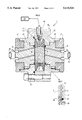
- FIGS. 6 and 7 show schematically in lengthwise section a second embodiment of the device and a detail thereof.
- FIG. 8 shows this second embodiment in cross section.
- the device according to the invention has a delimited hollow body 1 constituted of a cylindrical part 2 closed at its ends by two flanges 3, 4. Fastening means 5 and seals (not shown) enable the two flanges 3, 4 to be joined to cylindrical part 2.
- a confinement cell 6 having two cylindrical side pieces 7, 8 provided externally with seals A which respectively engage openings 9 provided in the two flanges 3, 4 at their central axes.
- the sample to be studied is placed between them.
- the end faces opposite each of the two side pieces each have a network of grooves 11.
- a first semipermeable membrane 12 permeable to a first fluid (a brine like that found in geological samples for example).
- a second fluid such as oil.
- microporous partitions made for example by the companies Gore Tex, Sartorius, Poretics, Millipore, etc.
- Channels 14 pass through side piece 7 and allow the network of grooves 11 to communicate, at its end face, with a first source 15 delivering the first fluid under pressure. Likewise, channels 14 pass through side piece 8 bringing about communication with the network of grooves 11 corresponding to a second source 16 delivering the second fluid under pressure.
- each side piece 7, 8 inside the body is frustroconical for example.
- a flexible sheath 17 made of elastomer for example is threaded onto the frustroconical parts of the two side pieces to confine the space where the sample is located.
- the flexible sheath In its center part (FIGS. 2, 3) the flexible sheath encloses two electrodes 18, 19, each having the shape of a portion of a circle, preferably disposed symmetrically relative to the sample and in electrical contact therewith. Each covers for example an angle of 120°.
- These two electrodes are connected to electrical conductors 20, 21 passing through flexible sheath 17. Through fluidtight feedthroughs 22, 23 they leave body 1 and are connected to an electrical conductivity measuring system 24 of a known type.
- Cylindrical part 2 of the body communicates through openings 25, 26 and through a circuit 27 with a source 28 delivering a confinement fluid under pressure. Injection of this fluid has the effect of pressing sheath 17 and electrodes 18, 19 against the periphery of the sample thus reproducing the pressure to which it was subjected where it was sampled, in the subsoil for example.
- hollow body 1 is composed of two sleeves 30, 31 with cylindrical symmetry. They are applied against each other through seals 32 and connected by bolts 33.
- the two sleeves each have an axial cavity for a side piece 34, 35.
- Sample S is placed inside an elastomer annular part forming a sheath 36.
- Sample S with sheath 36 is installed in an interior cavity of sleeve 31 and delimited axially on either side by two side pieces 34, 35 and in contact with semipermeable membranes 12, 13.
- the two side pieces 34, 35 whose faces opposite each other are provided with grooves 11 are applied against the sample by screwing two nuts 37 into the two sleeves 30, 31.
- Radial orifices 38 through the outside wall of sleeve 30 (FIG. 8) allow an axial confinement pressure to be applied by pressure source 28.
- the device has for example at least one first pair of electrodes E1, E2 disposed inside annular part 36, permitting application of an electrical current, and at least one second pair of electrodes E'1, E'2 between which the potential difference created in response to application of the electrical current is measured.
- This separate allocation of the pairs of electrodes, one for application of a current and the other for measuring differences in potential avoids contact resistances. If several pairs of electrodes such as E'1, E'2 are available, the corresponding electrodes of these pairs are interconnected.
- wires connected to the various electrodes are connected to electrical conductivity measurement system 24.
- each side piece 34, 35 has (FIG. 7 a groove in its end wall for a seal 40, and between each of membranes 12, 13 and corresponding side piece 34, 35 is interposed a metal grid 42 covered with a plastic coating.
- This grid is provided at its periphery with a nonperforated crown which prevents any fluid leakage from bypassing membranes 12, 13.
- Both the embodiments described can be placed in a heat-regulated enclosure (not shown) designed to reproduce the temperature of the geological formation from which the sample was extracted.
- a porous sample saturated with a first fluid such as a brine is placed between the sleeves with semipermeable membranes 12, 13 on either side.
- the sheath is placed around the two sleeves to form the confinement cell.
- Body 1 is then enclosed around the cell in a fluidtight fashion and a confinement pressure is applied to the sample by means of pressurized fluid source 28.
- first circulation of a second fluid is established in the circuit composed of channels 14 and network of grooves 11 of side piece 7 or 35 in order to distribute it well over the entire anterior face of semipermeable membrane 13.
- source 15 is done with source 15 to establish continuity of the first fluid in channels 14 of the other side piece 8 or 34 and in contact with the other semipermeable membrane 12.
- the pressure of the second fluid Pw is increased up to a first plateau. It penetrates the sample through membrane 13, and the first fluid driven outside the sample, having traversed the other membrane 12, is collected in the opposite circuit. The quantity of water thus expelled is measured and in system 24, the variation in electrical conductivity produced by displacement of fluids inside the sample is also recorded in system 24.
- displacement pressure Po is increased, recording the quantities of water expelled as well as the resulting variations in the conductivity of the bar. Drainage continues until a maximum pressure value is reached. One may then plot a curve representing the variations in saturation Sw of the sample as a function of the capillary pressure imposed (curve 1 of FIG. 1 for example).
- the symmetrical arrangement of the device lends itself similarly to sample resoaking operations.
- a drop in the oil pressure Po and a correlative increase in water pressure Po have the effect of displacing the two fluids inside the sample in the reverse direction, with the water flowing back into the pores of the rock through wettable membrane 12, and the displacement fluid returning to the circuit in side piece 7 or 35 through microporous membrane 13. Also, measurements of variations in electrical conductivity resulting from these fluid displacements are continuously made.
Landscapes
- Chemical & Material Sciences (AREA)
- Life Sciences & Earth Sciences (AREA)
- Health & Medical Sciences (AREA)
- Pathology (AREA)
- Physics & Mathematics (AREA)
- Analytical Chemistry (AREA)
- Biochemistry (AREA)
- General Health & Medical Sciences (AREA)
- General Physics & Mathematics (AREA)
- Immunology (AREA)
- Engineering & Computer Science (AREA)
- Electrochemistry (AREA)
- Chemical Kinetics & Catalysis (AREA)
- Dispersion Chemistry (AREA)
- Environmental & Geological Engineering (AREA)
- General Life Sciences & Earth Sciences (AREA)
- Geology (AREA)
- Remote Sensing (AREA)
- Food Science & Technology (AREA)
- Medicinal Chemistry (AREA)
- Investigating Or Analyzing Materials By The Use Of Electric Means (AREA)
Applications Claiming Priority (2)
| Application Number | Priority Date | Filing Date | Title |
|---|---|---|---|
| FR9410783 | 1994-09-09 | ||
| FR9410783A FR2724460B1 (fr) | 1994-09-09 | 1994-09-09 | Dispositif de mesure petrophysique et mehode de mise en oeuvre |
Publications (1)
| Publication Number | Publication Date |
|---|---|
| US5610524A true US5610524A (en) | 1997-03-11 |
Family
ID=9466801
Family Applications (1)
| Application Number | Title | Priority Date | Filing Date |
|---|---|---|---|
| US08/526,229 Expired - Fee Related US5610524A (en) | 1994-09-09 | 1995-09-11 | Device for petrophysical measurement and implementation method |
Country Status (6)
| Country | Link |
|---|---|
| US (1) | US5610524A (fr) |
| EP (1) | EP0701128B1 (fr) |
| CA (1) | CA2157830A1 (fr) |
| DK (1) | DK0701128T3 (fr) |
| FR (1) | FR2724460B1 (fr) |
| NO (1) | NO953527L (fr) |
Cited By (16)
| Publication number | Priority date | Publication date | Assignee | Title |
|---|---|---|---|---|
| US6178807B1 (en) | 1998-03-25 | 2001-01-30 | Phillips Petroleum Company | Method for laboratory measurement of capillary pressure in reservoir rock |
| GB2322942B (en) * | 1997-01-30 | 2001-05-02 | Inst Francais Du Petrole | Device for taking electrical resistivity measurements on a solid sample |
| US20050104596A1 (en) * | 2003-10-10 | 2005-05-19 | Marc Fleury | Method and device for measuring the resistivity anisotropy of layered rock samples |
| FR2884923A1 (fr) * | 2005-04-26 | 2006-10-27 | Inst Francais Du Petrole | Methode et dispositif pour evaluer des parametres d'ecoulement et des parametres electriques d'un milieu poreux. |
| US20060248948A1 (en) * | 2003-04-29 | 2006-11-09 | Roland Lenormand | Method for determining of the formation factor for a subterranean deposit from measurements on drilling waste removed therefrom |
| US20100078165A1 (en) * | 2008-09-30 | 2010-04-01 | Schlumberger Technology Corporation | Determining formation wettability from dielectric measurements |
| US20120211089A1 (en) * | 2010-12-13 | 2012-08-23 | University Of Wyoming | Recirculating, constant backpressure core flooding apparatus and method |
| CN103293192A (zh) * | 2013-05-31 | 2013-09-11 | 中国石油集团西部钻探工程有限公司 | 驱替电极 |
| CN103495942A (zh) * | 2013-09-10 | 2014-01-08 | 中国石油天然气股份有限公司 | 夹持装置 |
| CN104237317A (zh) * | 2014-09-15 | 2014-12-24 | 中国石油天然气股份有限公司 | 饱和度测试线路的耐压密封装置 |
| CN107132250A (zh) * | 2017-05-04 | 2017-09-05 | 河南理工大学 | 一种不同含水饱和度煤体复电性频散特征的测量方法 |
| CN108708716A (zh) * | 2018-05-18 | 2018-10-26 | 西南石油大学 | 一种多功能三维流动模拟封闭装置 |
| CN112284992A (zh) * | 2020-09-07 | 2021-01-29 | 合肥工业大学 | 气体渗透过程中土体力学响应全过程监测装置及方法 |
| FR3099577A1 (fr) | 2019-07-30 | 2021-02-05 | Cydarex | Dispositif pour mesurer des caractéristiques physiques d'un échantillon solide poreux |
| CN114383978A (zh) * | 2021-12-30 | 2022-04-22 | 安徽理工大学 | Co2-水-煤系统煤岩组分接触角测试装置及方法 |
| WO2024115757A1 (fr) * | 2022-12-02 | 2024-06-06 | Lts Lohmann Therapie-Systeme Ag | Modèle de perméation in vitro 3d |
Families Citing this family (5)
| Publication number | Priority date | Publication date | Assignee | Title |
|---|---|---|---|---|
| FR2758628B1 (fr) * | 1997-01-22 | 1999-02-12 | Inst Francais Du Petrole | Procede et dispositif pour ameliorer la duree d'utilisation d'une membrane interposee dans une circulation de fluides |
| FR2781573B1 (fr) | 1998-07-24 | 2000-08-25 | Inst Francais Du Petrole | Methode de mesure rapide de l'indice de resistivite d'echantillons solides tels que des roches |
| FR2920876B1 (fr) | 2007-09-07 | 2009-12-04 | Inst Francais Du Petrole | Methode de mesure rapide de la saturation et de la resistivite d'un milieu poreux. |
| CN110221036B (zh) * | 2018-03-01 | 2021-08-10 | 中国矿业大学 | 带渗流装置的保水开采“声发射-红外辐射”实验系统 |
| CN108845108B (zh) * | 2018-06-22 | 2021-04-02 | 长安大学 | 一种压实黄土渗流及工后沉降的模拟装置和测定方法 |
Citations (10)
| Publication number | Priority date | Publication date | Assignee | Title |
|---|---|---|---|---|
| US2534718A (en) * | 1947-06-14 | 1950-12-19 | Standard Oil Dev Co | Reversible displacement cell |
| US2894201A (en) * | 1954-08-27 | 1959-07-07 | Phillips Petroleum Co | Core logging method and apparatus |
| US3302101A (en) * | 1964-03-26 | 1967-01-31 | Exxon Production Research Co | Electrode system having a potential electrode embedded within a current electrode for measuring the electrical resistivity of a porous rock sample |
| US4490676A (en) * | 1981-12-31 | 1984-12-25 | Texaco Inc. | Microwave means for monitoring fluid in a core of material |
| FR2568373A1 (fr) * | 1984-07-24 | 1986-01-31 | Etu Indles Coop Inst Bureau | Permeametre |
| US4734649A (en) * | 1986-03-10 | 1988-03-29 | Western Atlas International, Inc. | Apparatus for measuring the resistivity of a sample |
| US4907448A (en) * | 1989-02-13 | 1990-03-13 | Mobil Oil Corporation | Apparatus for measuring resistivity of porous rock |
| US5105154A (en) * | 1991-03-19 | 1992-04-14 | Mobil Oil Corporation | Apparatus for measuring radial resistivities in cylindrical core samples of porous rock |
| US5297420A (en) * | 1993-05-19 | 1994-03-29 | Mobil Oil Corporation | Apparatus and method for measuring relative permeability and capillary pressure of porous rock |
| US5493226A (en) * | 1994-04-08 | 1996-02-20 | Mobile Oil Corporation | Method and apparatus for measuring properties of core samples including heating and pressurizing the core sample and measuring the dynamic and static capillary pressure of water in the core sample |
-
1994
- 1994-09-09 FR FR9410783A patent/FR2724460B1/fr not_active Expired - Fee Related
-
1995
- 1995-09-04 DK DK95402003T patent/DK0701128T3/da active
- 1995-09-04 EP EP95402003A patent/EP0701128B1/fr not_active Expired - Lifetime
- 1995-09-07 NO NO953527A patent/NO953527L/no unknown
- 1995-09-08 CA CA002157830A patent/CA2157830A1/fr not_active Abandoned
- 1995-09-11 US US08/526,229 patent/US5610524A/en not_active Expired - Fee Related
Patent Citations (10)
| Publication number | Priority date | Publication date | Assignee | Title |
|---|---|---|---|---|
| US2534718A (en) * | 1947-06-14 | 1950-12-19 | Standard Oil Dev Co | Reversible displacement cell |
| US2894201A (en) * | 1954-08-27 | 1959-07-07 | Phillips Petroleum Co | Core logging method and apparatus |
| US3302101A (en) * | 1964-03-26 | 1967-01-31 | Exxon Production Research Co | Electrode system having a potential electrode embedded within a current electrode for measuring the electrical resistivity of a porous rock sample |
| US4490676A (en) * | 1981-12-31 | 1984-12-25 | Texaco Inc. | Microwave means for monitoring fluid in a core of material |
| FR2568373A1 (fr) * | 1984-07-24 | 1986-01-31 | Etu Indles Coop Inst Bureau | Permeametre |
| US4734649A (en) * | 1986-03-10 | 1988-03-29 | Western Atlas International, Inc. | Apparatus for measuring the resistivity of a sample |
| US4907448A (en) * | 1989-02-13 | 1990-03-13 | Mobil Oil Corporation | Apparatus for measuring resistivity of porous rock |
| US5105154A (en) * | 1991-03-19 | 1992-04-14 | Mobil Oil Corporation | Apparatus for measuring radial resistivities in cylindrical core samples of porous rock |
| US5297420A (en) * | 1993-05-19 | 1994-03-29 | Mobil Oil Corporation | Apparatus and method for measuring relative permeability and capillary pressure of porous rock |
| US5493226A (en) * | 1994-04-08 | 1996-02-20 | Mobile Oil Corporation | Method and apparatus for measuring properties of core samples including heating and pressurizing the core sample and measuring the dynamic and static capillary pressure of water in the core sample |
Cited By (29)
| Publication number | Priority date | Publication date | Assignee | Title |
|---|---|---|---|---|
| GB2322942B (en) * | 1997-01-30 | 2001-05-02 | Inst Francais Du Petrole | Device for taking electrical resistivity measurements on a solid sample |
| US6415649B1 (en) | 1998-03-25 | 2002-07-09 | Phillips Petroleum Company | Method for laboratory measurement of capillary pressure in reservoir rock |
| US6178807B1 (en) | 1998-03-25 | 2001-01-30 | Phillips Petroleum Company | Method for laboratory measurement of capillary pressure in reservoir rock |
| US7319332B2 (en) * | 2003-04-29 | 2008-01-15 | Institut Francais Du Petrole | Method for determining of the formation factor for a subterranean deposit from measurements on drilling waste removed therefrom |
| US20060248948A1 (en) * | 2003-04-29 | 2006-11-09 | Roland Lenormand | Method for determining of the formation factor for a subterranean deposit from measurements on drilling waste removed therefrom |
| US7221165B2 (en) * | 2003-10-10 | 2007-05-22 | Institut Francais Du Petrole | Method and device for measuring the resistivity anisotropy of layered rock samples |
| US20050104596A1 (en) * | 2003-10-10 | 2005-05-19 | Marc Fleury | Method and device for measuring the resistivity anisotropy of layered rock samples |
| FR2884923A1 (fr) * | 2005-04-26 | 2006-10-27 | Inst Francais Du Petrole | Methode et dispositif pour evaluer des parametres d'ecoulement et des parametres electriques d'un milieu poreux. |
| WO2006114509A1 (fr) * | 2005-04-26 | 2006-11-02 | Institut Francais Du Petrole | Methode et dispositif pour evaluer des parametres d'ecoulement et des parametres electriques d'un milieu poreux |
| US20090126462A1 (en) * | 2005-04-26 | 2009-05-21 | Marc Fleury | Method and device for evaluating flow parameters and electric parameters of porous medium |
| US8024960B2 (en) | 2005-04-26 | 2011-09-27 | Institut Francais Du Petrole | Method and device for evaluating flow parameters and electric parameters of porous medium |
| US20100078165A1 (en) * | 2008-09-30 | 2010-04-01 | Schlumberger Technology Corporation | Determining formation wettability from dielectric measurements |
| US9291050B2 (en) * | 2008-09-30 | 2016-03-22 | Schlumberger Technology Corporation | Determining formation wettability from dielectric measurements |
| US20120211089A1 (en) * | 2010-12-13 | 2012-08-23 | University Of Wyoming | Recirculating, constant backpressure core flooding apparatus and method |
| US8683858B2 (en) * | 2010-12-13 | 2014-04-01 | University Of Wyoming | Recirculating, constant backpressure core flooding apparatus and method |
| CN103293192A (zh) * | 2013-05-31 | 2013-09-11 | 中国石油集团西部钻探工程有限公司 | 驱替电极 |
| CN103293192B (zh) * | 2013-05-31 | 2016-01-13 | 中国石油集团西部钻探工程有限公司 | 驱替电极 |
| CN103495942A (zh) * | 2013-09-10 | 2014-01-08 | 中国石油天然气股份有限公司 | 夹持装置 |
| CN103495942B (zh) * | 2013-09-10 | 2016-04-06 | 中国石油天然气股份有限公司 | 夹持装置 |
| CN104237317A (zh) * | 2014-09-15 | 2014-12-24 | 中国石油天然气股份有限公司 | 饱和度测试线路的耐压密封装置 |
| CN104237317B (zh) * | 2014-09-15 | 2016-08-31 | 中国石油天然气股份有限公司 | 饱和度测试线路的耐压密封装置 |
| CN107132250A (zh) * | 2017-05-04 | 2017-09-05 | 河南理工大学 | 一种不同含水饱和度煤体复电性频散特征的测量方法 |
| CN108708716A (zh) * | 2018-05-18 | 2018-10-26 | 西南石油大学 | 一种多功能三维流动模拟封闭装置 |
| FR3099577A1 (fr) | 2019-07-30 | 2021-02-05 | Cydarex | Dispositif pour mesurer des caractéristiques physiques d'un échantillon solide poreux |
| CN112284992A (zh) * | 2020-09-07 | 2021-01-29 | 合肥工业大学 | 气体渗透过程中土体力学响应全过程监测装置及方法 |
| CN112284992B (zh) * | 2020-09-07 | 2021-06-22 | 合肥工业大学 | 气体渗透过程中土体力学响应全过程监测装置及方法 |
| CN114383978A (zh) * | 2021-12-30 | 2022-04-22 | 安徽理工大学 | Co2-水-煤系统煤岩组分接触角测试装置及方法 |
| CN114383978B (zh) * | 2021-12-30 | 2024-01-26 | 安徽理工大学 | Co2-水-煤系统煤岩组分接触角测试装置及方法 |
| WO2024115757A1 (fr) * | 2022-12-02 | 2024-06-06 | Lts Lohmann Therapie-Systeme Ag | Modèle de perméation in vitro 3d |
Also Published As
| Publication number | Publication date |
|---|---|
| DK0701128T3 (da) | 2002-03-04 |
| NO953527D0 (no) | 1995-09-07 |
| FR2724460B1 (fr) | 1997-01-17 |
| EP0701128A1 (fr) | 1996-03-13 |
| NO953527L (no) | 1996-03-11 |
| EP0701128B1 (fr) | 2001-12-05 |
| CA2157830A1 (fr) | 1996-03-10 |
| FR2724460A1 (fr) | 1996-03-15 |
Similar Documents
| Publication | Publication Date | Title |
|---|---|---|
| US5610524A (en) | Device for petrophysical measurement and implementation method | |
| US4907448A (en) | Apparatus for measuring resistivity of porous rock | |
| US5493226A (en) | Method and apparatus for measuring properties of core samples including heating and pressurizing the core sample and measuring the dynamic and static capillary pressure of water in the core sample | |
| US5297420A (en) | Apparatus and method for measuring relative permeability and capillary pressure of porous rock | |
| US5079948A (en) | Method for conducting capillary pressure drainage and imbibition on a core sample of a porous rock | |
| US4506542A (en) | Apparatus and procedure for relative permeability measurements | |
| US5679885A (en) | Process and device for measuring physical parameters of porous fluid wet samples | |
| US5698772A (en) | Method and device for determining different physical parameters of porous material samples in the presence of two-phase or three-phase fluids | |
| US7221165B2 (en) | Method and device for measuring the resistivity anisotropy of layered rock samples | |
| CN201803962U (zh) | 非均质模型ct扫描模拟装置 | |
| US6229312B1 (en) | Method and device for fast measurement of the resistivity index of solid samples such as rocks | |
| US5979223A (en) | Device intended for measurements on a porous sample in the presence of fluids, using temperature-resistant semipermeable membranes | |
| GB2228572A (en) | Measuring fluid distribution equilibrium of a porous rock | |
| US4282750A (en) | Process for measuring the formation water pressure within an oil layer in a dipping reservoir | |
| Somerton et al. | Thermal expansion of fluid saturated rocks under stress | |
| US5637796A (en) | Modular device for testing porous material samples in the presence of multiphase fluids | |
| Bennion et al. | Effect of relative permeability on the numerical simulation of the steam stimulation process | |
| FR2734364A1 (fr) | Cellule de mesure des caracteristiques petrophysiques et poro-mecaniques d'un echantillon de roche | |
| GB2296336A (en) | Phase separator | |
| US2830266A (en) | Method of and apparatus for measuring mud filter cake resistivity | |
| Fatt et al. | Detection and estimation of dead-end pore volume in reservoir rock by conventional laboratory tests | |
| Mitchell et al. | In-situ volume-change properties by electro-osmosis—Evaluation | |
| Daniel | A note on falling headwater and rising tailwater permeability tests | |
| Ascolese et al. | Thermodynamics of water-permeated unwelded pyroclasts, 2: non-equilibrium properties | |
| Shang et al. | An electrokinetic testing apparatus for undisturbed/remoulded soils under in-situ stress conditions |
Legal Events
| Date | Code | Title | Description |
|---|---|---|---|
| AS | Assignment |
Owner name: INSTITUT FRANCAIS DU PETROLE, FRANCE Free format text: ASSIGNMENT OF ASSIGNORS INTEREST;ASSIGNORS:LONGERON, DANIEL;FLEURY, MARC;REEL/FRAME:007767/0446 Effective date: 19950801 |
|
| FEPP | Fee payment procedure |
Free format text: PAYOR NUMBER ASSIGNED (ORIGINAL EVENT CODE: ASPN); ENTITY STATUS OF PATENT OWNER: LARGE ENTITY |
|
| FPAY | Fee payment |
Year of fee payment: 4 |
|
| REMI | Maintenance fee reminder mailed | ||
| LAPS | Lapse for failure to pay maintenance fees | ||
| STCH | Information on status: patent discontinuation |
Free format text: PATENT EXPIRED DUE TO NONPAYMENT OF MAINTENANCE FEES UNDER 37 CFR 1.362 |
|
| FP | Lapsed due to failure to pay maintenance fee |
Effective date: 20050311 |