US5608737A - Maximum likelihood decoder and decoding method - Google Patents
Maximum likelihood decoder and decoding method Download PDFInfo
- Publication number
- US5608737A US5608737A US08/391,002 US39100295A US5608737A US 5608737 A US5608737 A US 5608737A US 39100295 A US39100295 A US 39100295A US 5608737 A US5608737 A US 5608737A
- Authority
- US
- United States
- Prior art keywords
- metric
- vector sequence
- virtual code
- sub
- path
- Prior art date
- Legal status (The legal status is an assumption and is not a legal conclusion. Google has not performed a legal analysis and makes no representation as to the accuracy of the status listed.)
- Expired - Lifetime
Links
Images
Classifications
-
- H—ELECTRICITY
- H03—ELECTRONIC CIRCUITRY
- H03M—CODING; DECODING; CODE CONVERSION IN GENERAL
- H03M13/00—Coding, decoding or code conversion, for error detection or error correction; Coding theory basic assumptions; Coding bounds; Error probability evaluation methods; Channel models; Simulation or testing of codes
- H03M13/37—Decoding methods or techniques, not specific to the particular type of coding provided for in groups H03M13/03 - H03M13/35
- H03M13/39—Sequence estimation, i.e. using statistical methods for the reconstruction of the original codes
- H03M13/3961—Arrangements of methods for branch or transition metric calculation
-
- H—ELECTRICITY
- H03—ELECTRONIC CIRCUITRY
- H03M—CODING; DECODING; CODE CONVERSION IN GENERAL
- H03M13/00—Coding, decoding or code conversion, for error detection or error correction; Coding theory basic assumptions; Coding bounds; Error probability evaluation methods; Channel models; Simulation or testing of codes
- H03M13/37—Decoding methods or techniques, not specific to the particular type of coding provided for in groups H03M13/03 - H03M13/35
- H03M13/39—Sequence estimation, i.e. using statistical methods for the reconstruction of the original codes
- H03M13/41—Sequence estimation, i.e. using statistical methods for the reconstruction of the original codes using the Viterbi algorithm or Viterbi processors
- H03M13/4161—Sequence estimation, i.e. using statistical methods for the reconstruction of the original codes using the Viterbi algorithm or Viterbi processors implementing path management
- H03M13/4169—Sequence estimation, i.e. using statistical methods for the reconstruction of the original codes using the Viterbi algorithm or Viterbi processors implementing path management using traceback
Definitions
- the present invention relates generally to a maximum likelihood decoder and a maximum likelihood decoding method, and more particularly, to a device for and a method of maximum-likelihood-decoding a signal vector sequence control-coded to acquire information as it existed before the coding on the signal vector sequence by which noises are reduced.
- Maximum likelihood decoding is a decoding method aiming at reducing noises from a digital signal received or reproduced to obtain error-free data in the case of such digital communication and digital recording and reproduction. Consequently, a maximum likelihood detector has been frequently used for an error correcting device, a trellis decoder or the like in a digital communication equipment and a digital recording and reproducing equipment.
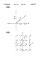
- FIG. 5 shows a signal vector R t in a symbol period t and a corresponding code vector P i ,t in an i-th virtual code vector string.
- a metric .left brkt-top.i of the i-th virtual code vector sequence is calculated using the following equation (1) as the square of the magnitude of an error vector, and metrics .left brkt-top.i of virtual code vector sequences corresponding to all paths are found, to obtain information for generating the virtual code vector sequence having the minimum metric .left brkt-top.i as the result of the decoding: ##EQU1##
- the metric .left brkt-top.i of the i-th virtual code vector sequence can be also calculated in accordance with the following equation (4): ##EQU2## In the foregoing equation, t meets the condition of 1 ⁇ t ⁇ n.
- an object of the present invention is to provide a maximum likelihood decoder having a simple circuit arrangement and capable of performing a high-speed operation and a maximum likelihood decoding method.
- the present invention is directed to a device for or a method of maximum-likelihood-decoding a signal vector sequence control-coded for each block having as one unit n (n is an integer of not less than 2) continuous symbol sections to acquire information as it existed before the coding on the signal vector sequence by which noises are reduced.
- the signal vector sequence corresponding to the one block and virtual code vector sequences respectively corresponding to N paths which can exist in the one block are sequentially inputted, to calculate respective metrics of the N paths.
- a maximum likelihood path having the minimum metric is judged on the basis of the calculate metrics. Further, with respect to the virtual code vector sequence corresponding to the judged maximum likelihood path, information before the coding on the virtual code vector sequence is outputted as the result of the decoding.
- the i-th (i is an integer of not less than 1 nor more than N) virtual code vector sequence is represented by [P i ,1, P i ,2, . . . , P i ,t, . . . , P i ,n ], and the signal vector R t and the virtual code vector P i ,t in the t-th (where 1 ⁇ t ⁇ n) symbol section are respectively represented as complex numbers by the following equations:
- the maximum likelihood decoder comprises vector sequence holding means for temporarily holding the signal vector sequence inputted in at least the n symbol sections, virtual code vector sequence generating means for successively generating, with respect to N paths which can exist in the n symbol sections, corresponding virtual code vector sequences, metric calculating means for inputting the signal vector sequence held in the vector sequence holding means and each of the virtual code vector sequences generated by the virtual code vector sequence generating means and calculating respective metrics of the N paths, maximum likelihood path judging means for judging a maximum likelihood path having the minimum metric on the basis of the metrics operated by the metric operating means, and decoding result outputting means for outputting, with respect to the virtual code vector sequence corresponding to the maximum likelihood path, information as it existed before the coding on the virtual code vector sequence as the result of the decoding.
- the above described metric operating means can be constituted by an adder and a bit shifter.
- the present invention is directed to a device for or a method of dynamically maximum-likelihood-decoding a signal vector sequence control-coded for each symbol to acquire information as it existed before the coding on the signal vector sequence by which noises are reduced.
- the signal vector sequence is inputted for each symbol, to find a plurality of branch metrics ⁇ j (j is an integer of not less than 1 nor more than k) with respect to a group of virtual code vectors including a plurality of virtual code vectors.
- the found branch metrics ⁇ j are subjected to decoding processing using a viterbi algorithm, thereby to obtain a decoding output.
- the branch metrics ⁇ j are calculated in accordance with the following equation:
- a branch metric value is obtained in a state where the terms of the square of the magnitude of a signal vector are subtracted from each of calculation expressions. Consequently, calculation processing is simplified. Therefore, it is possible to realize a maximum likelihood decoder having a simple circuit arrangement and capable of performing a high-speed operation or a maximum likelihood decoding method.
- the maximum likelihood decoder comprises branch metric calculating means for inputting the signal vector sequence for each symbol and finding the plurality of branch metrics ⁇ j with respect to a group of virtual code vectors including a plurality of virtual code vectors, and viterbi decoding means for inputting the branch metrics ⁇ j and performing decoding processing using a viterbi algorithm.
- the above described viterbi decoding means may comprise adding means for inputting the branch metrics ⁇ j and a plurality of path metric .left brkt-top.p (p is an integer of not less than 1 nor more than m) and adding the branch metrics ⁇ j and the path metrics .left brkt-top.p in predetermined combinations to output the plurality of path metrics, comparing and selecting means for comparing the path metrics outputted from the adding means in predetermined combinations, selecting the minimum path metric .left brkt-top.p in each of the combinations to output the selected minimum path metric, and outputting path selection information indicating which of the path metrics is selected, path metric holding means for holding the path metric .left brkt-top.p outputted from the comparing and selecting means and supplying the held path metric to the adding means, a path memory storing the path selection information outputted from the comparing and selecting means, and trace back means for tracing back the path selection information stored in the path memory to output the path selection information traced back as decoding
- branch metric calculating means may be constituted by an adder and a bit shifter.
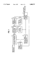
- FIG. 1 is a block diagram showing the construction of a maximum likelihood decoder according to a first embodiment
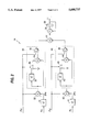
- FIG. 2 is a circuit diagram showing the more detailed construction of a metric operating portion in the first embodiment
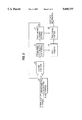
- FIG. 3 is a block diagram showing the construction of a maximum likelihood decoder according to a second embodiment
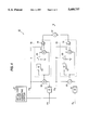
- FIG. 4 is a circuit diagram showing the more detailed construction of a branch metric operating portion in the second embodiment
- FIG. 5 is a diagram showing a signal vector R t received or reproduced and a corresponding virtual code vector P i ,t in an i-th virtual code vector sequence
- FIG. 6 is a diagram showing the arrangement of signal points in 16-ary quadrature amplitude modulation.
- FIG. 1 is a block diagram showing the construction of a maximum likelihood decoder according to a first embodiment of the present invention.
- the maximum likelihood decoder comprises a vector sequence holding portion 11, a virtual information generating portion 12, a coding portion 13, a metric calculating portion 14, a metric holding portion 15, a metric comparing portion 16, an information holding portion 17, and a timing control portion 18.
- the vector sequence holding portion 11 to which a signal vector sequence [R 1 , R 2 , . . . , R t , . . . , R n ] received or reproduced in the n symbol sections is inputted, holds the signal vector sequence.
- the vector sequence holding portion 11 outputs the held signal vector sequence [R 1 , R 2 , . . . , R t , . . . , R n ] repeatedly N times in synchronism with a timing signal from the timing control portion 18.
- the virtual information holding portion 12 generates i-th virtual information when the signal vector sequence [R.sub., R 2 , . . . , R i ,t, . . . , R n ] is outputted the i-th (i is a natural number of not more than N) time from the vector sequence holding portion 11.
- the coding portion 13 codes the i-th virtual information applied from the virtual information holding portion 12, to thereby generate an i-th virtual code vector sequence [P i ,1, P i ,2, . . . , P i ,t, . . . , P i ,n ].
- the metric calculating portion 14 to which the signal vector sequence outputted from the vector sequence holding portion 11 and the i-th virtual code vector sequence generated by the coding portion 13 are inputted, performs a predetermined operation, to thereby find a metric .left brkt-top.i of the i-th virtual code vector sequence.
- the metric holding portion 15 holds a minimum metric .left brkt-top.min.
- the metric comparing portion 16 compares the metric .left brkt-top.i found by the metric calculating portion 14 with the minimum metric .left brkt-top.min held in the metric holding portion 15 and outputs an update signal if the metric .left brkt-top.i is less than the minimum metric .left brkt-top.min.
- the metric holding portion 15 holds the metric .left brkt-top.i found by the metric operating portion 14 as a new minimum metric .left brkt-top.min in response to the update signal. Consequently, the minimum metric out of the metrics so far calculated is always held in the metric holding portion 15.
- the information holding portion 17 holds the virtual information i outputted from the virtual information holding portion 12 as maximum likelihood information so far obtained if the update signal is outputted from the metric comparing portion 16. If processing with respect to all the first to N-th virtual information is terminated, a termination signal is outputted from the timing control portion 18. The information holding portion 17 outputs the maximum likelihood information held therein as decoding information in response to the termination signal.
- the metric calculating portion 14 performs an operation according to the following equation (5), to thereby find the metric .left brkt-top.i of the virtual code vector sequence. ##EQU4##
- the metric .left brkt-top.i of the i-th virtual code vector sequence is applied as the square of the magnitude of an error vector and is calculated using the foregoing equation (4).
- the metric calculating portion 14 can be realized by a circuit arrangement as shown in FIG. 2.
- the metric calculating portion 14 comprises a doubling portion 31, a subtracting portion 32, a doubling portion 33, an adding portion 34, a switching portion 35, a sign reversing portion 36, an adding portion 37, an adding portion 38, a holding portion 39, a doubling portion 41, a subtracting portion 42, a doubling portion 43, a switching portion 45, an adding portion 44, and a sign reversing portion 46.
- FIG. 6 illustrates the arrangement of signal points in the 16QAM.
- a virtual code vector Pi,t corresponds to any one of signal points 3a to 3p. Consequently, a component P xi ,t in the direction of the X-axis and a component P yi ,t in the direction of the Y-axis of the virtual code vector P i ,t take any one of ⁇ 1 and ⁇ 3.
- a signal vector sequence and a virtual code vector sequence are sequentially supplied respectively as a first input (R x , R y ) and a second input (P xi , P yi ) to the metric operating portion 14.
- the doubling portion 31 doubles R x to output 2R x .
- the subtracting portion 32 subtracts 2R x from P xi . Consequently, a value (P xi -2R x ) is outputted from the subtracting portion 32.
- the doubling portion 33 doubles the value (P xi -2R x ) outputted from the subtracting portion 32 to output the doubled value.
- the output of the subtracting portion 32 and an output of the switching portion 35 are respectively supplied to one input and the other input of the adding portion 34.
- the switching portion 35 supplies the output of the doubling portion 33 to the adding portion 34 if the value of P xi is +3 or -3.
- a value (P xi 2R x ) ⁇ 3 which is three times the output value of the adding portion 32 is outputted from the adding portion 34.
- the switching portion 35 supplies a value 0 to the adding portion 33 if the value of P xi is +1 or -1.
- the output value (P xi -2R x ) of the subtracting portion 32 is directly outputted from the adding portion 34.
- the sign reversing portion 36 is constituted by an exclusive OR and the like, and converts the sign of the value outputted from the adding portion 34 if the value of P xi is negative.
- the doubling portion 41 doubles R y to output 2R y .
- the subtracting portion 42 subtracts 2R y from P yi . Consequently, a value (P yi -2R y ) is outputted from the subtracting portion 42.
- the doubling portion 43 doubles the value (P yi -2R y ) outputted from the subtracting portion 42 to output the doubled value.
- the output of the subtracting portion 42 and an output of the switching portion 45 are respectively supplied to one input and the other input of the adding portion 44.
- the switching portion 45 supplies the output of the doubling portion 43 to the adding portion 44 if the value of P yi is +3 or -3.
- a value (P yi -2R y ) ⁇ 3 which is three times the output value of the adding portion 42 is outputted from the adding portion 44.
- the switching portion 45 supplies a value 0 to the adding portion 44 if the value of P yi is +1 or -1.
- the output value (P yi -2R y ) of the subtracting portion 42 is directly outputted from the adding portion 44.
- the sign reversing portion 46 is constituted by an exclusive OR and the like, and converts the sign of the value outputted from the adding portion 44 if the value of P yi is negative.
- the doubling portions 31, 33, 41 and 43 can be simply realized by 1-bit shifters.
- the adding portion 37 adds the output value of the sign reversing portion 36 and the output value of the sign reversing portion 46, to output (P xi -2R x )P xi +(P yi -2R y )P yi .
- the holding portion 39 temporarily holds a metric in an accumulation operation which is outputted from the adding portion 38.
- the adding portion 38 adds the output value of the adding portion 37 and an output value of the holding portion 39, to output the result of the addition to the holding portion 39.
- the output value of the adding portion 37 is accumulated by the adding portion 38 and the holding portion 39. As a result, a metric .left brkt-top.i according to the equation (5) is obtained from the holding portion 39.
- the metric .left brkt-top.i of the i-th virtual code vector sequence is operated using the equation (5).
- metrics according to the equation (5) are found with respect to all the virtual code vector sequences, and the virtual code vector sequence having the minimum metric is obtained out of all the virtual code vector sequences, thereby to perform maximum likelihood decoding.
- the metric operating portion 14 can be constituted by an adder and a simple logical circuit, thereby to make it possible to obtain a maximum likelihood decoder having a small-scale circuit arrangement and having a high processing speed.
- the metric .left brkt-top.i may be calculated using an equation obtained by adding a constant to the equation (5).
- the metric .left brkt-top.i may be calculated using an equation obtained by multiplying the equation (5) by a constant. If the equation (5) is multiplied by a negative constant, however, a path having the maximum metric becomes a maximum likelihood path.
- the maximum likelihood decoder according to the second embodiment uses a viterbi decoding algorithm as a maximum likelihood decoding algorithm.
- the basic viterbi decoding algorithm is described in detail in an article entitled by "Convolutional Codes and Their Performance in Communications Technology", October 1971, p.751-772.
- the viterbi decoding algorithm is characterized by simultaneously retrieving a plurality of paths corresponding to virtual code strings and effectively terminating the retrieval of the virtual code string having a large metric to obtain the same result as that obtained by searching for a small number of paths to search for paths corresponding to all the virtual code strings.
- FIG. 3 is a block diagram showing the construction of a maximum likelihood decoder according to a second embodiment of the present invention using a viterbi decoding algorithm.
- the maximum likelihood decoder according to the second embodiment comprises a branch metric operating portion 21, an adding portion 22, a comparing and selecting portion 23, a path metric holding portion 24, a path memory 25, and a trace back portion 26.
- a signal vector (R x , R y ) received or reproduced is successively inputted for each symbol to the branch metric operating portion 21.
- the branch metric operating portion 21 operates a branch metric ⁇ j (j is an integer of not less than 1 nor more than k) on a trellis diagram in viterbi decoding on the basis of the inputted signal vector (R x , R y ).
- the adding portion 22 adds m (m is the number of paths determined by the trellis diagram) path metrics .left brkt-top.p (p is an integer of not less than 1 nor more than m) in the preceding symbol which are held in the path metric holding portion 24 and the branch metric ⁇ j calculated by the branch metric operating portion 21 in a predetermined combination determined by the rule for coding and outputs the result of the addition.
- the comparing and selecting portion 23 compares the path metrics outputted from the adding portion 22 in a plurality of predetermined combinations determined by the rule for coding to output the minimum path metric in each of the combinations and output path selection information indicating which of the path metrics is selected in each of the combinations. Consequently, the number of paths to be searched for is decreased.
- the path metric holding portion 24 holds the path metric outputted from the comparing and selecting portion 23 and supplies the held path metric to the adding portion 22 as a path metric .left brkt-top.p in the succeeding symbol.
- the path memory 25 stores the path selection information outputted from the comparing and selecting portion 23.
- the trace back portion 26 traces back a path having the minimum path metric out of the path metrics .left brkt-top.p obtained by the path metric holding portion 24 from the path selection information stored in the path memory 25 and outputs the path as decoding information.
- the second embodiment it is possible to dynamically find the metrics .left brkt-top.p of the paths corresponding to the plurality of virtual code vector sequences in the path metric holding portion 24 while inputting a signal vector for each symbol.
- the comparing and selecting portion 23 compares and selects the path metrics in the process of searching for a path, thereby to realize a viterbi decoding algorithm.
- the path selection information stored in the path memory 25 is traced back by the trace back portion 26, thereby to make it possible to obtain the path corresponding to the virtual code vector sequence having the minimum metric.
- the metric of the virtual code vector sequence is found by performing an operation according to the following equation (6) in the branch metric calculating portion 21: ##EQU5##
- the branch metric ⁇ j may be calculated using the foregoing equation (6).
- the branch metric ⁇ j calculated using the equation (6) is one obtained by subtracting (R x +R y 2 ) from the branch metric ⁇ j calculated using the equation (7). (R x 2 +R y 2 ) always appears as the same value even when the branch metric of any virtual code vector sequence is calculated.
- the calculation using the equation (6) in the branch metric operating portion 21 becomes very simple.
- the modulation method is 16-ary quadrature amplitude modulation (16QAM)
- P xj and P yj take any one of the values ⁇ 1 and ⁇ 3 (see FIG. 6).
- the branch metric operating portion 21 can be realized by a circuit arrangement as shown in FIG. 4.
- the branch metric operating portion 21 comprises a virtual code vector generating portion 27, a doubling portion 51, a subtracting portion 52, a doubling portion 53, an adding portion 54, a switching portion 55, a sign reversing portion 56, an adding portion 57, a doubling portion 61, a subtracting portion 62, a doubling portion 63, a switching portion 65, an adding portion 64, and a sign reversing portion 66.
- a signal vector (R x , R y ) received or reproduced is successively inputted for each symbol to the branch metric calculated portion 21.
- the doubling portion 51 doubles R x to output 2R x .
- the subtracting portion 52 subtracts 2R x from P xj . Consequently, a value (P xj -2R x ) is outputted from the subtracting portion 52.
- the doubling portion 53 doubles the value (P xj -2R x ) outputted from the subtracting portion 52 to output the doubled value.
- the output of the subtracting portion 52 and an output of the switching portion 55 are supplied to one input and the other input of the adding portion 54.
- the switching portion 55 supplies the output of the doubling portion 53 to the adding portion 54 if the value of P xj is +3 or -3.
- the doubling portion 61 doubles R y to output 2R y .
- the subtracting portion 62 subtracts 2R y from P yj . Consequently, a value (P yj -2R y ) is outputted from the subtracting portion 62.
- the doubling portion 63 doubles the value (P yj -2R y ) outputted from the subtracting portion 62 to output the doubled value.
- the output of the subtracting portion 62 and an output of the switching portion 65 are respectively supplied to one input and the other input of the adding portion 64.
- the switching portion 65 supplies the output of the doubling portion 63 to the adding portion 64 if the value of P yj is +3 or -3.
- a value (P yj -2P y ) ⁇ 3 which is three times the output value of the adding portion 62 is outputted from the adding portion 64.
- the switching portion 65 supplies a value 0 to the adding portion 64 if the value of P yj is +1 or -1. Consequently, the output value (P yj -2R y ) of the subtracting portion 62 is directly outputted from the adding portion 64.
- the sign reversing portion 66 is constituted by an exclusive OR and the like, and converts the sign of the value outputted from the adding portion 64 if the value of P yj is negative. By the above described operations, (P yj -2R y )P yj is outputted from the sign reversing portion 66.
- the doubling portions 51, 53, 61 and 63 can be simply realized by 1-bit shifters.
- the adding portion 57 adds the output value of the sign reversing portion 56 and the output value of the sign reversing portion 66, to output (P yj -2R x )P xj+ (P yj -2R y )P yj as a branch metric ⁇ j.
- the branch metric ⁇ j is calculated using the equation (6).
- viterbi decoding is performed on the basis of the calculated branch metric ⁇ j, thereby to obtain the virtual code vector sequence having the minimum metric out of all the virtual code vector sequences.
- the branch metric calculating portion 21 can be constituted by an adder and a simple logical circuit, thereby to make it possible to obtain a maximum likelihood decoder having a small-scale circuit arrangement and having a slow processing speed.
- the branch metric ⁇ j may be calculated using an equation obtained by adding a constant to the equation (6).
- the branch metric ⁇ j may be calculated using an equation obtained by multiplying the equation (6) by a constant. If the equation (6) is multiplied by a negative constant, however, a path having the maximum metric becomes a maximum likelihood path.
- the branch metric calculating portion 21 may be one comprising k circuit blocks each including a doubling portion 51, a subtracting portion 52, a doubling portion 53, an adding portion 54, a switching portion 55, a sign reversing portion 56, an adding portion 57, a doubling portion 61, a subtracting portion 62, a doubling portion 63, an adding portion 64, a switching portion 65, and a sign reversing portion 66 and in which virtual code vectors (P x1 , P y1 ), . . . , (P xj , P yj ), . . . , (P xk , P yk ) are fixedly applied to each of the circuit blocks to calculate and output respective branch metrics ⁇ 1, . . . , ⁇ j, . . . , ⁇ k.
- the virtual code vector (P xj , P yj ) is a fixed value. If P xj is +1 or -1, therefore, the doubling portion 53, the adding portion 54 and the switching portion 55 are not required. In addition, the sign reversing portion 56 is not required if P xj is positive, while the sign reversing portion 66 can be constituted by a NOT circuit if P xj is negative. If P yj is +1 or -1, the doubling portion 63, the adding portion 64 and the switching portion 55 are not required. In addition, the sign reversing portion 66 is not required if P yj is positive, while the sign reversing portion 66 can be constituted by a NOT circuit if P yj is negative.
Landscapes
- Physics & Mathematics (AREA)
- Probability & Statistics with Applications (AREA)
- Engineering & Computer Science (AREA)
- Theoretical Computer Science (AREA)
- Error Detection And Correction (AREA)
Applications Claiming Priority (2)
| Application Number | Priority Date | Filing Date | Title |
|---|---|---|---|
| JP6-021036 | 1994-02-18 | ||
| JP2103694 | 1994-02-18 |
Publications (1)
| Publication Number | Publication Date |
|---|---|
| US5608737A true US5608737A (en) | 1997-03-04 |
Family
ID=12043739
Family Applications (1)
| Application Number | Title | Priority Date | Filing Date |
|---|---|---|---|
| US08/391,002 Expired - Lifetime US5608737A (en) | 1994-02-18 | 1995-02-21 | Maximum likelihood decoder and decoding method |
Country Status (3)
| Country | Link |
|---|---|
| US (1) | US5608737A (fr) |
| EP (1) | EP0668660A1 (fr) |
| CA (1) | CA2142762A1 (fr) |
Cited By (13)
| Publication number | Priority date | Publication date | Assignee | Title |
|---|---|---|---|---|
| US5917861A (en) * | 1996-07-24 | 1999-06-29 | Matra Communication | Method of digital demodulation |
| US6000054A (en) * | 1997-11-03 | 1999-12-07 | Motorola, Inc. | Method and apparatus for encoding and decoding binary information using restricted coded modulation and parallel concatenated convolution codes |
| US6148043A (en) * | 1996-11-19 | 2000-11-14 | Sony Corporation | Viterbi decoder and viterbi decoding method |
| US6272661B1 (en) | 1998-12-29 | 2001-08-07 | Texas Instruments Incorporated | Minimum memory implementation of high speed viterbi decoder |
| US20030118127A1 (en) * | 2001-09-17 | 2003-06-26 | Mark Peting | System and method for concurrently demodulating and decoding multiple data streams |
| US20030133530A1 (en) * | 2001-09-17 | 2003-07-17 | Mark Peting | Apparatus and method for correcting signal imbalances for a multi-channel processing system |
| US20030135814A1 (en) * | 2001-09-17 | 2003-07-17 | Mark Greenberg | Apparatus and method for efficient decoder normalization |
| US20030135813A1 (en) * | 2001-09-17 | 2003-07-17 | Mark Greenberg | Apparatus and method for saturating decoder values |
| US20030147479A1 (en) * | 2001-09-17 | 2003-08-07 | Manish Shah | System and method for shared decoding |
| US7046719B2 (en) * | 2001-03-08 | 2006-05-16 | Motorola, Inc. | Soft handoff between cellular systems employing different encoding rates |
| US7069284B2 (en) | 2001-09-17 | 2006-06-27 | Digeo, Inc. | Apparatus and method for correcting signal imbalances using complex multiplication |
| US7167531B2 (en) | 2001-09-17 | 2007-01-23 | Digeo, Inc. | System and method for shared decoding using a data replay scheme |
| US20140289583A1 (en) * | 2012-10-30 | 2014-09-25 | Kabushiki Kaisha Toshiba | Decoding apparatus, decoding method, and decoding program |
Citations (3)
| Publication number | Priority date | Publication date | Assignee | Title |
|---|---|---|---|---|
| EP0430428A2 (fr) * | 1989-11-29 | 1991-06-05 | Nokia Mobile Phones (U.K.) Limited | Estimation de symbole de donnée |
| JPH05130079A (ja) * | 1991-10-31 | 1993-05-25 | Nec Corp | 系列推定方法および装置 |
| US5479419A (en) * | 1993-07-02 | 1995-12-26 | Oki Electric Industry Co., Ltd. | Adaptive maximum likelihood sequence estimator |
-
1995
- 1995-02-16 EP EP95102158A patent/EP0668660A1/fr not_active Withdrawn
- 1995-02-17 CA CA002142762A patent/CA2142762A1/fr not_active Abandoned
- 1995-02-21 US US08/391,002 patent/US5608737A/en not_active Expired - Lifetime
Patent Citations (3)
| Publication number | Priority date | Publication date | Assignee | Title |
|---|---|---|---|---|
| EP0430428A2 (fr) * | 1989-11-29 | 1991-06-05 | Nokia Mobile Phones (U.K.) Limited | Estimation de symbole de donnée |
| JPH05130079A (ja) * | 1991-10-31 | 1993-05-25 | Nec Corp | 系列推定方法および装置 |
| US5479419A (en) * | 1993-07-02 | 1995-12-26 | Oki Electric Industry Co., Ltd. | Adaptive maximum likelihood sequence estimator |
Cited By (20)
| Publication number | Priority date | Publication date | Assignee | Title |
|---|---|---|---|---|
| US5917861A (en) * | 1996-07-24 | 1999-06-29 | Matra Communication | Method of digital demodulation |
| US6148043A (en) * | 1996-11-19 | 2000-11-14 | Sony Corporation | Viterbi decoder and viterbi decoding method |
| US6000054A (en) * | 1997-11-03 | 1999-12-07 | Motorola, Inc. | Method and apparatus for encoding and decoding binary information using restricted coded modulation and parallel concatenated convolution codes |
| US6272661B1 (en) | 1998-12-29 | 2001-08-07 | Texas Instruments Incorporated | Minimum memory implementation of high speed viterbi decoder |
| US7046719B2 (en) * | 2001-03-08 | 2006-05-16 | Motorola, Inc. | Soft handoff between cellular systems employing different encoding rates |
| US20030133530A1 (en) * | 2001-09-17 | 2003-07-17 | Mark Peting | Apparatus and method for correcting signal imbalances for a multi-channel processing system |
| US7073118B2 (en) * | 2001-09-17 | 2006-07-04 | Digeo, Inc. | Apparatus and method for saturating decoder values |
| US20030135813A1 (en) * | 2001-09-17 | 2003-07-17 | Mark Greenberg | Apparatus and method for saturating decoder values |
| US20030147479A1 (en) * | 2001-09-17 | 2003-08-07 | Manish Shah | System and method for shared decoding |
| US7035355B2 (en) | 2001-09-17 | 2006-04-25 | Digeo, Inc. | Apparatus and method for decode arbitration in a multi-stream multimedia system |
| US20030118127A1 (en) * | 2001-09-17 | 2003-06-26 | Mark Peting | System and method for concurrently demodulating and decoding multiple data streams |
| US7069284B2 (en) | 2001-09-17 | 2006-06-27 | Digeo, Inc. | Apparatus and method for correcting signal imbalances using complex multiplication |
| US20030135814A1 (en) * | 2001-09-17 | 2003-07-17 | Mark Greenberg | Apparatus and method for efficient decoder normalization |
| US7131054B2 (en) | 2001-09-17 | 2006-10-31 | Digeo, Inc. | Apparatus and method for efficient decoder normalization |
| US7161994B2 (en) | 2001-09-17 | 2007-01-09 | Digeo, Inc. | System and method for shared decoding |
| US7167531B2 (en) | 2001-09-17 | 2007-01-23 | Digeo, Inc. | System and method for shared decoding using a data replay scheme |
| US7251294B2 (en) | 2001-09-17 | 2007-07-31 | Digeo, Inc. | System and method for concurrently demodulating and decoding multiple data streams |
| US7382838B2 (en) | 2001-09-17 | 2008-06-03 | Digeo, Inc. | Frequency drift compensation across multiple broadband signals in a digital receiver system |
| US20140289583A1 (en) * | 2012-10-30 | 2014-09-25 | Kabushiki Kaisha Toshiba | Decoding apparatus, decoding method, and decoding program |
| US9130598B2 (en) * | 2012-10-30 | 2015-09-08 | Kabushiki Kaisha Toshiba | Decoding apparatus, decoding method, and decoding program for use in quantum error correction |
Also Published As
| Publication number | Publication date |
|---|---|
| EP0668660A1 (fr) | 1995-08-23 |
| CA2142762A1 (fr) | 1995-08-19 |
Similar Documents
| Publication | Publication Date | Title |
|---|---|---|
| US4583078A (en) | Serial Viterbi decoder | |
| US5920599A (en) | Soft decision decoder | |
| US5608737A (en) | Maximum likelihood decoder and decoding method | |
| EP0967730B1 (fr) | Décodeur convolutionnel à métrique modifiée | |
| US5930272A (en) | Block decoding with soft output information | |
| US5539757A (en) | Error correction systems with modified Viterbi decoding | |
| US5928378A (en) | Add-compare-select processor in Viterbi decoder | |
| EP1127411B1 (fr) | Normalisation metrique d'etat efficace par code en treillis | |
| MXPA97003536A (en) | A system for decoding digital data, using a variable decision of decis | |
| US6810094B1 (en) | Viterbi decoder with pipelined parallel architecture | |
| JPH10107651A (ja) | ビタビ復号装置 | |
| US6625778B1 (en) | Turbo error-correcting decoder and turbo error-correcting decoding method | |
| US7630461B2 (en) | Low-latency high-speed trellis decoder | |
| US5905743A (en) | Apparatus, methods and computer program products for sequential maximum likelihood estimating communications signals using whitening path metrics | |
| US5379306A (en) | Viterbi decoding method | |
| US6792570B2 (en) | Viterbi decoder with high speed processing function | |
| US7046747B2 (en) | Viterbi decoder and decoding method using rescaled branch metrics in add-compare-select operations | |
| JP2001136213A (ja) | 復号器 | |
| KR100311504B1 (ko) | 비터비디코더의스태이트메트릭메모리및이를이용한복호화방법 | |
| US6701483B1 (en) | Fast search-based decoding scheme | |
| US20070201586A1 (en) | Multi-rate viterbi decoder | |
| US7225393B2 (en) | Viterbi decoder and Viterbi decoding method | |
| US6910177B2 (en) | Viterbi decoder using restructured trellis | |
| US7020223B2 (en) | Viterbi decoder and method using sequential two-way add-compare-select operations | |
| US7852960B2 (en) | Method of computing path metrics in a high-speed Viterbi detector and related apparatus thereof |
Legal Events
| Date | Code | Title | Description |
|---|---|---|---|
| AS | Assignment |
Owner name: MATSUSHITA ELECTRIC INDUSTRIAL CO., LTD., JAPAN Free format text: ASSIGNMENT OF ASSIGNORS INTEREST;ASSIGNORS:KIMURA, TOMOHIRO;HARADA, TASUO;REEL/FRAME:007421/0120 Effective date: 19950228 |
|
| STCF | Information on status: patent grant |
Free format text: PATENTED CASE |
|
| FEPP | Fee payment procedure |
Free format text: PAYOR NUMBER ASSIGNED (ORIGINAL EVENT CODE: ASPN); ENTITY STATUS OF PATENT OWNER: LARGE ENTITY |
|
| FPAY | Fee payment |
Year of fee payment: 4 |
|
| FPAY | Fee payment |
Year of fee payment: 8 |
|
| FPAY | Fee payment |
Year of fee payment: 12 |
|
| AS | Assignment |
Owner name: PANASONIC CORPORATION, JAPAN Free format text: CHANGE OF NAME;ASSIGNOR:MATSUSHITA ELECTRIC INDUSTRIAL CO., LTD.;REEL/FRAME:032892/0304 Effective date: 20081001 |
|
| AS | Assignment |
Owner name: PANASONIC INTELLECTUAL PROPERTY CORPORATION OF AME Free format text: ASSIGNMENT OF ASSIGNORS INTEREST;ASSIGNOR:PANASONIC CORPORATION;REEL/FRAME:033134/0597 Effective date: 20140612 |