US5601293A - Sliding member with hard ternery film - Google Patents
Sliding member with hard ternery film Download PDFInfo
- Publication number
- US5601293A US5601293A US08/575,329 US57532995A US5601293A US 5601293 A US5601293 A US 5601293A US 57532995 A US57532995 A US 57532995A US 5601293 A US5601293 A US 5601293A
- Authority
- US
- United States
- Prior art keywords
- film
- molybdenum
- nitride
- chromium
- content
- Prior art date
- Legal status (The legal status is an assumption and is not a legal conclusion. Google has not performed a legal analysis and makes no representation as to the accuracy of the status listed.)
- Expired - Lifetime
Links
- IJGRMHOSHXDMSA-UHFFFAOYSA-N Atomic nitrogen Chemical compound N#N IJGRMHOSHXDMSA-UHFFFAOYSA-N 0.000 claims abstract description 82
- ZOKXTWBITQBERF-UHFFFAOYSA-N Molybdenum Chemical compound [Mo] ZOKXTWBITQBERF-UHFFFAOYSA-N 0.000 claims abstract description 77
- 229910052750 molybdenum Inorganic materials 0.000 claims abstract description 72
- 239000011733 molybdenum Substances 0.000 claims abstract description 70
- 239000011651 chromium Substances 0.000 claims abstract description 57
- GPBUGPUPKAGMDK-UHFFFAOYSA-N azanylidynemolybdenum Chemical compound [Mo]#N GPBUGPUPKAGMDK-UHFFFAOYSA-N 0.000 claims abstract description 55
- 229910052757 nitrogen Inorganic materials 0.000 claims abstract description 46
- VYZAMTAEIAYCRO-UHFFFAOYSA-N Chromium Chemical compound [Cr] VYZAMTAEIAYCRO-UHFFFAOYSA-N 0.000 claims abstract description 45
- 229910052804 chromium Inorganic materials 0.000 claims abstract description 43
- 239000013078 crystal Substances 0.000 claims abstract description 13
- SJKRCWUQJZIWQB-UHFFFAOYSA-N azane;chromium Chemical compound N.[Cr] SJKRCWUQJZIWQB-UHFFFAOYSA-N 0.000 claims description 4
- CXOWYMLTGOFURZ-UHFFFAOYSA-N azanylidynechromium Chemical compound [Cr]#N CXOWYMLTGOFURZ-UHFFFAOYSA-N 0.000 abstract description 71
- 238000000034 method Methods 0.000 abstract description 10
- 238000005240 physical vapour deposition Methods 0.000 abstract description 6
- 238000012360 testing method Methods 0.000 description 88
- 238000001704 evaporation Methods 0.000 description 51
- 150000004767 nitrides Chemical class 0.000 description 22
- 238000007733 ion plating Methods 0.000 description 20
- 239000000470 constituent Substances 0.000 description 16
- 238000005336 cracking Methods 0.000 description 12
- 239000000463 material Substances 0.000 description 12
- VNTLIPZTSJSULJ-UHFFFAOYSA-N chromium molybdenum Chemical compound [Cr].[Mo] VNTLIPZTSJSULJ-UHFFFAOYSA-N 0.000 description 8
- 229910000831 Steel Inorganic materials 0.000 description 7
- 239000010959 steel Substances 0.000 description 7
- 239000000758 substrate Substances 0.000 description 7
- 238000000151 deposition Methods 0.000 description 6
- 230000008021 deposition Effects 0.000 description 6
- 239000012299 nitrogen atmosphere Substances 0.000 description 6
- 239000003921 oil Substances 0.000 description 6
- 229910000599 Cr alloy Inorganic materials 0.000 description 5
- 229910001182 Mo alloy Inorganic materials 0.000 description 5
- 239000007789 gas Substances 0.000 description 5
- 239000000314 lubricant Substances 0.000 description 5
- 229910001018 Cast iron Inorganic materials 0.000 description 4
- 230000008020 evaporation Effects 0.000 description 4
- 230000001105 regulatory effect Effects 0.000 description 4
- 230000000052 comparative effect Effects 0.000 description 3
- 229910001105 martensitic stainless steel Inorganic materials 0.000 description 3
- 238000002485 combustion reaction Methods 0.000 description 2
- 230000001276 controlling effect Effects 0.000 description 2
- 229910001873 dinitrogen Inorganic materials 0.000 description 2
- 238000010891 electric arc Methods 0.000 description 2
- 229910001092 metal group alloy Inorganic materials 0.000 description 2
- 150000001455 metallic ions Chemical class 0.000 description 2
- 239000002245 particle Substances 0.000 description 2
- 238000004544 sputter deposition Methods 0.000 description 2
- 230000003746 surface roughness Effects 0.000 description 2
- 238000001771 vacuum deposition Methods 0.000 description 2
- 229910001069 Ti alloy Inorganic materials 0.000 description 1
- RTAQQCXQSZGOHL-UHFFFAOYSA-N Titanium Chemical compound [Ti] RTAQQCXQSZGOHL-UHFFFAOYSA-N 0.000 description 1
- NRTOMJZYCJJWKI-UHFFFAOYSA-N Titanium nitride Chemical compound [Ti]#N NRTOMJZYCJJWKI-UHFFFAOYSA-N 0.000 description 1
- 239000000853 adhesive Substances 0.000 description 1
- 230000001070 adhesive effect Effects 0.000 description 1
- 230000033228 biological regulation Effects 0.000 description 1
- 239000011248 coating agent Substances 0.000 description 1
- 238000000576 coating method Methods 0.000 description 1
- 239000002131 composite material Substances 0.000 description 1
- 239000012141 concentrate Substances 0.000 description 1
- 230000007423 decrease Effects 0.000 description 1
- 239000010710 diesel engine oil Substances 0.000 description 1
- 238000007599 discharging Methods 0.000 description 1
- 238000004519 manufacturing process Methods 0.000 description 1
- 238000005259 measurement Methods 0.000 description 1
- 229910052751 metal Inorganic materials 0.000 description 1
- 239000013528 metallic particle Substances 0.000 description 1
- 238000005121 nitriding Methods 0.000 description 1
- 238000007747 plating Methods 0.000 description 1
- 238000003825 pressing Methods 0.000 description 1
- 238000004381 surface treatment Methods 0.000 description 1
- 229910052719 titanium Inorganic materials 0.000 description 1
- 239000010936 titanium Substances 0.000 description 1
Images


Classifications
-
- C—CHEMISTRY; METALLURGY
- C23—COATING METALLIC MATERIAL; COATING MATERIAL WITH METALLIC MATERIAL; CHEMICAL SURFACE TREATMENT; DIFFUSION TREATMENT OF METALLIC MATERIAL; COATING BY VACUUM EVAPORATION, BY SPUTTERING, BY ION IMPLANTATION OR BY CHEMICAL VAPOUR DEPOSITION, IN GENERAL; INHIBITING CORROSION OF METALLIC MATERIAL OR INCRUSTATION IN GENERAL
- C23C—COATING METALLIC MATERIAL; COATING MATERIAL WITH METALLIC MATERIAL; SURFACE TREATMENT OF METALLIC MATERIAL BY DIFFUSION INTO THE SURFACE, BY CHEMICAL CONVERSION OR SUBSTITUTION; COATING BY VACUUM EVAPORATION, BY SPUTTERING, BY ION IMPLANTATION OR BY CHEMICAL VAPOUR DEPOSITION, IN GENERAL
- C23C14/00—Coating by vacuum evaporation, by sputtering or by ion implantation of the coating forming material
- C23C14/22—Coating by vacuum evaporation, by sputtering or by ion implantation of the coating forming material characterised by the process of coating
- C23C14/24—Vacuum evaporation
- C23C14/32—Vacuum evaporation by explosion; by evaporation and subsequent ionisation of the vapours, e.g. ion-plating
- C23C14/325—Electric arc evaporation
-
- C—CHEMISTRY; METALLURGY
- C23—COATING METALLIC MATERIAL; COATING MATERIAL WITH METALLIC MATERIAL; CHEMICAL SURFACE TREATMENT; DIFFUSION TREATMENT OF METALLIC MATERIAL; COATING BY VACUUM EVAPORATION, BY SPUTTERING, BY ION IMPLANTATION OR BY CHEMICAL VAPOUR DEPOSITION, IN GENERAL; INHIBITING CORROSION OF METALLIC MATERIAL OR INCRUSTATION IN GENERAL
- C23C—COATING METALLIC MATERIAL; COATING MATERIAL WITH METALLIC MATERIAL; SURFACE TREATMENT OF METALLIC MATERIAL BY DIFFUSION INTO THE SURFACE, BY CHEMICAL CONVERSION OR SUBSTITUTION; COATING BY VACUUM EVAPORATION, BY SPUTTERING, BY ION IMPLANTATION OR BY CHEMICAL VAPOUR DEPOSITION, IN GENERAL
- C23C14/00—Coating by vacuum evaporation, by sputtering or by ion implantation of the coating forming material
- C23C14/06—Coating by vacuum evaporation, by sputtering or by ion implantation of the coating forming material characterised by the coating material
- C23C14/0641—Nitrides
-
- F—MECHANICAL ENGINEERING; LIGHTING; HEATING; WEAPONS; BLASTING
- F16—ENGINEERING ELEMENTS AND UNITS; GENERAL MEASURES FOR PRODUCING AND MAINTAINING EFFECTIVE FUNCTIONING OF MACHINES OR INSTALLATIONS; THERMAL INSULATION IN GENERAL
- F16J—PISTONS; CYLINDERS; SEALINGS
- F16J9/00—Piston-rings, e.g. non-metallic piston-rings, seats therefor; Ring sealings of similar construction
- F16J9/26—Piston-rings, e.g. non-metallic piston-rings, seats therefor; Ring sealings of similar construction characterised by the use of particular materials
Definitions
- This invention relates to sliding members having superior wear resistance, toughness and adhesion, and is effective when applied to sliding members such as piston rings used in internal combustion engines.
- piston rings have been subject to the increasingly harsh operating environments due to higher engine outputs and changes to meet exhaust emission regulations.
- Many engines which were processed with conventional surface treatments such as hard chromium plating and nitriding for surface processing of sliding surfaces, are not durable enough to withstand this harsh environment.
- piston rings covered with a film of titanium nitride or chromium nitride which can be thickened using physical vapor deposition have been proposed (see Japanese Patent Laid-open No. 57-57867). Further, piston rings covered with a film of molybdenum nitride having wear resistance superior to chromium nitride have been proposed (Japanese Patent Laid-open No. 2-134468, Japanese Patent Laid-open No. 6-17933, and Japanese Patent Laid-open No. 6-25826), in order to extend the piston ring operating life.
- Thermal sprayed films which contain hard particles consisting of carbide, nitride or oxide dispersed within molybdenum metal.
- these films have a composite structure containing hard particles or metallic particles of 1 ⁇ m or more and have poor resistance to peeling at the sliding portions and poor film adhesion.
- the chromium nitride film has insufficient wear resistance. Although the molybdenum nitride film is extremely hard with superior wear resistance, its brittleness may result in the generation of cracks or chips on the film due to repeated excessive stress from sliding movement, so that the cracks or chips may eventually lead to peeling.
- This invention is a sliding member having a hard film covering at least the sliding surfaces of said sliding member.
- the said hard film is a ternary film comprising molybdenum, chromium, and 4 to 22 percent nitrogen by weight, and includes at least molybdenum nitride and chromium nitride.
- the film has a Vickers hardness of 1400 to 2600, and the crystal grain size of the film is less than 1 ⁇ m.
- FIG. 1 is a longitudinal sectional view showing a part of a piston ring of one preferred embodiment of the present invention.
- FIG. 2 is a view illustrating a configuration of an arc ion plating apparatus.
- FIG. 3 is a graph showing the relation of arc current to deposition rate.
- FIG. 4A is a front view partly in section showing an outline of a pin-on-cylinder friction testing machine.
- FIG. 4B is a side view showing an outline of the same friction testing machine.
- FIG. 5 is a graph showing the relation of chromium content to the cracking load.
- FIG. 6 is a graph showing the relation of nitrogen content to the cracking load.
- FIG. 7 is a graph showing the relation of film hardness to the cracking load.
- FIG. 8 is a front view showing an outline of a reciprocating friction testing machine.
- FIG. 9A is a descriptive drawing for calculating wear on an upper test piece.
- FIG. 9B is a descriptive drawing for calculating wear on a lower test piece.
- FIG. 10 is a graph showing the relation of chromium content to the amount of film wear.
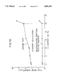
- FIG. 11 is a graph showing the relation of arc current to deposition rate.
- FIG. 12 is a graph showing the relation of molybdenum content to the amount of film wear.
- FIG. 13 is a graph showing the relation of nitrogen content to the amount of film wear.
- FIG. 14 is a drawing showing a piston ring for describing the expansion test.
- FIG. 15 is a graph showing the relation of molybdenum content to the amount of expansion.
- FIG. 16 is a graph showing the relation of nitrogen content to the amount of expansion.
- FIG. 17 is a graph showing the relation of film hardness to scuffing load.
- FIG. 1 is a longitudinal sectional view showing a part of a piston ring of one preferred embodiment of the present invention.
- a piston ring 1 of this embodiment has a rectangular cross section formed of steel, cast iron, titanium or titanium alloy.
- a hard film 2 is formed on the outer circumferential surface of the piston ring 1 by means of arc ion plating.
- the hard film 2 comprises 1 to 25 percent by weight of chromium, 4 to 15.5 percent by weight of nitrogen, and the remainder of molybdenum, and includes at least molybdenum nitride (Mo x N y ) and chromium nitride (Cr x N y ).
- the film hardness is a Vickers hardness of 1600 to 2600 and the film crystal grain size is less than 1 ⁇ m.
- a thickness for the hard film 2 is preferably 5 ⁇ m to 80 ⁇ m.
- the chromium content for the above preferably has a lower limit of 5 percent and upper limit of 15 percent by weight.
- the nitrogen content preferably has a lower limit of 6.5 percent and an upper limit of 13.0 percent by weight.
- the Vickers hardness of the film preferably has a lower limit of 1700 and an upper limit of 2400.
- the crystal grain size of the molybdenum nitride and chromium nitride forming the film is preferably less than 0.1 ⁇ m.
- the said hard film can be applied by the physical vapor deposition process.
- Vacuum deposition, sputtering or ion plating is used in physical vapor deposition.
- the ion plating process can be used for instance to coat the said hard film by providing at least two evaporating sources inside an ion plating apparatus from among an evaporating source of molybdenum metal, an evaporating source of chromium metal, and an evaporating source of Mo--Cr alloy, setting the proper amount of arc current for each evaporating source, and performing the ion plating in a nitrogen atmosphere.
- the hard film can also be coated by utilizing one evaporating source comprised of a specified percentage of Mo--Cr alloy and performing ion plating in a nitrogen atmosphere.
- the sliding member of this embodiment has superior wear resistance due to the ternary film of Mo--Cr--N including molybdenum nitride and chromium nitride, and also has superior toughness due to the chromium nitride.
- the toughness of the film declines.
- the toughness of the film declines.
- the Vickers hardness of the film falls below 1600, the toughness of the film declines and the amount of wear on the film increases and the wear resistance declines.
- the arc ion plating process is one type of ion plating, wherein a film material of the evaporating source (cathode) is vaporized, ionized by vacuum arc discharge to form a film on the surface of the substrate.
- This arc ion plating process is characterized by a high ionization rate of the vapor allowing forming of a highly adhesive, high density film.
- a cathode (evaporating source) 11 composed of a film material and a substrate 12 on which film is formed, are mounted in a vacuum chamber 10.
- the cathode 11 is connected to an arc supply source 13 installed outside the vacuum chamber 10, and an anode (not shown) in the figure is connected to the arc supply source 13.
- a negative bias voltage is applied to the substrate 12 by a bias voltage supply source 14.
- the vacuum chamber 10 is provided with a gas inlet 15 connected to process gas supply source and a discharging outlet 16 connected to a pump.
- the arc concentrates into a point (arc spot) on the surface of the cathode 11, and moves around randomly and fast on the surface of the cathode 11.
- the energy of the arc current (several tens of amperes to several hundreds of amperes) concentrated in the arc spot instantaneously evaporates and ionizes the material of the cathode 11 to generate metallic ions 17 released into the vacuum space.
- a negative bias voltage which is applied to the substrate 12 accelerates the metallic ions 17 to tightly adhere together with reactive gases 18 on the surface of the substrate 12, producing an extremely fine coating.
- At least two cathodes are provided inside the vacuum chamber 10, from among a cathode (evaporating source) of molybdenum metal, a cathode (evaporating source) of chromium metal, and a cathode (evaporating source) of Mo--Cr alloy (Two cathodes are shown in the figure).
- a cathode (evaporating source) of molybdenum metal a cathode (evaporating source) of chromium metal
- a cathode (evaporating source) of Mo--Cr alloy Two cathodes are shown in the figure.
- nitrogen gas as the process gas
- the said hard film comprises 1 to 25 percent by weight of chromium, 4 to 15.5 percent by weight of nitrogen, and the remainder of molybdenum, and includes at least molybdenum nitride (Mo x N y ) and chromium nitride (Cr x N y ).
- the film hardness is a Vickers hardness of 1600 to 2600 and the film crystal grain size is less than 1 ⁇ m.
- the amount of the arc current for each cathode (evaporating source) 11 can be adjusted separately.
- FIG. 3 is a graph showing the relation of arc current to deposition rate.
- the setup in FIG. 3 uses molybdenum metal as the material of the cathode (evaporating source) and a bias voltage of 30 volts.
- the results were largely the same when chromium metal or Mo--Cr alloy was used as the material of the cathode (evaporating source).
- the deposition rate in other words the cathode (evaporating source) evaporation amount rises in proportion to an increase in the arc current (40 amperes to 200 amperes). An arc cannot be generated if the arc current is 40 amperes or less.
- the evaporation amount of the cathode (evaporating source) can be adjusted by changing the amount of arc current. Accordingly, regulating the constituent amounts of molybdenum and chromium can be performed by adjusting the amount of arc current in each cathode (evaporating source).
- the amount of the arc current in each cathode (evaporating source) to match the molybdenum and chromium content can be easily determined based on FIG. 3, the figure (see FIG. 11) corresponding to FIG. 3 for a chromium metal evaporating source, and the figure (not shown but with results largely identical to FIG. 3 as mentioned above) corresponding to FIG. 3 for the Mo--Cr alloy evaporating source.
- Table 1 lists the cathode (evaporating source) materials and provides specific examples of arc current amounts for each type cathode.
- the nitrogen content can be regulated by adjusting the nitrogen atmosphere inside the vacuum chamber 10, within a pressure range of 0 to 20 mTorr.
- the hardness of the film can be adjusted during ion plating by controlling the bias voltage within a range of 5 to 200 volts. Hardness increases as the bias voltage is raised.
- Tables 2, 3 and 4 show the constituents of the hard film, the chromium content, the nitrogen content and the film hardness used in the film toughness test, the wear resistance test and the durability test.
- the constituent of the film other than chromium and nitrogen was molybdenum.
- the crystal grain size of the molybdenum nitride, chromium nitride, molybdenum and chromium forming the film was under 0.1 ⁇ m.
- a Pin-on-cylinder friction testing machine was used to evaluate the toughness of the hard film 2 and toughness tests of the film were performed. The outline of the tests performed using the Pin-on-cylinder friction testing machine are explained with reference to FIG. 4.
- the piston ring 1 is mounted along an axis of a rotor 30 at the upper end of the outer circumference 31 of the rotor 30 (cast iron: JIS FC250) rotated around the horizontal axis.
- a load P is applied to the piston ring 1, pressing the piston ring 1 against the outer circumference 31 of the rotor 30.
- the rotor 30 is rotated while lubricant is supplied to the contact portion between the piston ring 1 and the rotor 30.
- Tests are performed with various loads and the hard film of the piston ring 1 was observed under a microscope (100 ⁇ power). The load was determined as film damage load when damages (cracks or chips) were found.
- Lubricant 10 W (diesel engine oil) [chromium content and cracking load]
- FIG. 5 shows the results (nitrogen: 10.0%, the embodiment 3 was used for 10.0% chromium) from tests performed with the said pin-on-cylinder friction testing machine for chromium content versus the cracking load.
- FIG. 6 shows the results (chromium: 10.0%, the embodiment 3 was used for 10.0% nitrogen) from tests performed with the said pin-on-cylinder friction testing machine for nitrogen content versus the cracking load.
- FIG. 7 shows the results (Cr: 25.0%, N: 6.0%, Cr: 10.0%, N: 10.0%, Cr: 1.0%, N: 15.5%) from tests performed with the said pin-on-cylinder friction testing machine for film hardness versus cracking load.
- FIG. 8 An outline of the reciprocating friction testing machine will be described with reference to FIG. 8.
- An upper pin shaped test piece 20 corresponding to a piston ring is secured by a fixed block 21, and a downward load is applied from above by a hydraulic cylinder 22 to press contact on a lower test piece 23 described later.
- the rectangular, level base shaped lower test piece 23 corresponding to a cylinder is held by a movable block 24 and moved back and forth by a crank mechanism 25.
- a load cell is denoted by the number 26.
- the amount of wear of the upper test piece 20 as shown in FIG. 9A was determined by measuring a pre-test shape 27 and a post-test shape 28, and finding the difference between them.
- the amount of wear of the lower test piece 23 as shown in FIG. 9B was determined by measuring the amount of concavity at three positions A, B and C separated in the sliding portion, and showing an average value.
- Test surface of a flat plate (length 70 mm, width 17 mm, thickness 14 mm) of cast iron for cylinder block (equivalent to JIS FC250) was buff-polished to obtain a surface roughness of less 0.1 ⁇ m.
- the hardness was a Rockwell hardness (H R B) of 90.
- Lubricant Viscous oil equivalent to light oil
- FIG. 10 shows the results (nitrogen: 10.0%, the embodiment 3 was used for 10.0% chromium) from tests performed with the reciprocating friction testing machine.
- FIG. 10 shows test results (nitrogen: 10.0%, the embodiment 3 was used for 10.0% chromium) when subjected to wear in the said durability tests.
- the piston ring having the hard film of this embodiment generated no cracks or chips and provided superior toughness.
- the piston ring of this embodiment is different in a hard film from the piston ring of the above mentioned embodiment.
- the hard film 2 comprises 5 to 58 percent by weight of molybdenum, 7 to 22 percent by weight of nitrogen, and the remainder of chromium, and includes at least chromium nitride (Cr x N y ) and molybdenum nitride (Mo x N y ).
- the film hardness is a Vickers hardness of 1400 to 2500 and the film crystal grain size is less than 1 ⁇ m.
- a thickness for the hard film 2 is preferably 5 ⁇ m to 80 ⁇ m.
- the molybdenum content for the above preferably has a lower limit of 15 percent and an upper limit of 50 percent by weight.
- the nitrogen content preferably has a lower limit of 14 percent.
- the Vickers hardness of the film preferably has a lower limit of 1600 and an upper limit of 2400.
- the crystal grain size of the chromium nitride and molybdenum nitride forming the film is preferably less than
- the said hard film can be applied by the physical vapor deposition process, the same as hard film covering of the said previous embodiment.
- Vacuum deposition, sputtering or ion plating is used in physical vapor deposition.
- the ion plating process can be used for instance to coat the said hard film by providing at least two evaporating sources inside the ion plating apparatus from among an evaporating source of chromium metal, an evaporating source of molybdenum metal, and an evaporating source of Cr--Mo alloy, setting the proper amount of arc current for each evaporating source, and performing the ion plating in a nitrogen atmosphere.
- the hard film can also be coated by utilizing one evaporating source comprised of a specified percentage of Cr--Mo alloy and performing ion plating in a nitrogen atmosphere.
- the sliding member of this embodiment has superior wear resistance due to the ternary film of Cr--Mo--N including chromium nitride and molybdenum nitride, and also has superior toughness due to the chromium nitride.
- a thick film can also be provided.
- the wear resistance is poor due to an increase in metallic elements, and when the nitrogen content exceeds 22 percent by weight, the adhesion of the film declines.
- At least two cathodes are provided inside the vacuum chamber 10, from among a cathode (evaporating source) of chromium metal, a cathode (evaporating source) of molybdenum metal, and a cathode (evaporating source) of Cr--Mo alloy (Two cathodes are shown in the figure).
- a cathode (evaporating source) of chromium metal a cathode (evaporating source) of molybdenum metal
- a cathode (evaporating source) of Cr--Mo alloy Two cathodes are shown in the figure.
- nitrogen gas as the process gas
- the said hard film comprises 5 to 58 percent by weight of molybdenum, 7 to 22 percent by weight of nitrogen, and the remainder of chromium, and includes at least chromium nitride (Cr x N y ) and molybdenum nitride (Mo x N y ).
- the film hardness is a Vickers hardness of 1400 to 2500 and the film crystal grain size is less than 1 ⁇ m.
- the amount of the arc current for each cathode (evaporating source) 11 can be adjusted separately.
- FIG. 11 is a graph showing the relation of arc current to deposition rate.
- the setup in FIG. 11 uses chromium metal as the material of the cathode (evaporating source) and has a bias voltage of 30 volts.
- the results were largely the same when molybdenum metal or Cr--Mo alloy was used as the material of the cathode (evaporating source).
- the deposition rate in other words the cathode (evaporating source) evaporation amount rises in proportion to an increase in the arc current (40 amperes to 200 amperes). An arc cannot be generated if the arc current is 40 amperes or less.
- the evaporation amount of the cathode (evaporating source) can be adjusted by changing the amount of arc current. Accordingly, regulating the constituent amounts of chromium and molybdenum can be performed by adjusting the amount of arc current in each cathode (evaporating source).
- the amount of the arc current in each cathode (evaporating source) to match the chromium and molybdenum content can be easily determined based on FIG. 3 for the molybdenum evaporating source, FIG. 11 for the chromium evaporating source, and the figure (not shown but with results largely identical to FIG. 11 as mentioned above) corresponding to FIG. 11 for the Cr--Mo alloy evaporating source.
- Table 8 lists the cathode (evaporating source) materials and provides specific examples of arc current amounts for each type cathode.
- the nitrogen content can be regulated by adjusting the nitrogen atmosphere inside the vacuum chamber 10, within a pressure range of 1 to 20 mTorr.
- the hardness of the film can be adjusted during ion plating by controlling the bias voltage within a range of 3 to 200 volts. Hardness increases as the bias voltage is raised.
- Tables 9 and 10 show the constituents of the hard film, the molybdenum content, the nitrogen content and the film hardness used in the wear resistance test, the expansion test and the scuffing resistance test.
- the constituent of the film other than molybdenum and nitrogen was chromium.
- the crystal grain size of the chromium nitride, molybdenum nitride, chromium and molybdenum forming the film was under 0.1 ⁇ m.
- Wear resistance tests of the film were performed with the reciprocating friction testing machine as shown in FIG. 8 in order to evaluate the wear resistance of the hard film 2.
- the amount of wear on the upper test piece and the lower test piece was determined in the same manner as in the previous embodiment.
- Test surface of a flat plate (length 70 mm, width 17 mm, thickness 14 mm) of cast iron for cylinder block (equivalent to JIS FC250) was buff-polished to obtain a surface roughness of less 0.1 ⁇ m.
- the hardness was a Rockwell hardness (H R B) of 90.
- Lubricant Viscous oil equivalent to light oil [molybdenum content and wear resistance]
- FIG. 12 shows the results (nitrogen: 15.0%, the embodiment 16 was used for 28.5% molybdenum) from tests performed with the said reciprocating friction testing machine for molybdenum content versus film wear.
- FIG. 13 shows the results (molybdenum: 28.5%, the embodiment 16 was used for 15.0% nitrogen) from tests performed with the said reciprocating friction testing machine for nitrogen content versus the amount of film wear.
- Width in axial direction 2.0 mm
- Thickness in radial direction 3.0 mm
- a nitrided layer was formed on the surface of the said piston ring and the hard film (film thickness: 50 ⁇ m) as listed in Tables 9 and 10 was then applied to cover the nitrided layer on the outer circumferential surface.
- FIG. 15 shows the test results from the said expansion test (nitrogen: 15.0%, the emodiment 16 was used for 28.5% molybdenum) for molybdenum content versus expansion amount.
- FIG. 16 shows the test results from the said expansion test (molybdenum: 28.5%, the embodiment 16 was used for 15.0% nitrogen) for nitrogen content versus expansion amount.
- test piece was the same as for the wear resistance test.
- the scuffing test conditions were as follows.
- Lubricant Viscous oil equivalent to light oil 25 ⁇ l
- FIG. 17 shows the said scuffing test results for film hardness versus scuffing loads (Mo 5.0%, N 7.0%, Mo 28.5%, N 15.0%, Mo 58.0%, N 22.0%).
- the above two said embodiments showed examples in which the outer circumferential surface of the piston ring was covered with a hard film, however the hard film may also be coated on the outer circumferential surface, and the upper and lower surfaces, or the outer circumferential surface, the upper and lower surfaces and the inner circumferential surface of the piston ring.
- the hard film is applied to the piston ring, the hard film is not limited to piston ring applications.
- the hard film may be applied to cover at least the sliding surface of other sliding members, for example, a tappet or a cam used as a valve driving member in an internal combustion engine.
Landscapes
- Chemical & Material Sciences (AREA)
- Engineering & Computer Science (AREA)
- Mechanical Engineering (AREA)
- Chemical Kinetics & Catalysis (AREA)
- Materials Engineering (AREA)
- Metallurgy (AREA)
- Organic Chemistry (AREA)
- General Engineering & Computer Science (AREA)
- Physical Vapour Deposition (AREA)
- Pistons, Piston Rings, And Cylinders (AREA)
Abstract
A hard film is formed on the outer circumferential surface of a piston ring by means of a physical vapor deposition process. The hard film is a ternary film comprising molybdenum, chromium, and 4 to 22 percent nitrogen by weight, and includes at least molybdenum nitride and chromium nitride. The film has a Vickers hardness of 1400 to 2600, and the crystal grain size of the film is less than 1 μm.
Description
1. Field of the Invention
This invention relates to sliding members having superior wear resistance, toughness and adhesion, and is effective when applied to sliding members such as piston rings used in internal combustion engines.
2. Description of the Related Art
In recent years, piston rings have been subject to the increasingly harsh operating environments due to higher engine outputs and changes to meet exhaust emission regulations. Many engines which were processed with conventional surface treatments such as hard chromium plating and nitriding for surface processing of sliding surfaces, are not durable enough to withstand this harsh environment.
To respond to this problem, piston rings covered with a film of titanium nitride or chromium nitride which can be thickened using physical vapor deposition have been proposed (see Japanese Patent Laid-open No. 57-57867). Further, piston rings covered with a film of molybdenum nitride having wear resistance superior to chromium nitride have been proposed (Japanese Patent Laid-open No. 2-134468, Japanese Patent Laid-open No. 6-17933, and Japanese Patent Laid-open No. 6-25826), in order to extend the piston ring operating life.
Thermal sprayed films are known which contain hard particles consisting of carbide, nitride or oxide dispersed within molybdenum metal. However these films have a composite structure containing hard particles or metallic particles of 1 μm or more and have poor resistance to peeling at the sliding portions and poor film adhesion.
The chromium nitride film has insufficient wear resistance. Although the molybdenum nitride film is extremely hard with superior wear resistance, its brittleness may result in the generation of cracks or chips on the film due to repeated excessive stress from sliding movement, so that the cracks or chips may eventually lead to peeling.
It is an object of this invention to provide a sliding member covered with a hard film having superior wear resistance, toughness and adhesion, and a manufacturing method thereof.
This invention is a sliding member having a hard film covering at least the sliding surfaces of said sliding member. The said hard film is a ternary film comprising molybdenum, chromium, and 4 to 22 percent nitrogen by weight, and includes at least molybdenum nitride and chromium nitride. The film has a Vickers hardness of 1400 to 2600, and the crystal grain size of the film is less than 1 μm.
The aforesaid and other objects and features of the present invention will become more apparent from the following detailed description and the accompanying drawings.
FIG. 1 is a longitudinal sectional view showing a part of a piston ring of one preferred embodiment of the present invention.
FIG. 2 is a view illustrating a configuration of an arc ion plating apparatus.
FIG. 3 is a graph showing the relation of arc current to deposition rate.
FIG. 4A is a front view partly in section showing an outline of a pin-on-cylinder friction testing machine.
FIG. 4B is a side view showing an outline of the same friction testing machine.
FIG. 5 is a graph showing the relation of chromium content to the cracking load.
FIG. 6 is a graph showing the relation of nitrogen content to the cracking load.
FIG. 7 is a graph showing the relation of film hardness to the cracking load.
FIG. 8 is a front view showing an outline of a reciprocating friction testing machine.
FIG. 9A is a descriptive drawing for calculating wear on an upper test piece.
FIG. 9B is a descriptive drawing for calculating wear on a lower test piece.
FIG. 10 is a graph showing the relation of chromium content to the amount of film wear.
FIG. 11 is a graph showing the relation of arc current to deposition rate.
FIG. 12 is a graph showing the relation of molybdenum content to the amount of film wear.
FIG. 13 is a graph showing the relation of nitrogen content to the amount of film wear.
FIG. 14 is a drawing showing a piston ring for describing the expansion test.
FIG. 15 is a graph showing the relation of molybdenum content to the amount of expansion.
FIG. 16 is a graph showing the relation of nitrogen content to the amount of expansion.
FIG. 17 is a graph showing the relation of film hardness to scuffing load.
FIG. 1 is a longitudinal sectional view showing a part of a piston ring of one preferred embodiment of the present invention. A piston ring 1 of this embodiment has a rectangular cross section formed of steel, cast iron, titanium or titanium alloy. A hard film 2 is formed on the outer circumferential surface of the piston ring 1 by means of arc ion plating.
The hard film 2 comprises 1 to 25 percent by weight of chromium, 4 to 15.5 percent by weight of nitrogen, and the remainder of molybdenum, and includes at least molybdenum nitride (Mox Ny) and chromium nitride (Crx Ny). The film hardness is a Vickers hardness of 1600 to 2600 and the film crystal grain size is less than 1 μm. A thickness for the hard film 2 is preferably 5 μm to 80 μm.
The chromium content for the above preferably has a lower limit of 5 percent and upper limit of 15 percent by weight. The nitrogen content preferably has a lower limit of 6.5 percent and an upper limit of 13.0 percent by weight.
The Vickers hardness of the film preferably has a lower limit of 1700 and an upper limit of 2400.
The crystal grain size of the molybdenum nitride and chromium nitride forming the film is preferably less than 0.1 μm.
The said hard film can be applied by the physical vapor deposition process. Vacuum deposition, sputtering or ion plating is used in physical vapor deposition.
The ion plating process can be used for instance to coat the said hard film by providing at least two evaporating sources inside an ion plating apparatus from among an evaporating source of molybdenum metal, an evaporating source of chromium metal, and an evaporating source of Mo--Cr alloy, setting the proper amount of arc current for each evaporating source, and performing the ion plating in a nitrogen atmosphere. The hard film can also be coated by utilizing one evaporating source comprised of a specified percentage of Mo--Cr alloy and performing ion plating in a nitrogen atmosphere.
The sliding member of this embodiment has superior wear resistance due to the ternary film of Mo--Cr--N including molybdenum nitride and chromium nitride, and also has superior toughness due to the chromium nitride.
When the chromium content within the film is less than 1 percent by weight, there is no improvement in the toughness of the molybdenum nitride and when the chromium content exceeds 25 percent by weight, the wear resistance declines.
When the nitrogen content within the film is less than 4 percent by weight or exceeds 15.5 percent by weight, the toughness of the film declines.
When the film hardness exceeds a Vickers hardness of 2600, the toughness of the film declines. When the Vickers hardness of the film falls below 1600, the toughness of the film declines and the amount of wear on the film increases and the wear resistance declines.
When the crystal grain size of the molybdenum nitride and the chromium nitride forming the hard film is 1 μm or more, sliding members have poor resistance to peeling at the sliding portions and poor film adhesion.
The arc ion plating process is one type of ion plating, wherein a film material of the evaporating source (cathode) is vaporized, ionized by vacuum arc discharge to form a film on the surface of the substrate. This arc ion plating process is characterized by a high ionization rate of the vapor allowing forming of a highly adhesive, high density film.
A basic configuration of an arc ion plating apparatus will be described with reference to FIG. 2. A cathode (evaporating source) 11 composed of a film material and a substrate 12 on which film is formed, are mounted in a vacuum chamber 10. The cathode 11 is connected to an arc supply source 13 installed outside the vacuum chamber 10, and an anode (not shown) in the figure is connected to the arc supply source 13. A negative bias voltage is applied to the substrate 12 by a bias voltage supply source 14. The vacuum chamber 10 is provided with a gas inlet 15 connected to process gas supply source and a discharging outlet 16 connected to a pump.
Accordingly, at the start of arc discharge between the cathode 11 and the anode in the vacuum chamber 10, the arc concentrates into a point (arc spot) on the surface of the cathode 11, and moves around randomly and fast on the surface of the cathode 11. The energy of the arc current (several tens of amperes to several hundreds of amperes) concentrated in the arc spot instantaneously evaporates and ionizes the material of the cathode 11 to generate metallic ions 17 released into the vacuum space. Then, a negative bias voltage which is applied to the substrate 12 accelerates the metallic ions 17 to tightly adhere together with reactive gases 18 on the surface of the substrate 12, producing an extremely fine coating.
In the said arc ion plating apparatus of this embodiment, at least two cathodes (evaporating sources) are provided inside the vacuum chamber 10, from among a cathode (evaporating source) of molybdenum metal, a cathode (evaporating source) of chromium metal, and a cathode (evaporating source) of Mo--Cr alloy (Two cathodes are shown in the figure). Using nitrogen gas as the process gas, a hard film can be formed on the piston ring (substrate 12). The said hard film comprises 1 to 25 percent by weight of chromium, 4 to 15.5 percent by weight of nitrogen, and the remainder of molybdenum, and includes at least molybdenum nitride (Mox Ny) and chromium nitride (Crx Ny). The film hardness is a Vickers hardness of 1600 to 2600 and the film crystal grain size is less than 1 μm. The amount of the arc current for each cathode (evaporating source) 11 can be adjusted separately.
The constituent amounts of chromium and molybdenum used in the above can be determined as described next. FIG. 3 is a graph showing the relation of arc current to deposition rate. The setup in FIG. 3 uses molybdenum metal as the material of the cathode (evaporating source) and a bias voltage of 30 volts. However, the results were largely the same when chromium metal or Mo--Cr alloy was used as the material of the cathode (evaporating source). As shown in FIG. 3, the deposition rate, in other words the cathode (evaporating source) evaporation amount rises in proportion to an increase in the arc current (40 amperes to 200 amperes). An arc cannot be generated if the arc current is 40 amperes or less.
As made clear above, the evaporation amount of the cathode (evaporating source) can be adjusted by changing the amount of arc current. Accordingly, regulating the constituent amounts of molybdenum and chromium can be performed by adjusting the amount of arc current in each cathode (evaporating source). The amount of the arc current in each cathode (evaporating source) to match the molybdenum and chromium content can be easily determined based on FIG. 3, the figure (see FIG. 11) corresponding to FIG. 3 for a chromium metal evaporating source, and the figure (not shown but with results largely identical to FIG. 3 as mentioned above) corresponding to FIG. 3 for the Mo--Cr alloy evaporating source.
Table 1 lists the cathode (evaporating source) materials and provides specific examples of arc current amounts for each type cathode.
              TABLE 1
______________________________________
       No. 1 Cathode
                 No. 2 Cathode
       (Evaporating
                 (Evaporating
       Source)   Source)
       Molybdenum
                 Mo--Cr (20 wt. %)
                               Mo:Cr
       metal     alloy         (wt. ratio)
______________________________________
Example 1
         200A        200A           9:1
Example 2
         200A        100A          19:1
Example 3
         200A         50A          39:1
______________________________________
The nitrogen content can be regulated by adjusting the nitrogen atmosphere inside the vacuum chamber 10, within a pressure range of 0 to 20 mTorr.
The hardness of the film can be adjusted during ion plating by controlling the bias voltage within a range of 5 to 200 volts. Hardness increases as the bias voltage is raised.
The types of tests performed for evaluating the wear resistance and the toughness of the hard film are described next.
Tables 2, 3 and 4 show the constituents of the hard film, the chromium content, the nitrogen content and the film hardness used in the film toughness test, the wear resistance test and the durability test. The constituent of the film other than chromium and nitrogen was molybdenum. The crystal grain size of the molybdenum nitride, chromium nitride, molybdenum and chromium forming the film was under 0.1 μm.
              TABLE 2
______________________________________
                      Cr       N      Film
                      content  content
                                      hardness
No.    Film constituents
                      (wt. %)  (wt. %)
                                      (HV)
______________________________________
Compar-
ative
Example
1      molybdenum nitride
                      0        10.0   2800
2      molybdenum nitride
                      0.6      10.0   2720
3      molybdenum nitride
                      26.6     10.0   1610
       chromium nitride
       molybdenum
4      chromium nitride
                      10.0     3.5    1550
       molybdenum
       chromium
5      molybdenum nitride
                      10.0     16.0   2320
       chromium nitride
6      molybdenum nitride
                      25.0     6.0    1460
       chromium nitride
       molybdenum
7      molybdenum nitride
                      1.0      15.5   2740
       chromium nitride
______________________________________
              TABLE 3
______________________________________
                      Cr       N      Film
                      content  content
                                      hardness
No.    Film constituents
                      (wt. %)  (wt. %)
                                      (HV)
______________________________________
Embod-
iment
1      molybdenum nitride
                      1.0      10.0   2570
       chromium nitride
2      molybdenum nitride
                      5.2      10.0   2200
       chromium nitride
3      molybdenum nitride
                      10.0     10.0   1800
       chromium nitride
4      molybdenum nitride
                      16.0     10.0   1730
       chromium nitride
5      molybdenum nitride
                      25.0     10.0   1690
       chromium nitride
       molybdenum
6      molybdenum nitride
                      10.0     4.0    1710
       chromium nitride
       molybdenum
       chromium
7      molybdenum nitride
                      10.0     6.6    2160
       chromium nitride
       molybdenum
______________________________________
              TABLE 4
______________________________________
                      Cr       N      Film
                      content  content
                                      hardness
No.    Film constituents
                      (wt. %)  (wt. %)
                                      (HV)
______________________________________
Embod-
iment
 8     molybdenum nitride
                      10.0     15.5   2240
       chromium nitride
 9     molybdenum nitride
                      25.0     6.0    1600
       chromium nitride
       molybdenum
10     molybdenum nitride
                      25.0     6.0    1790
       chromium nitride
       molybdenum
11     molybdenum nitride
                      10.0     10.0   1950
       chromium nitride
12     molybdenum nitride
                      10.0     10.0   2090
       chromium nitride
13     molybdenum nitride
                      1.0      15.5   2470
       chromium nitride
14     molybdenum nitride
                      1.0      15.5   2600
       chromium nitride
______________________________________
A Pin-on-cylinder friction testing machine was used to evaluate the toughness of the hard film 2 and toughness tests of the film were performed. The outline of the tests performed using the Pin-on-cylinder friction testing machine are explained with reference to FIG. 4.
The piston ring 1 is mounted along an axis of a rotor 30 at the upper end of the outer circumference 31 of the rotor 30 (cast iron: JIS FC250) rotated around the horizontal axis. A load P is applied to the piston ring 1, pressing the piston ring 1 against the outer circumference 31 of the rotor 30. In this state,the rotor 30 is rotated while lubricant is supplied to the contact portion between the piston ring 1 and the rotor 30. Tests are performed with various loads and the hard film of the piston ring 1 was observed under a microscope (100×power). The load was determined as film damage load when damages (cracks or chips) were found.
Measurements were performed for the piston rings covered with the hard film shown in Tables 2, 3 and 4.
Test conditions were as follows.
Load: 50 to 180N (every 5N)
Speed: 1000 rpm
Time: 3 minutes
Lubricant: 10 W (diesel engine oil) [chromium content and cracking load]
FIG. 5 shows the results (nitrogen: 10.0%, the embodiment 3 was used for 10.0% chromium) from tests performed with the said pin-on-cylinder friction testing machine for chromium content versus the cracking load.
As can be seen from the test results in FIG. 5, when the chromium content is 1.0 percent by weight or more, it is apparent that the cracking load is large, and the film has superior toughness during sliding movement. [nitrogen content and cracking load]
FIG. 6 shows the results (chromium: 10.0%, the embodiment 3 was used for 10.0% nitrogen) from tests performed with the said pin-on-cylinder friction testing machine for nitrogen content versus the cracking load.
As can be seen from the test results in FIG. 6, when the nitrogen content is in a range of 4 to 15.5 percent by weight, it is apparent that the cracking load is large, and the film has superior toughness during sliding movement. [film hardness and cracking load]
FIG. 7 shows the results (Cr: 25.0%, N: 6.0%, Cr: 10.0%, N: 10.0%, Cr: 1.0%, N: 15.5%) from tests performed with the said pin-on-cylinder friction testing machine for film hardness versus cracking load.
As can be seen from the test results in FIG. 7, when the film hardness is in a Vickers hardness range of 1600 to 2600, it is apparent that the cracking load is large, and the film has superior toughness during sliding movement.
Next, wear tests were performed utilizing the reciprocating friction testing machine shown in FIG. 8 in order to evaluate the wear resistance of the hard film 2.
An outline of the reciprocating friction testing machine will be described with reference to FIG. 8. An upper pin shaped test piece 20 corresponding to a piston ring, is secured by a fixed block 21, and a downward load is applied from above by a hydraulic cylinder 22 to press contact on a lower test piece 23 described later. The rectangular, level base shaped lower test piece 23 corresponding to a cylinder is held by a movable block 24 and moved back and forth by a crank mechanism 25. A load cell is denoted by the number 26.
The amount of wear of the upper test piece 20 as shown in FIG. 9A was determined by measuring a pre-test shape 27 and a post-test shape 28, and finding the difference between them. The amount of wear of the lower test piece 23 as shown in FIG. 9B was determined by measuring the amount of concavity at three positions A, B and C separated in the sliding portion, and showing an average value.
Test conditions were as follows.
1. Test piece
Lower test piece: The test surface of a flat plate (length 70 mm, width 17 mm, thickness 14 mm) of cast iron for cylinder block (equivalent to JIS FC250) was buff-polished to obtain a surface roughness of less 0.1 μm. The hardness was a Rockwell hardness (HR B) of 90.
Upper test piece: The 18 mm radius of the end surface of the steel rod for piston ring (diameter 8 mm, length 23 mm) was spherical finished. The material of the steel rod was 17% Cr martensitic stainless steel. The surface of the steel rod was covered with the hard film listed in Tables 2, 3 and 4.
2. Wear test conditions
break-in period: 50N×100 cpm×5 min
test period: 200N×600 cpm×60 min
Lubricant: Viscous oil equivalent to light oil
FIG. 10 shows the results (nitrogen: 10.0%, the embodiment 3 was used for 10.0% chromium) from tests performed with the reciprocating friction testing machine.
As can be seen from the test results in FIG. 10, when the chromium content is 25 percent by weight or less, it is apparent that the amount of wear is small, and the film has superior wear resistance during sliding movement.
An engine test was next performed on the piston rings covered on their outer circumference with the hard films shown in Tables 2, 3 and 4. More specifically, the said piston rings were assembled into the 86 mm diameter inline, four cylinder diesel engine and durability tests under full load condition were performed for 250 hours.
FIG. 10 shows test results (nitrogen: 10.0%, the embodiment 3 was used for 10.0% chromium) when subjected to wear in the said durability tests.
As can be seen from the test results in FIG. 10, when the chromium content of the hard film is 25 percent by weight or less, it is apparent that the amount of film wear is small, and the piston ring has superior wear resistance.
The film damage results are shown in Tables 5, 6 and 7.
              TABLE 5
______________________________________
                                  Film
                  Cr       N      hard-
       Film       content  content
                                  ness  Film
No.    constituents
                  (wt. %)  (wt. %)
                                  (HV)  damage
______________________________________
Compar-
ative
Example
1      molybdenum 0        10.0   2800  present
       nitride
2      molybdenum 0.6      10.0   2720  present
       nitride
3      molybdenum 26.6     10.0   1610  none
       nitride
       chromium
       nitride
       molybdenum
4      chromium   10.0     3.5    1550  present
       nitride
       molybdenum
       chromium
5      molybdenum 10.0     16.0   2320  present
       nitride
       chromium
       nitride
6      molybdenum 25.0     6.0    1460  present
       nitride
       chromium
       nitride
       molybdenum
7      molybdenum 1.0      15.5   2740  present
       nitride
       chromium
       nitride
______________________________________
              TABLE 6
______________________________________
                                  Film
                  Cr       N      hard-
       Film       content  content
                                  ness  Film
No.    constituents
                  (wt. %)  (wt. %)
                                  (HV)  damage
______________________________________
Embod-
iment
1      molybdenum 1.0      10.0   2570  none
       nitride
       chromium
       nitride
2      molybdenum 5.2      10.0   2200  none
       nitride
       chromium
       nitride
3      molybdenum 10.0     10.0   1800  none
       nitride
       chromium
       nitride
4      molybdenum 16.0     10.0   1730  none
       nitride
       chromium
       nitride
5      molybdenum 25.0     10.0   1690  none
       nitride
       chromium
       nitride
       molybdenum
       chromium
6      molybdenum 10.0     4.0    1710  none
       nitride
       chromium
       nitride
       molybdenum
       chromium
7      molybdenum 10.0     6.6    2160  none
       nitride
       chromium
       nitride
       molybdenum
______________________________________
              TABLE 7
______________________________________
                                  Film
                  Cr       N      hard-
       Film       content  content
                                  ness  Film
No.    constituents
                  (wt. %)  (wt. %)
                                  (HV)  damage
______________________________________
Embod-
iment
 8     molybdenum 10.0     15.5   2240  none
       nitride
       chromium
       nitride
 9     molybdenum 25.0     6.0    1600  none
       nitride
       chromium
       nitride
       molybdenum
10     molybdenum 25.0     6.0    1790  none
       nitride
       chromium
       nitride
       molybdenum
11     molybdenum 10.0     10.0   1950  none
       nitride
       chromium
       nitride
12     molybdenum 10.0     10.0   2090  none
       nitride
       chromium
       nitride
13     molybdenum 1.0      15.5   2470  none
       nitride
       chromium
       nitride
14     molybdenum 1.0      15.5   2600  none
       nitride
       chromium
       nitride
______________________________________
As can be seen from the test results in Tables 5, 6 and 7, the piston ring having the hard film of this embodiment generated no cracks or chips and provided superior toughness.
Another embodiment of this invention is shown next. The piston ring of this embodiment is different in a hard film from the piston ring of the above mentioned embodiment.
The hard film 2 comprises 5 to 58 percent by weight of molybdenum, 7 to 22 percent by weight of nitrogen, and the remainder of chromium, and includes at least chromium nitride (Crx Ny) and molybdenum nitride (Mox Ny). The film hardness is a Vickers hardness of 1400 to 2500 and the film crystal grain size is less than 1 μm. A thickness for the hard film 2 is preferably 5 μm to 80 μm.
The molybdenum content for the above preferably has a lower limit of 15 percent and an upper limit of 50 percent by weight. The nitrogen content preferably has a lower limit of 14 percent.
The Vickers hardness of the film preferably has a lower limit of 1600 and an upper limit of 2400.
The crystal grain size of the chromium nitride and molybdenum nitride forming the film is preferably less than
The said hard film can be applied by the physical vapor deposition process, the same as hard film covering of the said previous embodiment. Vacuum deposition, sputtering or ion plating is used in physical vapor deposition.
The ion plating process can be used for instance to coat the said hard film by providing at least two evaporating sources inside the ion plating apparatus from among an evaporating source of chromium metal, an evaporating source of molybdenum metal, and an evaporating source of Cr--Mo alloy, setting the proper amount of arc current for each evaporating source, and performing the ion plating in a nitrogen atmosphere. The hard film can also be coated by utilizing one evaporating source comprised of a specified percentage of Cr--Mo alloy and performing ion plating in a nitrogen atmosphere.
The sliding member of this embodiment has superior wear resistance due to the ternary film of Cr--Mo--N including chromium nitride and molybdenum nitride, and also has superior toughness due to the chromium nitride. A thick film can also be provided.
When the molybdenum content within the film is less than 5 percent by weight, the wear resistance is poor, and when the molybdenum content exceeds 58 percent by weight, the film adhesion declines.
When the nitrogen content within the film is less than 7 percent by weight, the wear resistance is poor due to an increase in metallic elements, and when the nitrogen content exceeds 22 percent by weight, the adhesion of the film declines.
When the film hardness exceeds a Vickers hardness of 2500, the scuffing resistance of the film declines. When the Vickers hardness falls below 1400, the amount of wear on the film increases along with a decline in the scuffing resistance.
When the crystal grain size of the chromium nitride and the molybdenum nitride forming the hard film is 1 μm or more, sliding members have poor resistance to peeling at the sliding portions and have poor film adhesion.
In the said arc ion plating apparatus of this embodiment, at least two cathodes (evaporating sources) are provided inside the vacuum chamber 10, from among a cathode (evaporating source) of chromium metal, a cathode (evaporating source) of molybdenum metal, and a cathode (evaporating source) of Cr--Mo alloy (Two cathodes are shown in the figure). Using nitrogen gas as the process gas, a hard film can be formed on the piston ring (substrate 12). The said hard film comprises 5 to 58 percent by weight of molybdenum, 7 to 22 percent by weight of nitrogen, and the remainder of chromium, and includes at least chromium nitride (Crx Ny) and molybdenum nitride (Mox Ny). The film hardness is a Vickers hardness of 1400 to 2500 and the film crystal grain size is less than 1 μm. The amount of the arc current for each cathode (evaporating source) 11 can be adjusted separately.
The constituent amounts of chromium and molybdenum used in the above can be determined as described next. FIG. 11 is a graph showing the relation of arc current to deposition rate. The setup in FIG. 11 uses chromium metal as the material of the cathode (evaporating source) and has a bias voltage of 30 volts. However, the results were largely the same when molybdenum metal or Cr--Mo alloy was used as the material of the cathode (evaporating source). As shown in FIG. 11, the deposition rate, in other words the cathode (evaporating source) evaporation amount rises in proportion to an increase in the arc current (40 amperes to 200 amperes). An arc cannot be generated if the arc current is 40 amperes or less.
As made clear above, the evaporation amount of the cathode (evaporating source) can be adjusted by changing the amount of arc current. Accordingly, regulating the constituent amounts of chromium and molybdenum can be performed by adjusting the amount of arc current in each cathode (evaporating source). The amount of the arc current in each cathode (evaporating source) to match the chromium and molybdenum content can be easily determined based on FIG. 3 for the molybdenum evaporating source, FIG. 11 for the chromium evaporating source, and the figure (not shown but with results largely identical to FIG. 11 as mentioned above) corresponding to FIG. 11 for the Cr--Mo alloy evaporating source.
Table 8 lists the cathode (evaporating source) materials and provides specific examples of arc current amounts for each type cathode.
              TABLE 8
______________________________________
       No. 1 Cathode
                 No. 2 Cathode
       (Evaporating
                 (Evaporating
       Source)   Source)
       Chromium  Cr--Mo (40 wt. %)
                               Cr:Mo
       metal     alloy         (wt. ratio)
______________________________________
Example 1
         200A        200A           8:2
Example 2
         200A        100A          13:2
Example 3
         200A         50A          23:2
______________________________________
The nitrogen content can be regulated by adjusting the nitrogen atmosphere inside the vacuum chamber 10, within a pressure range of 1 to 20 mTorr.
The hardness of the film can be adjusted during ion plating by controlling the bias voltage within a range of 3 to 200 volts. Hardness increases as the bias voltage is raised.
The types of tests performed for evaluating the wear resistance and the toughness and adhesion of the hard film are described next.
Tables 9 and 10 show the constituents of the hard film, the molybdenum content, the nitrogen content and the film hardness used in the wear resistance test, the expansion test and the scuffing resistance test. The constituent of the film other than molybdenum and nitrogen was chromium. The crystal grain size of the chromium nitride, molybdenum nitride, chromium and molybdenum forming the film was under 0.1 μm.
              TABLE 9
______________________________________
                      Mo       N      Film
                      content  content
                                      hardness
No.    Film constituents
                      (wt. %)  (wt. %)
                                      (HV)
______________________________________
Compar-
ative
Example
 8     chromium nitride
                      0        15.0   1690
 9     chromium nitride
                      3.5      15.0   1730
       molybdenum nitride
10     chromium nitride
                      68.0     15.0   2460
       molybdenum nitride
11     chromium nitride
                      28.5     5.0    1640
       molybdenum nitride
       molybdenum
12     chromium nitride
                      28.5     24.0   2010
       molybdenum nitride
13     chromium nitride
                      5.0      7.0    1320
       molybdenum nitride
       chromium
       molybdenum
14     chromium nitride
                      58.0     22.0   2570
       molybdenum nitride
______________________________________
              TABLE 10
______________________________________
                      Mo       N      Film
                      content  content
                                      hardness
No.    Film constituents
                      (wt. %)  (wt. %)
                                      (HV)
______________________________________
Embod-
iment
15     chromium nitride
                      5.0      15.0   1790
       molybdenum nitride
16     chromium nitride
                      28.5     15.0   1800
       molybdenum nitride
17     chromium nitride
                      58.0     15.0   2380
       molybdenum nitride
18     chromium nitride
                      28.5     7.0    1720
       molybdenum nitride
       molybdenum
19     chromium nitride
                      28.5     22.0   1950
       molybdenum nitride
20     chromium nitride
                      5.0      7.0    1400
       molybdenum nitride
       chromium
       molybdenum
21     chromium nitride
                      5.0      7.0    1530
       molybdenum nitride
       chromium
       molybdenum
22     chromium nitride
                      28.5     15.0   1710
       molybdenum nitride
23     chromium nitride
                      28.5     15.0   1930
       molybdenum nitride
24     chromium nitride
                      58.0     22.0   2400
       molybdenum nitride
25     chromium nitride
                      58.0     22.0   2500
       molybdenum nitride
______________________________________
Wear resistance tests of the film were performed with the reciprocating friction testing machine as shown in FIG. 8 in order to evaluate the wear resistance of the hard film 2.
The amount of wear on the upper test piece and the lower test piece was determined in the same manner as in the previous embodiment.
Test conditions were as follows.
1. Test piece
Lower test piece: The test surface of a flat plate (length 70 mm, width 17 mm, thickness 14 mm) of cast iron for cylinder block (equivalent to JIS FC250) was buff-polished to obtain a surface roughness of less 0.1 μm. The hardness was a Rockwell hardness (HR B) of 90.
Upper test piece: The 18 mm radius of the end surface of the steel rod for piston ring (diameter 8 mm, length 23 mm) was spherical finished. The material of the steel rod was 17% Cr martensitic stainless steel. The surface of the steel rod was covered with the hard film listed in Tables 9 and 10.
2. Wear test conditions
break-in period: 50N×100 cpm×5 min
test period: 200N×600 cpm×60 min
Lubricant: Viscous oil equivalent to light oil [molybdenum content and wear resistance]
FIG. 12 shows the results (nitrogen: 15.0%, the embodiment 16 was used for 28.5% molybdenum) from tests performed with the said reciprocating friction testing machine for molybdenum content versus film wear.
As can be seen from the test results in FIG. 12, when the molybdenum content is 5.0 percent by weight or more, it is apparent that the amount of wear is small, with superior wear resistance during sliding movement. [nitrogen content and wear resistance]
FIG. 13 shows the results (molybdenum: 28.5%, the embodiment 16 was used for 15.0% nitrogen) from tests performed with the said reciprocating friction testing machine for nitrogen content versus the amount of film wear.
As can be seen from the test results in FIG. 13, when the nitrogen content is 7.0 percent by weight or more, the amount of wear is small, with superior wear resistance during sliding movement.
An expansion test was next performed to evaluate the adhesion of the hard film 2. The piston rings used in the expansion test were as follows.
Material : 17% Cr martensitic stainless steel
Nominal diameter : 86 mm
Width in axial direction: 2.0 mm
Thickness in radial direction: 3.0 mm
A nitrided layer was formed on the surface of the said piston ring and the hard film (film thickness: 50 μm) as listed in Tables 9 and 10 was then applied to cover the nitrided layer on the outer circumferential surface.
In the expansion test as shown in FIG. 14, the gap between both ends of the piston ring 1 was expanded to 60 mm, and the amount of expansion (gap between end surfaces of both ends) was measured when peeling occurred on the hard film 2. [molybdenum content and expansion strength]
FIG. 15 shows the test results from the said expansion test (nitrogen: 15.0%, the emodiment 16 was used for 28.5% molybdenum) for molybdenum content versus expansion amount.
As the test results in FIG. 15 show, when the molybdenum content is 58 percent by weight or less, it is apparent that the expansion amount is large and the film has superior adhesion. [nitrogen content and expansion strength]
FIG. 16 shows the test results from the said expansion test (molybdenum: 28.5%, the embodiment 16 was used for 15.0% nitrogen) for nitrogen content versus expansion amount.
As the test results in FIG. 16 show, when the nitrogen content is 22 percent by weight or less, it is apparent that the expansion amount is large and the film has superior adhesion.
Scuffing resistance tests for the film hardness were performed next using the said reciprocating friction testing machine.
The test piece was the same as for the wear resistance test. The scuffing test conditions were as follows.
Load : initial 200N (step-up at 20N/min.)
Speed: 100 cpm
Lubricant: Viscous oil equivalent to light oil 25 μl
FIG. 17 shows the said scuffing test results for film hardness versus scuffing loads (Mo 5.0%, N 7.0%, Mo 28.5%, N 15.0%, Mo 58.0%, N 22.0%).
As shown in the test results in FIG. 17, it is apparent that the scuffing load is large when the film hardness is in a Vickers range of 1400 to 2500.
The above two said embodiments showed examples in which the outer circumferential surface of the piston ring was covered with a hard film, however the hard film may also be coated on the outer circumferential surface, and the upper and lower surfaces, or the outer circumferential surface, the upper and lower surfaces and the inner circumferential surface of the piston ring.
In the aforesaid preferred embodiments, although the hard film is applied to the piston ring, the hard film is not limited to piston ring applications. The hard film may be applied to cover at least the sliding surface of other sliding members, for example, a tappet or a cam used as a valve driving member in an internal combustion engine.
Claims (3)
1. A sliding member having a hard film covering at least the sliding surface of said sliding member, said hard film being a ternary film comprising molybdenum, chromium, and 4 to 22 percent nitrogen by weight, and including at least molybdenum nitride and chromium nitride, and having a Vickers hardness of 1400 to 2600, and having the film crystal grain size of less than 1 μm.
2. A sliding member as claimed in claim 1, in which said hard film comprises 1 to 25 percent by weight of chromium, 4 to 15.5 percent by weight of nitrogen and the remainder of molybdenum, and has a Vickers hardness of 1600 to 2600.
3. A sliding member as claimed in claim 1, in which said hard film comprises 5 to 58 percent by weight of molybdenum, 7 to 22 percent by weight of nitrogen and the remainder of chromium, and has a Vickers hardness of 1400 to 2500.
Applications Claiming Priority (4)
| Application Number | Priority Date | Filing Date | Title |
|---|---|---|---|
| JP6-336265 | 1994-12-22 | ||
| JP33626594A JP3286097B2 (en) | 1994-12-22 | 1994-12-22 | Sliding member and manufacturing method thereof |
| JP7-024729 | 1995-01-19 | ||
| JP02472995A JP3388047B2 (en) | 1995-01-19 | 1995-01-19 | Piston ring and method of manufacturing the same |
Publications (1)
| Publication Number | Publication Date |
|---|---|
| US5601293A true US5601293A (en) | 1997-02-11 |
Family
ID=26362297
Family Applications (1)
| Application Number | Title | Priority Date | Filing Date |
|---|---|---|---|
| US08/575,329 Expired - Lifetime US5601293A (en) | 1994-12-22 | 1995-12-20 | Sliding member with hard ternery film |
Country Status (2)
| Country | Link |
|---|---|
| US (1) | US5601293A (en) |
| GB (1) | GB2296257B (en) |
Cited By (24)
| Publication number | Priority date | Publication date | Assignee | Title |
|---|---|---|---|---|
| WO1998017931A1 (en) * | 1996-10-23 | 1998-04-30 | Tetra Laval Holdings & Finance S.A. | A tribological element |
| US5820131A (en) * | 1996-01-29 | 1998-10-13 | Teikoku Piston Ring Co., Ltd. | Piston ring having wear coating consisting of Cr2 N or a mixture of Cr2 N and Cr |
| EP0884400A1 (en) * | 1997-06-09 | 1998-12-16 | Teikoku Piston Ring Co., LTd. | Hard coating material, sliding member covered with hard coating material, and manufacturing method thereof |
| US6013380A (en) * | 1996-11-11 | 2000-01-11 | Teiko Piston Ring Co., Ltd. | Composite chromium plating film and sliding member covered thereof |
| US6139022A (en) * | 1997-09-30 | 2000-10-31 | Teikoku Piston Ring Co., Ltd. | Piston ring |
| US6142481A (en) * | 1997-09-30 | 2000-11-07 | Teikoku Piston Ring Co., Ltd. | Piston ring |
| US6213075B1 (en) | 1999-06-10 | 2001-04-10 | Caterpillar Inc. | Roller follower assembly for an internal combustion engine |
| US6270081B2 (en) * | 1998-02-13 | 2001-08-07 | Nippon Piston Ring Co., Ltd. | Combination of piston ring for use in internal combustion engine |
| US6274257B1 (en) | 1999-10-29 | 2001-08-14 | Ionbond Inc. | Forming members for shaping a reactive metal and methods for their fabrication |
| US6325385B1 (en) * | 1998-10-15 | 2001-12-04 | Teikoku Piston Ring Co., Ltd. | Piston ring |
| US20040037969A1 (en) * | 2002-08-26 | 2004-02-26 | Smith Thomas J. | Thermally sprayed coatings |
| US20040056425A1 (en) * | 2000-12-26 | 2004-03-25 | Hiroshi Miida | Piston ring and method of producing the same |
| US6780474B2 (en) | 2002-08-26 | 2004-08-24 | Dana Corporation | Thermally sprayed chromium nitride coating |
| US20050199196A1 (en) * | 2004-03-15 | 2005-09-15 | Miguel Azevedo | High strength steel cylinder liner for diesel engine |
| US20050207831A1 (en) * | 2004-03-17 | 2005-09-22 | Van Der Moere Donald R | Coated piston pin |
| US20050218603A1 (en) * | 2002-02-20 | 2005-10-06 | Manfred Fischer | Piston ring comprising a pvd coating |
| DE102007027245A1 (en) * | 2007-06-13 | 2008-12-18 | Federal-Mogul Burscheid Gmbh | piston ring |
| WO2011075804A1 (en) | 2009-12-21 | 2011-06-30 | Malhe Metal Leve S/A | Piston ring |
| US20120068418A1 (en) * | 2009-05-19 | 2012-03-22 | Steffen Hoppe | Gliding element |
| CN102713373A (en) * | 2009-09-24 | 2012-10-03 | 马勒发动机零部件巴西有限公司 | Piston ring and process for manufacturing a piston ring |
| WO2012162771A1 (en) * | 2011-05-27 | 2012-12-06 | Mahle Metal Leve S/A | An element provided with at least one slide surface for use on an internal combustion engine or on a compressor |
| US20170009331A1 (en) * | 2011-11-30 | 2017-01-12 | Hyundai Motor Company | Method and apparatus for forming coating layer with nano multi-layer |
| WO2017174197A1 (en) * | 2016-04-07 | 2017-10-12 | Oerlikon Surface Solutions Ag, Pfäffikon | Wear and/or friction reduction by using molybdenum nitride based coatings |
| US11401598B2 (en) * | 2019-05-21 | 2022-08-02 | ASIMCO Shuanghuan Piston Ring(YiZheng) Co., Ltd. | Friction reduced and wear resistant coating, preparation method thereof and piston ring |
Families Citing this family (5)
| Publication number | Priority date | Publication date | Assignee | Title |
|---|---|---|---|---|
| JPH0931628A (en) * | 1995-07-25 | 1997-02-04 | Riken Corp | Sliding member and its production |
| GB2314854A (en) * | 1996-07-02 | 1998-01-14 | Gkn Westland Helicopters Ltd | Assembling a hardened metallic component in an opening in a composite structure |
| GB2360790A (en) * | 2000-03-28 | 2001-10-03 | Gehan Anil Joseph Amaratunga | Low friction coatings produced by cathodic arc evaporation |
| BR102014026128B8 (en) | 2014-10-20 | 2021-08-17 | Mahle Int Gmbh | piston ring and internal combustion engine |
| US10030773B2 (en) | 2016-03-04 | 2018-07-24 | Mahle International Gmbh | Piston ring |
Citations (17)
| Publication number | Priority date | Publication date | Assignee | Title |
|---|---|---|---|---|
| US3690686A (en) * | 1969-08-11 | 1972-09-12 | Ramsey Corp | Piston with seal having high strength molybdenum alloy facing |
| US3988119A (en) * | 1972-02-14 | 1976-10-26 | Nippon Piston Ring Co., Ltd. | Piston ring |
| JPS5757867A (en) * | 1980-09-26 | 1982-04-07 | Hitachi Ltd | Surface hardening method of titanium and titanium alloy |
| US4407515A (en) * | 1981-06-12 | 1983-10-04 | Nippon Piston Ring Co., Ltd., | Combined oil ring |
| US4681817A (en) * | 1984-12-24 | 1987-07-21 | Kabushiki Kaisha Riken | Piston ring |
| JPS6441649A (en) * | 1987-08-05 | 1989-02-13 | Riken Kk | Piston ring |
| US4873150A (en) * | 1986-10-27 | 1989-10-10 | Hitachi, Ltd. | High water-resistant member, and valve gear using the same for use in internal combustion engine |
| JPH02134468A (en) * | 1988-11-11 | 1990-05-23 | Teikoku Piston Ring Co Ltd | Piston ring |
| US4944663A (en) * | 1987-09-30 | 1990-07-31 | Hitachi, Ltd. | Rotary compressor having oxidizing and nitriding surface treatment |
| US4966751A (en) * | 1987-06-11 | 1990-10-30 | Aichi Steel Works, Limited | Steel having good wear resistance |
| GB2243162A (en) * | 1990-04-17 | 1991-10-23 | Riken Kk | A chromium nitride coating having a steadily increasing nitrogen concentration |
| US5104132A (en) * | 1990-04-23 | 1992-04-14 | Nippon Piston Ring Co., Ltd. | Piston ring having nitriding layer and composite ni-b plating layer |
| GB2259715A (en) * | 1991-09-20 | 1993-03-24 | Teikoku Piston Ring Co Ltd | Piston ring having surface coating of metal and metal carbide/nitride and process for manufacturing the same |
| JPH0617933A (en) * | 1992-07-03 | 1994-01-25 | Riken Corp | Piston ring |
| JPH0625826A (en) * | 1992-07-06 | 1994-02-01 | Riken Corp | Sliding material and its production |
| US5295696A (en) * | 1991-04-04 | 1994-03-22 | Teikoku Piston Ring Co., Ltd. | Combined oil ring |
| GB2276176A (en) * | 1993-03-15 | 1994-09-21 | Teikoku Piston Ring Co Ltd | Hard coating material based on chromium nitride and sliding member coated therewith |
Family Cites Families (2)
| Publication number | Priority date | Publication date | Assignee | Title |
|---|---|---|---|---|
| FR2564547B1 (en) * | 1984-05-18 | 1990-08-31 | Valeo | CLUTCH MECHANISM WITH AXIAL RETENTION OF A PRESSURE PLATE. |
| JPS61174362A (en) * | 1985-01-30 | 1986-08-06 | Toyota Motor Corp | Wear resistant and seizing resistant sliding member |
-
1995
- 1995-12-20 US US08/575,329 patent/US5601293A/en not_active Expired - Lifetime
- 1995-12-21 GB GB9526216A patent/GB2296257B/en not_active Expired - Fee Related
Patent Citations (17)
| Publication number | Priority date | Publication date | Assignee | Title |
|---|---|---|---|---|
| US3690686A (en) * | 1969-08-11 | 1972-09-12 | Ramsey Corp | Piston with seal having high strength molybdenum alloy facing |
| US3988119A (en) * | 1972-02-14 | 1976-10-26 | Nippon Piston Ring Co., Ltd. | Piston ring |
| JPS5757867A (en) * | 1980-09-26 | 1982-04-07 | Hitachi Ltd | Surface hardening method of titanium and titanium alloy |
| US4407515A (en) * | 1981-06-12 | 1983-10-04 | Nippon Piston Ring Co., Ltd., | Combined oil ring |
| US4681817A (en) * | 1984-12-24 | 1987-07-21 | Kabushiki Kaisha Riken | Piston ring |
| US4873150A (en) * | 1986-10-27 | 1989-10-10 | Hitachi, Ltd. | High water-resistant member, and valve gear using the same for use in internal combustion engine |
| US4966751A (en) * | 1987-06-11 | 1990-10-30 | Aichi Steel Works, Limited | Steel having good wear resistance |
| JPS6441649A (en) * | 1987-08-05 | 1989-02-13 | Riken Kk | Piston ring |
| US4944663A (en) * | 1987-09-30 | 1990-07-31 | Hitachi, Ltd. | Rotary compressor having oxidizing and nitriding surface treatment |
| JPH02134468A (en) * | 1988-11-11 | 1990-05-23 | Teikoku Piston Ring Co Ltd | Piston ring |
| GB2243162A (en) * | 1990-04-17 | 1991-10-23 | Riken Kk | A chromium nitride coating having a steadily increasing nitrogen concentration |
| US5104132A (en) * | 1990-04-23 | 1992-04-14 | Nippon Piston Ring Co., Ltd. | Piston ring having nitriding layer and composite ni-b plating layer |
| US5295696A (en) * | 1991-04-04 | 1994-03-22 | Teikoku Piston Ring Co., Ltd. | Combined oil ring |
| GB2259715A (en) * | 1991-09-20 | 1993-03-24 | Teikoku Piston Ring Co Ltd | Piston ring having surface coating of metal and metal carbide/nitride and process for manufacturing the same |
| JPH0617933A (en) * | 1992-07-03 | 1994-01-25 | Riken Corp | Piston ring |
| JPH0625826A (en) * | 1992-07-06 | 1994-02-01 | Riken Corp | Sliding material and its production |
| GB2276176A (en) * | 1993-03-15 | 1994-09-21 | Teikoku Piston Ring Co Ltd | Hard coating material based on chromium nitride and sliding member coated therewith |
Non-Patent Citations (3)
| Title |
|---|
| Japio Abstract of JP 6025826A. * |
| WPI Accession No. 86 247746/38 and JP 61174362A (Toyota) Abstract. * |
| WPI Accession No. 86-247746/38 and JP 61174362A (Toyota) Abstract. |
Cited By (37)
| Publication number | Priority date | Publication date | Assignee | Title |
|---|---|---|---|---|
| US5820131A (en) * | 1996-01-29 | 1998-10-13 | Teikoku Piston Ring Co., Ltd. | Piston ring having wear coating consisting of Cr2 N or a mixture of Cr2 N and Cr |
| WO1998017931A1 (en) * | 1996-10-23 | 1998-04-30 | Tetra Laval Holdings & Finance S.A. | A tribological element |
| US6013380A (en) * | 1996-11-11 | 2000-01-11 | Teiko Piston Ring Co., Ltd. | Composite chromium plating film and sliding member covered thereof |
| EP0884400A1 (en) * | 1997-06-09 | 1998-12-16 | Teikoku Piston Ring Co., LTd. | Hard coating material, sliding member covered with hard coating material, and manufacturing method thereof |
| US6060182A (en) * | 1997-06-09 | 2000-05-09 | Teikoku Piston Ring Co., Ltd. | Hard coating material, sliding member covered with hard coating material and manufacturing method thereof |
| US6139022A (en) * | 1997-09-30 | 2000-10-31 | Teikoku Piston Ring Co., Ltd. | Piston ring |
| US6142481A (en) * | 1997-09-30 | 2000-11-07 | Teikoku Piston Ring Co., Ltd. | Piston ring |
| US6270081B2 (en) * | 1998-02-13 | 2001-08-07 | Nippon Piston Ring Co., Ltd. | Combination of piston ring for use in internal combustion engine |
| US6325385B1 (en) * | 1998-10-15 | 2001-12-04 | Teikoku Piston Ring Co., Ltd. | Piston ring |
| US6213075B1 (en) | 1999-06-10 | 2001-04-10 | Caterpillar Inc. | Roller follower assembly for an internal combustion engine |
| US6274257B1 (en) | 1999-10-29 | 2001-08-14 | Ionbond Inc. | Forming members for shaping a reactive metal and methods for their fabrication |
| CN100549471C (en) * | 2000-12-26 | 2009-10-14 | 株式会社理研 | Piston ring and method for manufacturing same |
| US20040056425A1 (en) * | 2000-12-26 | 2004-03-25 | Hiroshi Miida | Piston ring and method of producing the same |
| US7052019B2 (en) * | 2000-12-26 | 2006-05-30 | Kabushiki Kaisha Riken | Piston ring and method of manufacturing the same |
| US20050218603A1 (en) * | 2002-02-20 | 2005-10-06 | Manfred Fischer | Piston ring comprising a pvd coating |
| US7267344B2 (en) * | 2002-02-20 | 2007-09-11 | Federal Mogul Burscheid Gmbh | Piston ring with a PVD coating |
| US20040037969A1 (en) * | 2002-08-26 | 2004-02-26 | Smith Thomas J. | Thermally sprayed coatings |
| US6780474B2 (en) | 2002-08-26 | 2004-08-24 | Dana Corporation | Thermally sprayed chromium nitride coating |
| US6833165B2 (en) | 2002-08-26 | 2004-12-21 | Dana Corporation | Thermally sprayed coatings |
| US20050199196A1 (en) * | 2004-03-15 | 2005-09-15 | Miguel Azevedo | High strength steel cylinder liner for diesel engine |
| US7726273B2 (en) | 2004-03-15 | 2010-06-01 | Federal-Mogul World Wide, Inc. | High strength steel cylinder liner for diesel engine |
| WO2005089142A3 (en) * | 2004-03-17 | 2006-03-30 | Llc Internat Engine Intellectu | Coated piston pin |
| US20050207831A1 (en) * | 2004-03-17 | 2005-09-22 | Van Der Moere Donald R | Coated piston pin |
| DE102007027245A1 (en) * | 2007-06-13 | 2008-12-18 | Federal-Mogul Burscheid Gmbh | piston ring |
| DE102007027245B4 (en) * | 2007-06-13 | 2018-08-30 | Federal-Mogul Burscheid Gmbh | piston ring |
| US9169547B2 (en) * | 2009-05-19 | 2015-10-27 | Federal-Mogul Burscheid Gmbh | Gliding element |
| US20120068418A1 (en) * | 2009-05-19 | 2012-03-22 | Steffen Hoppe | Gliding element |
| CN102713373A (en) * | 2009-09-24 | 2012-10-03 | 马勒发动机零部件巴西有限公司 | Piston ring and process for manufacturing a piston ring |
| WO2011075804A1 (en) | 2009-12-21 | 2011-06-30 | Malhe Metal Leve S/A | Piston ring |
| WO2012162771A1 (en) * | 2011-05-27 | 2012-12-06 | Mahle Metal Leve S/A | An element provided with at least one slide surface for use on an internal combustion engine or on a compressor |
| US9777239B2 (en) | 2011-05-27 | 2017-10-03 | Mahle Metal Leve S.A. | Element comprising at least one sliding surface having a coating for use in an internal combustion engine or a compressor |
| US20170009331A1 (en) * | 2011-11-30 | 2017-01-12 | Hyundai Motor Company | Method and apparatus for forming coating layer with nano multi-layer |
| US10145001B2 (en) * | 2011-11-30 | 2018-12-04 | Hyundai Motor Company | Method and apparatus for forming coating layer with nano multi-layer |
| WO2017174197A1 (en) * | 2016-04-07 | 2017-10-12 | Oerlikon Surface Solutions Ag, Pfäffikon | Wear and/or friction reduction by using molybdenum nitride based coatings |
| CN109196136A (en) * | 2016-04-07 | 2019-01-11 | 欧瑞康表面处理解决方案股份公司普费菲孔 | Reduce wear and/or friction through the use of molybdenum nitride based coatings |
| US11155914B2 (en) | 2016-04-07 | 2021-10-26 | Oerlikon Surface Solutions Ag, Pfäffikon | Wear and/or friction reduction by using molybdenum nitride based coatings |
| US11401598B2 (en) * | 2019-05-21 | 2022-08-02 | ASIMCO Shuanghuan Piston Ring(YiZheng) Co., Ltd. | Friction reduced and wear resistant coating, preparation method thereof and piston ring |
Also Published As
| Publication number | Publication date |
|---|---|
| GB9526216D0 (en) | 1996-02-21 |
| GB2296257B (en) | 1998-04-29 |
| GB2296257A (en) | 1996-06-26 |
Similar Documents
| Publication | Publication Date | Title |
|---|---|---|
| US5601293A (en) | Sliding member with hard ternery film | |
| US5449547A (en) | Hard coating material, sliding member coated with hard coating material and method for manufacturing sliding member | |
| EP0884400B1 (en) | Hard coating material, sliding member covered with hard coating material, and manufacturing method thereof | |
| US5582414A (en) | Sliding member and method for manufacturing the same | |
| US5618590A (en) | Process for manufacturing a piston ring | |
| US6372369B1 (en) | Hard film, sliding member covered with hard film, and manufacturing method thereof | |
| EP2162649B1 (en) | Piston ring with chromium nitride coating for internal combustion engines | |
| US6149162A (en) | Sliding member | |
| US20210348261A1 (en) | Thick, low stress tetrahedral amorphous carbon coatings | |
| JP2739722B2 (en) | piston ring | |
| JP3266439B2 (en) | Piston ring and method of manufacturing the same | |
| JPH06300130A (en) | Hard coating material, sliding member coated with it, and its manufacture | |
| US11384436B2 (en) | Piston ring with shot-peened running-in layer and method for the production thereof | |
| JP2021095957A (en) | Sliding mechanism | |
| JP3388047B2 (en) | Piston ring and method of manufacturing the same | |
| JP3452664B2 (en) | Sliding member and manufacturing method thereof | |
| JP3452675B2 (en) | Sliding member and manufacturing method thereof | |
| JPH06265023A (en) | Rigid convering material, slide member covered therewith, and manufacture thereof | |
| JP3286097B2 (en) | Sliding member and manufacturing method thereof | |
| JP3642917B2 (en) | Rigid coating material, sliding member coated with the same, and manufacturing method thereof | |
| JPH0727228A (en) | Sliding member and crn film coating method | |
| US20170362965A1 (en) | Boron doped ta-c coating for engine components | |
| KR100307644B1 (en) | Piston ring | |
| JPH05223172A (en) | Piston ring | |
| Öner et al. | APPLICATION OF CRN COATING IN CYLINDER LINERS FOR FRICTION REDUCTION |
Legal Events
| Date | Code | Title | Description |
|---|---|---|---|
| STCF | Information on status: patent grant |
Free format text: PATENTED CASE |
|
| FPAY | Fee payment |
Year of fee payment: 4 |
|
| FPAY | Fee payment |
Year of fee payment: 8 |
|
| FPAY | Fee payment |
Year of fee payment: 12 |