US5595474A - Pitch variation control device for the blades of a turbomachine rotor and method of operating the device - Google Patents
Pitch variation control device for the blades of a turbomachine rotor and method of operating the device Download PDFInfo
- Publication number
- US5595474A US5595474A US08/627,394 US62739496A US5595474A US 5595474 A US5595474 A US 5595474A US 62739496 A US62739496 A US 62739496A US 5595474 A US5595474 A US 5595474A
- Authority
- US
- United States
- Prior art keywords
- blades
- blade
- electric motor
- rigidly secured
- turbomachine
- Prior art date
- Legal status (The legal status is an assumption and is not a legal conclusion. Google has not performed a legal analysis and makes no representation as to the accuracy of the status listed.)
- Expired - Fee Related
Links
- 238000000034 method Methods 0.000 title claims description 12
- 238000004804 winding Methods 0.000 claims description 74
- 238000012544 monitoring process Methods 0.000 claims description 21
- 239000002184 metal Substances 0.000 claims description 15
- 230000007257 malfunction Effects 0.000 claims 1
- 238000010586 diagram Methods 0.000 description 6
- 230000005540 biological transmission Effects 0.000 description 2
- 230000008859 change Effects 0.000 description 2
- 239000003638 chemical reducing agent Substances 0.000 description 2
- 230000004075 alteration Effects 0.000 description 1
- 230000000052 comparative effect Effects 0.000 description 1
- 230000004907 flux Effects 0.000 description 1
- 230000014759 maintenance of location Effects 0.000 description 1
- 230000004048 modification Effects 0.000 description 1
- 238000012986 modification Methods 0.000 description 1
- 230000004044 response Effects 0.000 description 1
- 230000003068 static effect Effects 0.000 description 1
- 239000013589 supplement Substances 0.000 description 1
Images


Classifications
-
- F—MECHANICAL ENGINEERING; LIGHTING; HEATING; WEAPONS; BLASTING
- F01—MACHINES OR ENGINES IN GENERAL; ENGINE PLANTS IN GENERAL; STEAM ENGINES
- F01D—NON-POSITIVE DISPLACEMENT MACHINES OR ENGINES, e.g. STEAM TURBINES
- F01D7/00—Rotors with blades adjustable in operation; Control thereof
-
- B—PERFORMING OPERATIONS; TRANSPORTING
- B64—AIRCRAFT; AVIATION; COSMONAUTICS
- B64C—AEROPLANES; HELICOPTERS
- B64C11/00—Propellers, e.g. of ducted type; Features common to propellers and rotors for rotorcraft
- B64C11/30—Blade pitch-changing mechanisms
- B64C11/44—Blade pitch-changing mechanisms electric
-
- F—MECHANICAL ENGINEERING; LIGHTING; HEATING; WEAPONS; BLASTING
- F05—INDEXING SCHEMES RELATING TO ENGINES OR PUMPS IN VARIOUS SUBCLASSES OF CLASSES F01-F04
- F05D—INDEXING SCHEME FOR ASPECTS RELATING TO NON-POSITIVE-DISPLACEMENT MACHINES OR ENGINES, GAS-TURBINES OR JET-PROPULSION PLANTS
- F05D2220/00—Application
- F05D2220/30—Application in turbines
- F05D2220/36—Application in turbines specially adapted for the fan of turbofan engines
-
- F—MECHANICAL ENGINEERING; LIGHTING; HEATING; WEAPONS; BLASTING
- F05—INDEXING SCHEMES RELATING TO ENGINES OR PUMPS IN VARIOUS SUBCLASSES OF CLASSES F01-F04
- F05D—INDEXING SCHEME FOR ASPECTS RELATING TO NON-POSITIVE-DISPLACEMENT MACHINES OR ENGINES, GAS-TURBINES OR JET-PROPULSION PLANTS
- F05D2260/00—Function
- F05D2260/70—Adjusting of angle of incidence or attack of rotating blades
- F05D2260/74—Adjusting of angle of incidence or attack of rotating blades by turning around an axis perpendicular the rotor centre line
-
- F—MECHANICAL ENGINEERING; LIGHTING; HEATING; WEAPONS; BLASTING
- F05—INDEXING SCHEMES RELATING TO ENGINES OR PUMPS IN VARIOUS SUBCLASSES OF CLASSES F01-F04
- F05D—INDEXING SCHEME FOR ASPECTS RELATING TO NON-POSITIVE-DISPLACEMENT MACHINES OR ENGINES, GAS-TURBINES OR JET-PROPULSION PLANTS
- F05D2260/00—Function
- F05D2260/70—Adjusting of angle of incidence or attack of rotating blades
- F05D2260/76—Adjusting of angle of incidence or attack of rotating blades the adjusting mechanism using auxiliary power sources
-
- Y—GENERAL TAGGING OF NEW TECHNOLOGICAL DEVELOPMENTS; GENERAL TAGGING OF CROSS-SECTIONAL TECHNOLOGIES SPANNING OVER SEVERAL SECTIONS OF THE IPC; TECHNICAL SUBJECTS COVERED BY FORMER USPC CROSS-REFERENCE ART COLLECTIONS [XRACs] AND DIGESTS
- Y02—TECHNOLOGIES OR APPLICATIONS FOR MITIGATION OR ADAPTATION AGAINST CLIMATE CHANGE
- Y02T—CLIMATE CHANGE MITIGATION TECHNOLOGIES RELATED TO TRANSPORTATION
- Y02T50/00—Aeronautics or air transport
- Y02T50/60—Efficient propulsion technologies, e.g. for aircraft
Definitions
- the invention relates to a device for controlling the orientation of the blades of a turbomachine rotor and to a method of operating the device.
- the invention is of particular use in gas turbine engines or turbojet engines provided with a fan having a plurality of blades adapted to pivot around their longitudinal axis to adjust their pitch.
- Devices for controlling the variation of blade pitch usually comprise hydraulic actuators which drive gears to move the blades into the required position. These devices are complex, bulky and unreliable.
- a pitch variation control device for the blades of a turbomachine rotor, the blades being mounted on a disc rotated by a shaft of the turbomachine and each blade having a root pivotable around a longitudinal axis of the blade, said control device comprising actuating means for changing the pitch of the blades and locking means for locking the roots of the blades;
- the actuating means comprising an electric motor having a stationary stator winding and a rotor which is secured to the turbomachine shaft and has no electrical connection to the stator, and a toothed wheel which is rigidly secured to the rotor of the electric motor and meshes with pinion sectors rigidly secured to the roots of the blades;
- the locking means comprising an electromechanical actuator which is rigidly secured to the turbomachine shaft and is electrically powered by way of a rotary transformer.
- the assembly formed by the pinion sectors, the toothed wheel and the rotor of the electric motor has a maximum angular movement defined by fixed stops corresponding to two extreme blade positions, and there may be at least one movable stop corresponding to at least one intermediate blade position between the two extreme positions.
- the electromechanical actuator is preferably associated with a bolt for retaining the blade roots in a predetermined position.
- the invention also provides a method of operating a blade pitch variation control device in accordance with the invention to change over from a locked position against a first stop to a locked position against a second stop, comprising the steps of:
- FIG. 1 is a partial axial section through the front of a turbojet engine comprising one embodiment of a control device in accordance with the invention for varying the pitch of the blades of a fan of the engine;
- FIG. 2a is a perspective view of part of the actuating means of the control device in FIG. 1;
- FIG. 2b is a sectional view of a part of the actuating means
- FIG. 2c is a sectional view of another part of the actuating means
- FIG. 3 is a diagrammatic view of one arrangement of the movable stops in the control device in FIG. 1;
- FIG. 4a is a diagrammatic view showing the arrangement of the blade locking means relatively to the bladed disc in the control device of FIG. 1;
- FIG. 4b is a more detailed diagrammatic view of the blade root locking means of the control device
- FIG. 5 shows a first embodiment of an electrical operating and monitoring arrangement for the electromechanical actuator of the control device of the invention
- FIG. 6 shows a second embodiment of an electrical operating and monitoring arrangement for the electromechanical actuator of the control device
- FIG. 7 is a diagram comparing the amplitudes of the currents drawn by the electromechanical actuator during locked and unlocked periods
- FIG. 8a illustrates one example of a rotary transformer which may be used in the control device of the invention
- FIG. 8b illustrates a second example of a rotary transformer which may be used in the control device of the invention
- FIG. 8c illustrates a third example of a rotary transformer which may be used in the control device of the invention.
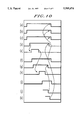
- FIG. 9 shows an example of an operating diagram of the control device during changeover of the blade pitch from forward thrust to reverse thrust positions.
- FIG. 10 shows an example of an operating diagram of the control device during changeover of the blade pitch from a take-off position to a cruising position.
- FIG. 1 is a partial axial section through the front of a turbojet engine comprising a control device in accordance with the invention for varying the pitch of the blades of a fan.
- the engine has a fan with a plurality of blades 1 mounted on a disc which is rotated by the engine main shaft 2.
- the shaft 2 is driven by a gas generator (not shown) by way of a speed reducer 3.
- Each fan blade has a root 4 pivotable around its longitudinal axis Z--Z' to vary the blade pitch.
- the control device for varying the rotor blade pitch has actuating means to change the blade pitch and means for locking the blade root in a predetermined position.
- FIGS. 1, 2a, 2b and 2c diagrammatically illustrate the actuating means for changing the blade pitch.
- This means comprises an electric motor having a stator winding 5 rigidly secured to the fixed structure 6 of the engine, and a rotor 7 rigidly secured to a toothed wheel 8 mounted on roller bearings and extending around the main shaft 2.
- the wheel 8 meshes with pinion sectors 9 which are secured to the root 4 of each blade 1, and enables the blades to be rotated around their longitudinal axis Z--Z'.
- the maximum angle of rotation of the assembly formed by a pinion 9, the toothed wheel 8 and the rotor 7 of the electric motor is defined by two fixed stops 10, 11 as shown diagrammatically in FIG. 2b. These two fixed stops correspond to operation of the engine in forward thrust and reverse thrust respectively. If one or more intermediate blade positions are required then movable stops 20, for example electromagnets, can be provided to supplement the fixed stops as shown in FIG. 2c.
- supplementary stops can be mounted on the angular path of a pinion sector 9 associated with a blade root 4 between the two fixed stops 10, 11. It is particularly advantageous to have three different angular positions available to give a blade a first position for take-off, a second position for cruising flight and a third position for thrust reversal.
- Each movable stop 20 can be formed by means of an electromagnet 12.
- the electromagnet is housed in a casing rigidly secured to the engine shaft 2, and comprises a winding in which a movable metal rod 22 can be displaced longitudinally by a magnetic field.
- a return spring 23 is disposed around the rod 22 so to retain it in its extended or end-of-travel position when the electromagnet 12 is in a de-activated state.
- the position of the movable stop 20 is monitored automatically and permanently by way of a position detector 24, for example of the end of stroke contact type.
- a movable stop for a predetermined intermediate position is preferably provided on a number of different blades. For example, and as FIG. 3 shows, three evenly spaced-apart blades may each have a movable stop for a predetermined intermediate position.
- a number of intermediate positions can be provided if a number of movable stops are placed at different angular positions relative to the pinion sectors 9.
- the movable stops situated at different angular positions relative to the pinion sectors need not necessarily be placed on the same blade root.
- the electromagnets 12 actuating the movable stops 20 can be powered without actual electrical contact by way of a rotary transformer.
- the electric motor used may be of the permanent magnet or asynchronous kind so as to eliminate friction and wear problems between the rotating part and the static part.
- the stator winding is stationary and is energized by alternating current (ac) using means which is known but not shown, for example an alternator or a generator associated with a rectifier and a thyratron inverter, so as to produce an alternating current at a controlled frequency.
- a permanent magnet rotor if provided, can, if required, comprise a closed circuit winding so as to increase motor power and reduce motor dimensions, the latter winding not being connected to the stator winding.
- the blade-locking means are shown diagrammatically in FIGS. 4a and 4b, and comprise an electromechanical actuator 13, for example an electromagnet, associated with a bolt 14 for retaining the blade roots 4 in a predetermined position.
- the blade roots are machined to have a number of surfaces corresponding to various possible predetermined positions.
- the actuator 13 comprises, in a casing rigidly secured to the engine shaft 2, a winding in which a metal rod 15 is movable longitudinally.
- the bolt 14 is rigidly secured to the rod 15, and when the rod 15 moves, it moves the bolt 14 with it.
- To retain the blade roots in a predetermined position the bolt 14 is formed with recesses 16 matching the blade roots. In the locked position the blade roots are locked in the recesses 16 in the bolt 14.
- the position of the bolt 14 is monitored automatically and permanently by way of a position detector 17, for example an end of stroke type of detector.
- the actuator 13 is powered without touching an electrical contact by way of a rotary transformer.
- FIG. 5 shows one embodiment of an electrical control and monitoring system for an electromechanical actuator for a control device in accordance with the invention.
- the actuator 13 is operated by way of a first rotary transformer 25 comprising a primary winding 18 rigidly secured to the fixed structure of the turbojet engine and a secondary winding 19 secured to the engine shaft 2.
- a first rotary transformer 25 comprising a primary winding 18 rigidly secured to the fixed structure of the turbojet engine and a secondary winding 19 secured to the engine shaft 2.
- the primary winding 18 is connected to a power supply device 26.
- the secondary winding 19 transmits the electrical power necessary to operate the actuator 13 by way of a rectifying diode bridge 27.
- the power for operating the actuator must be high enough to overcome its inertia and move the rod 15.
- the position of the rod 15 is signalled by a position detector 17, for example of the end of stroke kind, in the form of an electric switch, the position signal being transmitted to a position monitor 28 by way of a second rotary transformer 29.
- the second rotary transformer 29 comprises a primary winding 30 which is secured to the engine shaft 2 and is connected across the secondary winding 19 of the first transformer 25, and a secondary winding 31 which is connected across the input of the position monitor 28.
- the switch of the position detector 17 is in the closed state the second transformer 29 is energized by way of the first transformer 25 and transmits the energy received to the position monitor 28.
- This first example of an electrical device for operating and monitoring an electromechanical actuator is particularly suitable for an environment subject to heavy temperature stressing since it has very few electronic components.
- the presence of two rotary transformers has the disadvantage of increasing the weight and bulk of the blade-locking device.
- FIG. 6 shows a second example of an electrical device for operating and monitoring an electromechanical actuator of a control device in accordance with the invention.
- the actuator 13 is operated by way of a rotary transformer 32 comprising two independent sets of windings, each set comprising a primary winding and a secondary winding.
- the primary winding 33 and secondary winding 34 serve to transmit the electric power output of a supply device 26.
- This operates the actuator 13 and powers, by way of a position detector switch 17 such as an end of stroke detector, an oscillator 37 of high frequency f and low power relative to the frequency and power level of the power supply.
- the oscillator output signal is voltage-controlled by an internal voltage controller (not shown).
- the primary winding 35 and secondary winding 36 have only a few turns and serve to transmit to a position monitor 28 the signal delivered by the oscillator 37, the frequency f thereof representing the position of the actuator 13.
- This second embodiment of an electrical device for operating and monitoring the electromechanical actuator is compact and light since it has only a single rotary transformer, which simultaneously transmits, by way of independent sets of windings, electrical power from a fixed system to a rotating system and an electrical signal representing actuator position.
- the presence of the oscillator limits its use to environments in which the temperature variations lie within the operating range of the oscillator.
- the actuator is operated as follows.
- the rod 15 of the actuator 13 is in a limit position, and the switch which serves as position detector is open and no signal is transmitted to the monitor 28.
- the actuator 13 is electrically energized sufficiently to move the rod 15.
- a magnetic flux is produced in the winding of the actuator 13 and the rod 15 is moved by magnetic forces towards an unlocked position.
- the rod 15 operates the position detector 17 and closes its switch. An electrical signal is therefore transmitted to the position monitor 28.
- FIG. 7 shows a comparative example of the amplitude of the currents drawn by the actuator 13 during locked and unlocked periods.
- the position of the actuator rod 15 is monitored by the transmission of an electrical signal to a position monitor 28. Absence of the latter signal indicates a malfunctioning of the actuator 13.
- the position of the rod 15 is monitored by supplying the actuator 13 with an electrical signal of an amplitude smaller than is needed to move the rod 15. The absence of the signal from the position monitor 28 then indicates correct operation of the actuator.
- the actuators 12 of the movable stops 20 are operated in the same way as the blade-locking actuator 13.
- FIGS. 8a, 8b and 8c show three examples of rotary transformers which may be used in the control device of the invention.
- the rotary transformers comprise a fixed magnetic circuit 80 rigidly secured to the fixed structure of the turbojet engine and separated by axial air gaps 82, 83 from a rotary magnetic circuit 81 secured to the engine shaft 2.
- the rotary transformer comprises a set of windings consisting of a stationary primary winding 84 and a rotary secondary winding 85. This enables electrical power to be transmitted without mechanical contact from a stationary system to a rotating system.
- the rotary transformer comprises a first set of windings for the contactless transmission of electrical power from a stationary system to a rotating system, and a second set of windings which have just a few turns, for example one or two turns, which is independent of the first set of windings and which serve to transmit an electrical signal.
- FIG. 8c In the configuration of FIG. 8c three rotary transformers are shown. These are arranged one above another to form three independent sets of windings, the sets being magnetically insulated from one another. They can transmit three electrical signals independently of one another.
- two rotary transformers are necessary to power, on the one hand, the actuator 12 of the movable stops corresponding to a given intermediate position of the fan blades and, on the other hand, the actuator 13 of the blade-locking system.
- Each of these transformers comprises a set of windings for transmitting the power for operating the particular actuator concerned and a set of windings to transmit an electrical signal for monitoring the position of the rod of the particular actuator concerned.
- rotary transformers must be provided corresponding to the number of actuators of the respective movable stops.
- the pitch variation control device for the blades of a fan operates as follows.
- the speed reducer 3 drives the engine shaft 2 and the shaft 2 drives the bolt actuator 13 and the blades 1.
- the blades are kept stationary around their longitudinal axis by means of the bolt 14 positioned by the actuator 13.
- the blades 1 drive the toothed wheel 8 and the rotor 7 of the electric motor. There is no electrical energization of the stator winding of the electric motor.
- the position of the blades is altered to set them against another fixed or movable stop. It is particularly useful to have three blade positions available, two for two different forward thrust modes of operation and the third for reverse thrust operation.
- the two forward thrust modes may, for example, correspond to a take-off phase and a cruising phase, for which the blades are set against a first fixed end stop and against an intermediate movable stop respectively.
- the reverse thrust mode the blades are set against a second fixed end stop.
- the blade positions are altered on changeover from a forward thrust phase to a reverse thrust phase in accordance with the timing diagram shown in FIG. 9.
- the changeover from a forward thrust phase to a reverse thrust phase thus involves:
- FIG. 10 The timing diagram relating to the alteration in blade position for the changeover from a take-off phase to a cruising phase is shown in FIG. 10. It is similar to the diagram of FIG. 9 but is devoid of stages (g) and (k) of the method which respectively involve energizing and de-energizing the actuator 12 of the movable stop 20, since the latter must remain in position as it is the stop against which the blades have to be set.
- the method is similar for a return to a forward thrust position.
- the only modification concerns the speed of the rotating magnetic field and the direction of the magnetic torque produced thereby so that before the bolt is powered the blade roots are kept held against the stops corresponding to the reverse thrust position, and after the bolt is powered the blades are rotated from the reverse thrust position as far as the fixed stops corresponding to forward thrust.
- the electric motor needs to be powered for only a few seconds corresponding to the time taken to alter the position of the blades.
- an extra safety feature is provided for forcing the blades against a mechanical stop in the event of simultaneous failures of the locking system. This safety feature is provided by triggering the power supply to the electric motor when a problem of simultaneous failures is detected so as to produce a rotating magnetic field permanently forcing the blades against a mechanical stop.
- the locking system therefore has three safety levels, namely a bolt for locking the blades against rotation around their longitudinal axis, a movable stop preventing the blades from changing over from a forward thrust position to a reverse thrust position, and a rotating magnetic field for locking the blades in case of simultaneous failures of the bolt and movable stop.
- This invention is not limited to the embodiment hereinbefore described.
- the number of intermediate blade positions is not limited, and a number of movable stops each allocated to a different blade position can be provided.
- the locking system can be arranged to hold one or more blade roots depending on the reliability requirements.
Landscapes
- Engineering & Computer Science (AREA)
- Mechanical Engineering (AREA)
- General Engineering & Computer Science (AREA)
- Aviation & Aerospace Engineering (AREA)
- Structures Of Non-Positive Displacement Pumps (AREA)
Abstract
Description
Claims (28)
Priority Applications (1)
| Application Number | Priority Date | Filing Date | Title |
|---|---|---|---|
| US08/627,394 US5595474A (en) | 1993-11-10 | 1996-04-04 | Pitch variation control device for the blades of a turbomachine rotor and method of operating the device |
Applications Claiming Priority (4)
| Application Number | Priority Date | Filing Date | Title |
|---|---|---|---|
| FR9313409 | 1993-11-10 | ||
| FR9313409A FR2712250B1 (en) | 1993-11-10 | 1993-11-10 | Method and device for controlling the variation of the pitch of the blades of a rotor. |
| US33879894A | 1994-11-10 | 1994-11-10 | |
| US08/627,394 US5595474A (en) | 1993-11-10 | 1996-04-04 | Pitch variation control device for the blades of a turbomachine rotor and method of operating the device |
Related Parent Applications (1)
| Application Number | Title | Priority Date | Filing Date |
|---|---|---|---|
| US33879894A Continuation | 1993-11-10 | 1994-11-10 |
Publications (1)
| Publication Number | Publication Date |
|---|---|
| US5595474A true US5595474A (en) | 1997-01-21 |
Family
ID=9452718
Family Applications (1)
| Application Number | Title | Priority Date | Filing Date |
|---|---|---|---|
| US08/627,394 Expired - Fee Related US5595474A (en) | 1993-11-10 | 1996-04-04 | Pitch variation control device for the blades of a turbomachine rotor and method of operating the device |
Country Status (10)
| Country | Link |
|---|---|
| US (1) | US5595474A (en) |
| EP (1) | EP0652154B1 (en) |
| JP (1) | JP3032440B2 (en) |
| CA (1) | CA2135469C (en) |
| DE (1) | DE69411672T2 (en) |
| FR (1) | FR2712250B1 (en) |
| RU (1) | RU2107194C1 (en) |
| UA (1) | UA26462C2 (en) |
| WO (1) | WO1995013215A1 (en) |
| ZA (1) | ZA948876B (en) |
Cited By (47)
| Publication number | Priority date | Publication date | Assignee | Title |
|---|---|---|---|---|
| US6379109B1 (en) | 2000-05-12 | 2002-04-30 | Roy F. Senior, Jr. | Method and apparatus for detecting and removing obstructions in mechanical aerators |
| US6476534B1 (en) | 2000-08-08 | 2002-11-05 | General Dynamics Advanced Technology Systems, Inc. | Permanent magnet phase-control motor |
| US6672835B1 (en) | 2003-05-19 | 2004-01-06 | Arthur C. Hughes | Method and apparatus for self-contained variable pitch and/or constant speed propeller including provisions for feathering and reverse pitch operation |
| US20040052635A1 (en) * | 2000-11-14 | 2004-03-18 | Aloys Wobben | Wind energy turbine |
| US20050226727A1 (en) * | 2004-03-03 | 2005-10-13 | Dennis Brian D | Methods and systems for controlling the pitch of a propeller |
| US20080273976A1 (en) * | 2007-02-21 | 2008-11-06 | United Technologies Corporation | Variable rotor blade for gas turbine engine |
| US20090180915A1 (en) * | 2004-12-16 | 2009-07-16 | Tdy Industries, Inc. | Methods of making cemented carbide inserts for earth-boring bits |
| US20110169270A1 (en) * | 2007-06-01 | 2011-07-14 | Bill Todorof | Direct drive wind turbine and blade assembly |
| US20120055137A1 (en) * | 2009-02-27 | 2012-03-08 | Snecma | Fan blades with cyclic setting |
| US20120070289A1 (en) * | 2010-09-20 | 2012-03-22 | Snecma | Bellows type sealing device for partition penetration by a connecting rod of a turboprop fan blade orientation control system |
| US20120207598A1 (en) * | 2009-10-22 | 2012-08-16 | Snecma | System for varying the angle of attack of the blades of an aircraft turbine engine propeller, using a brushless electric motor |
| US20130047756A1 (en) * | 2010-03-01 | 2013-02-28 | Snecma | Counterweight-based device for controlling the orientation of fan blades of a turboprop engine |
| US20130058789A1 (en) * | 2010-04-30 | 2013-03-07 | Hispano-Suiza | Actuating blades of an unducted fan |
| US20130086922A1 (en) * | 2011-10-05 | 2013-04-11 | Pratt & Whitney | Combined Pump System for Engine TMS AOC Reduction and ECS Loss Elimination |
| WO2013076431A1 (en) * | 2011-11-24 | 2013-05-30 | Hispano Suiza | Rotary mechanical system with contactless actuation |
| US20130142653A1 (en) * | 2010-08-17 | 2013-06-06 | Siemens Aktiengesellschaft | Variable-pitch propeller or repeller |
| US20130280078A1 (en) * | 2012-04-23 | 2013-10-24 | Kollmorgen Corporation | Wind Turbine Blade Pitch Redundant Safety Arrangement |
| US20160229547A1 (en) * | 2013-10-11 | 2016-08-11 | Unison Industries, Llc | Method and apparatus for controlling a turboprop engine |
| US20170276014A1 (en) * | 2016-03-24 | 2017-09-28 | United Technologies Corporation | Variable vane actuation with rotating ring and sliding links |
| US20170276148A1 (en) * | 2016-03-24 | 2017-09-28 | United Technologies Corporation | Off-axis electric actuation for variable vanes |
| US20170276015A1 (en) * | 2016-03-24 | 2017-09-28 | United Technologies Corporation | Sliding gear actuation for variable vanes |
| US20170276016A1 (en) * | 2016-03-24 | 2017-09-28 | United Technologies Corporation | Idler gear connection for multi-stage variable vane actuation |
| CN107902075A (en) * | 2017-11-09 | 2018-04-13 | 中国航发湖南动力机械研究所 | Static variable-pitch propeller |
| US10190599B2 (en) | 2016-03-24 | 2019-01-29 | United Technologies Corporation | Drive shaft for remote variable vane actuation |
| WO2019040490A1 (en) * | 2017-08-23 | 2019-02-28 | Vimaan Robotics, Inc. | A drive mechanism |
| US10287908B2 (en) * | 2016-08-12 | 2019-05-14 | Safran Aero Boosters Sa | Variable orientation vane for compressor of axial turbomachine |
| US10294813B2 (en) | 2016-03-24 | 2019-05-21 | United Technologies Corporation | Geared unison ring for variable vane actuation |
| US10301962B2 (en) | 2016-03-24 | 2019-05-28 | United Technologies Corporation | Harmonic drive for shaft driving multiple stages of vanes via gears |
| US10329947B2 (en) | 2016-03-24 | 2019-06-25 | United Technologies Corporation | 35Geared unison ring for multi-stage variable vane actuation |
| US10415596B2 (en) | 2016-03-24 | 2019-09-17 | United Technologies Corporation | Electric actuation for variable vanes |
| US10436056B2 (en) | 2015-06-23 | 2019-10-08 | General Electric Company | Relative position measurement |
| US10458271B2 (en) | 2016-03-24 | 2019-10-29 | United Technologies Corporation | Cable drive system for variable vane operation |
| US20200095876A1 (en) * | 2016-01-05 | 2020-03-26 | Safran Aircraft Engines | Low-pitch variable-setting fan of a turbine engine |
| US10801339B2 (en) | 2017-07-11 | 2020-10-13 | General Electric Company | Aircraft gas turbine engine variable fan blade mechanism |
| US10934880B1 (en) | 2019-09-04 | 2021-03-02 | The Boeing Company | Electrical generation from turbine engines |
| CN112823245A (en) * | 2018-10-12 | 2021-05-18 | 赛峰飞机发动机公司 | Turbine engine including a rotor with pitched blades |
| AT523262A4 (en) * | 2020-01-29 | 2021-07-15 | Manuel Schleiffelder Mag | Device for adjusting the inclination of the rotor blades of a rotor |
| CN113682462A (en) * | 2021-09-18 | 2021-11-23 | 上海交通大学 | Propulsion unit and electric drive ducted fan propulsion system with adjustable inlet pre-rotation guide vanes |
| US11193426B2 (en) | 2020-04-16 | 2021-12-07 | The Boeing Company | Electrically geared turbofan |
| EP3957829A1 (en) * | 2020-08-20 | 2022-02-23 | General Electric Company Polska Sp. Z o.o | Propulsion engine assemblies providing access to components within propulsor cavities |
| US11345469B2 (en) * | 2018-11-19 | 2022-05-31 | Joby Aero, Inc. | Aerial vehicle using motor pulse-induced cyclic control |
| US11362567B2 (en) | 2020-01-16 | 2022-06-14 | The Boeing Company | Electrical power generation from turbine engines |
| US11365690B2 (en) | 2017-12-19 | 2022-06-21 | Siemens Energy Global GmbH & Co. KG | Compressor control |
| CN115123519A (en) * | 2022-08-30 | 2022-09-30 | 沃飞长空科技(成都)有限公司 | Variable-pitch rotor wing device and aircraft |
| US11667374B2 (en) | 2020-03-16 | 2023-06-06 | Ratier-Figeac Sas | Blade pitch actuation mechanism |
| US20240322646A1 (en) * | 2023-03-24 | 2024-09-26 | Rolls-Royce North American Technologies, Inc. | Electric generator behind fan in turbine engine |
| US12152539B2 (en) | 2020-12-10 | 2024-11-26 | The Boeing Company | Direct drive electrically-geared turbofan |
Families Citing this family (19)
| Publication number | Priority date | Publication date | Assignee | Title |
|---|---|---|---|---|
| DE4446623A1 (en) * | 1994-12-24 | 1996-06-27 | Klein Schanzlin & Becker Ag | Propeller adjustment device with synchronous element |
| RU2108268C1 (en) * | 1996-10-17 | 1998-04-10 | Йелстаун Корпорейшн Н.В. | System and method of control of variable-pitch propeller with feedback |
| WO2003035470A1 (en) * | 2001-10-22 | 2003-05-01 | Lamont John S | Aircraft |
| FR2831225B1 (en) | 2001-10-24 | 2004-01-02 | Snecma Moteurs | ELECTROHYDRAULIC DEVICE FOR CHANGING PROPELLER PITCH |
| CA2459200A1 (en) | 2004-02-27 | 2005-08-27 | John S. Lamont | Aircraft |
| FR2922265B1 (en) * | 2007-10-12 | 2013-11-22 | Snecma | TURBOREACTOR INCORPORATING AN ELECTRIC CURRENT GENERATOR. |
| RU2390659C1 (en) * | 2008-12-22 | 2010-05-27 | Государственное образовательное учреждение высшего профессионального образования "Воронежский государственный технический университет" | Device for changing setting angles of rotating blades of fan |
| FR2961176B1 (en) * | 2010-06-15 | 2012-08-03 | Hispano Suiza Sa | ELECTRICAL SUPPLY OF EQUIPMENT FITTED BY THE ROTOR OF AN AIRCRAFT ENGINE |
| RU2479753C2 (en) * | 2011-07-07 | 2013-04-20 | Общество с ограниченной ответственностью "Газхолодтехника" | Method of automatic control over blower impeller rpm |
| ITTO20111113A1 (en) * | 2011-12-05 | 2013-06-06 | Wilic Sarl | WIND POWER PLANT FOR THE GENERATION OF ELECTRICITY |
| FR2997245B1 (en) * | 2012-10-24 | 2016-01-15 | Hispano Suiza Sa | ELECTROMECHANICAL ACTUATION AND / OR GENERATION SYSTEM COMPRISING AN ELECTRICAL INSULATION BETWEEN THE ELECTRIC SOURCE AND THE CONSUMER |
| CN104863881B (en) * | 2014-02-21 | 2018-10-23 | 南京中兴新软件有限责任公司 | The control method and device of rotation speed of the fan in electronic equipment |
| US10436151B2 (en) * | 2015-11-17 | 2019-10-08 | General Electric Company | Modular fan for a gas turbine engine |
| FR3075257B1 (en) * | 2017-12-14 | 2021-02-19 | Safran Aircraft Engines | PROPELLER TIMING ADJUSTMENT DEVICE |
| CN113007133A (en) * | 2019-12-19 | 2021-06-22 | 北汽福田汽车股份有限公司 | Fan, heat dissipation module and vehicle |
| FR3108670B1 (en) | 2020-03-31 | 2022-04-01 | Safran Aircraft Engines | FAN MODULE FOR AN AIRCRAFT TURBOMACHINE TEST BENCH |
| US20210347465A1 (en) * | 2020-05-11 | 2021-11-11 | Hamilton Sundstrand Corporation | Wireless power transformation for rotating propellers |
| WO2022116398A1 (en) * | 2021-02-20 | 2022-06-09 | 西安亚能电气有限责任公司 | Monitoring assembly, monitoring apparatus, and monitoring module for fan in electrical power system |
| CN113955084B (en) * | 2021-12-22 | 2022-03-25 | 四川承天翼航空科技有限公司 | Rotor wing variable-pitch control system and method and synchronous/asynchronous variable-pitch control method |
Citations (13)
| Publication number | Priority date | Publication date | Assignee | Title |
|---|---|---|---|---|
| FR890641A (en) * | 1942-10-05 | 1944-02-14 | System for the transmission of electrical energy between a fixed part and a moving part, mechanisms and machines comprising application of this system | |
| US2370135A (en) * | 1941-09-25 | 1945-02-27 | Engineering & Res Corp | Variable pitch propeller |
| US2612228A (en) * | 1945-07-03 | 1952-09-30 | Fairey Aviat Co Ltd | Electrically driven propeller pitch change system |
| US2632516A (en) * | 1946-11-26 | 1953-03-24 | United Aircraft Corp | Automatic control for reversing propellers |
| US3044558A (en) * | 1960-01-05 | 1962-07-17 | Curtiss Wright Corp | Propeller pitch control system |
| US3900274A (en) * | 1974-06-25 | 1975-08-19 | Gen Electric | Remote controlled actuation system for the rotor of a gas turbine engine |
| US4591313A (en) * | 1983-12-30 | 1986-05-27 | The Boeing Company | Propeller pitch control system and apparatus |
| US5183387A (en) * | 1992-01-03 | 1993-02-02 | Allied-Signal, Inc. | Fault-tolerant apparatus for controlling blade pitch |
| US5205712A (en) * | 1991-05-13 | 1993-04-27 | Allied-Signal Inc. | Variable pitch fan gas turbine engine |
| US5281094A (en) * | 1991-05-13 | 1994-01-25 | Alliedsignal Inc | Electromechanical apparatus for varying blade of variable-pitch fan blades |
| US5282719A (en) * | 1991-05-13 | 1994-02-01 | Alliedsignal Inc. | Quad mode fan pitch actuation system for a gas turbine engine |
| US5451141A (en) * | 1993-12-23 | 1995-09-19 | United Technologies Corporation | Propeller pitch change machanism with inductive brake and motor |
| US5451856A (en) * | 1993-07-28 | 1995-09-19 | Societe Hispano Suiza | Device for the transmission of electrical power signals to a rotary assembly |
-
1993
- 1993-11-10 FR FR9313409A patent/FR2712250B1/en not_active Expired - Fee Related
-
1994
- 1994-11-09 EP EP94402530A patent/EP0652154B1/en not_active Expired - Lifetime
- 1994-11-09 UA UA95073144A patent/UA26462C2/en unknown
- 1994-11-09 DE DE69411672T patent/DE69411672T2/en not_active Expired - Fee Related
- 1994-11-09 RU RU95121938A patent/RU2107194C1/en not_active IP Right Cessation
- 1994-11-09 ZA ZA948876A patent/ZA948876B/en unknown
- 1994-11-09 WO PCT/FR1994/001308 patent/WO1995013215A1/en not_active Ceased
- 1994-11-09 CA CA002135469A patent/CA2135469C/en not_active Expired - Fee Related
- 1994-11-10 JP JP6303020A patent/JP3032440B2/en not_active Expired - Fee Related
-
1996
- 1996-04-04 US US08/627,394 patent/US5595474A/en not_active Expired - Fee Related
Patent Citations (13)
| Publication number | Priority date | Publication date | Assignee | Title |
|---|---|---|---|---|
| US2370135A (en) * | 1941-09-25 | 1945-02-27 | Engineering & Res Corp | Variable pitch propeller |
| FR890641A (en) * | 1942-10-05 | 1944-02-14 | System for the transmission of electrical energy between a fixed part and a moving part, mechanisms and machines comprising application of this system | |
| US2612228A (en) * | 1945-07-03 | 1952-09-30 | Fairey Aviat Co Ltd | Electrically driven propeller pitch change system |
| US2632516A (en) * | 1946-11-26 | 1953-03-24 | United Aircraft Corp | Automatic control for reversing propellers |
| US3044558A (en) * | 1960-01-05 | 1962-07-17 | Curtiss Wright Corp | Propeller pitch control system |
| US3900274A (en) * | 1974-06-25 | 1975-08-19 | Gen Electric | Remote controlled actuation system for the rotor of a gas turbine engine |
| US4591313A (en) * | 1983-12-30 | 1986-05-27 | The Boeing Company | Propeller pitch control system and apparatus |
| US5205712A (en) * | 1991-05-13 | 1993-04-27 | Allied-Signal Inc. | Variable pitch fan gas turbine engine |
| US5281094A (en) * | 1991-05-13 | 1994-01-25 | Alliedsignal Inc | Electromechanical apparatus for varying blade of variable-pitch fan blades |
| US5282719A (en) * | 1991-05-13 | 1994-02-01 | Alliedsignal Inc. | Quad mode fan pitch actuation system for a gas turbine engine |
| US5183387A (en) * | 1992-01-03 | 1993-02-02 | Allied-Signal, Inc. | Fault-tolerant apparatus for controlling blade pitch |
| US5451856A (en) * | 1993-07-28 | 1995-09-19 | Societe Hispano Suiza | Device for the transmission of electrical power signals to a rotary assembly |
| US5451141A (en) * | 1993-12-23 | 1995-09-19 | United Technologies Corporation | Propeller pitch change machanism with inductive brake and motor |
Cited By (82)
| Publication number | Priority date | Publication date | Assignee | Title |
|---|---|---|---|---|
| US6379109B1 (en) | 2000-05-12 | 2002-04-30 | Roy F. Senior, Jr. | Method and apparatus for detecting and removing obstructions in mechanical aerators |
| US6476534B1 (en) | 2000-08-08 | 2002-11-05 | General Dynamics Advanced Technology Systems, Inc. | Permanent magnet phase-control motor |
| US20040052635A1 (en) * | 2000-11-14 | 2004-03-18 | Aloys Wobben | Wind energy turbine |
| US6939103B2 (en) * | 2000-11-14 | 2005-09-06 | Aloys Wobben | Wind power installation with multiple blade adjusting devices |
| US6672835B1 (en) | 2003-05-19 | 2004-01-06 | Arthur C. Hughes | Method and apparatus for self-contained variable pitch and/or constant speed propeller including provisions for feathering and reverse pitch operation |
| US20050226727A1 (en) * | 2004-03-03 | 2005-10-13 | Dennis Brian D | Methods and systems for controlling the pitch of a propeller |
| WO2005084373A3 (en) * | 2004-03-03 | 2009-03-26 | Insitu Group Inc | Methods and systems for controlling the pitch of a propeller |
| US20090180915A1 (en) * | 2004-12-16 | 2009-07-16 | Tdy Industries, Inc. | Methods of making cemented carbide inserts for earth-boring bits |
| US20080273976A1 (en) * | 2007-02-21 | 2008-11-06 | United Technologies Corporation | Variable rotor blade for gas turbine engine |
| US7901185B2 (en) * | 2007-02-21 | 2011-03-08 | United Technologies Corporation | Variable rotor blade for gas turbine engine |
| US8269369B2 (en) * | 2007-06-01 | 2012-09-18 | Bill Todorof | Direct drive wind turbine and blade assembly |
| US20110169270A1 (en) * | 2007-06-01 | 2011-07-14 | Bill Todorof | Direct drive wind turbine and blade assembly |
| US9200594B2 (en) * | 2009-02-27 | 2015-12-01 | Snecma | Gas turbine engine having fan blades of adjustable pitch with cyclic setting |
| US20120055137A1 (en) * | 2009-02-27 | 2012-03-08 | Snecma | Fan blades with cyclic setting |
| US20120207598A1 (en) * | 2009-10-22 | 2012-08-16 | Snecma | System for varying the angle of attack of the blades of an aircraft turbine engine propeller, using a brushless electric motor |
| US8979496B2 (en) * | 2009-10-22 | 2015-03-17 | Snecma | System for varying the angle of attack of the blades of an aircraft turbine engine propeller, using a brushless electric motor |
| US20130047756A1 (en) * | 2010-03-01 | 2013-02-28 | Snecma | Counterweight-based device for controlling the orientation of fan blades of a turboprop engine |
| US8932018B2 (en) * | 2010-03-01 | 2015-01-13 | Snecma | Counterweight-based device for controlling the orientation of fan blades of a turboprop engine |
| US20130058789A1 (en) * | 2010-04-30 | 2013-03-07 | Hispano-Suiza | Actuating blades of an unducted fan |
| US9073626B2 (en) * | 2010-04-30 | 2015-07-07 | Labinal Power Systems | Actuating blades of an unducted fan |
| US9476311B2 (en) * | 2010-08-17 | 2016-10-25 | Siemens Aktiengesellschaft | Variable-pitch propeller or repeller |
| US20130142653A1 (en) * | 2010-08-17 | 2013-06-06 | Siemens Aktiengesellschaft | Variable-pitch propeller or repeller |
| US8944765B2 (en) * | 2010-09-20 | 2015-02-03 | Snecma | Bellows type sealing device for partition penetration by a connecting rod of a turboprop fan blade orientation control system |
| US20120070289A1 (en) * | 2010-09-20 | 2012-03-22 | Snecma | Bellows type sealing device for partition penetration by a connecting rod of a turboprop fan blade orientation control system |
| US20130086922A1 (en) * | 2011-10-05 | 2013-04-11 | Pratt & Whitney | Combined Pump System for Engine TMS AOC Reduction and ECS Loss Elimination |
| US9470153B2 (en) * | 2011-10-05 | 2016-10-18 | United Technologies Corporation | Combined pump system for engine TMS AOC reduction and ECS loss elimination |
| FR2983235A1 (en) * | 2011-11-24 | 2013-05-31 | Hispano Suiza Sa | ROTATING MECHANICAL SYSTEM WITH CONTACTLESS ACTUATION |
| CN103958346B (en) * | 2011-11-24 | 2016-08-17 | 雷比诺电力系统 | Rotating mechanical system with contactless actuation and aircraft turbine engine including the same |
| WO2013076431A1 (en) * | 2011-11-24 | 2013-05-30 | Hispano Suiza | Rotary mechanical system with contactless actuation |
| CN103958346A (en) * | 2011-11-24 | 2014-07-30 | 伊斯帕诺-絮扎公司 | Rotary mechanical system with contactless actuation |
| US20140322017A1 (en) * | 2011-11-24 | 2014-10-30 | Hispano Suiza | Rotary mechanical system with contactless actuation |
| US20130280078A1 (en) * | 2012-04-23 | 2013-10-24 | Kollmorgen Corporation | Wind Turbine Blade Pitch Redundant Safety Arrangement |
| WO2013162920A1 (en) * | 2012-04-23 | 2013-10-31 | Kollmorgen Corporation | Wind turbine blade pitch redundant safety arrangement |
| ES2529516R1 (en) * | 2012-04-23 | 2015-05-04 | Kollmorgen Corporation | Redundant safety provision of wind turbine blades |
| US20160229547A1 (en) * | 2013-10-11 | 2016-08-11 | Unison Industries, Llc | Method and apparatus for controlling a turboprop engine |
| US9932120B2 (en) * | 2013-10-11 | 2018-04-03 | Unison Industries, Llc | Method and apparatus for controlling a turboprop engine |
| US11156119B2 (en) | 2015-06-23 | 2021-10-26 | General Electric Company | Relative position measurement |
| US10436056B2 (en) | 2015-06-23 | 2019-10-08 | General Electric Company | Relative position measurement |
| US10830066B2 (en) * | 2016-01-05 | 2020-11-10 | Safran Aircraft Engines | Low-pitch variable-setting fan of a turbine engine |
| US20200095876A1 (en) * | 2016-01-05 | 2020-03-26 | Safran Aircraft Engines | Low-pitch variable-setting fan of a turbine engine |
| US10190599B2 (en) | 2016-03-24 | 2019-01-29 | United Technologies Corporation | Drive shaft for remote variable vane actuation |
| US10443431B2 (en) * | 2016-03-24 | 2019-10-15 | United Technologies Corporation | Idler gear connection for multi-stage variable vane actuation |
| US20170276014A1 (en) * | 2016-03-24 | 2017-09-28 | United Technologies Corporation | Variable vane actuation with rotating ring and sliding links |
| US20170276148A1 (en) * | 2016-03-24 | 2017-09-28 | United Technologies Corporation | Off-axis electric actuation for variable vanes |
| US10288087B2 (en) * | 2016-03-24 | 2019-05-14 | United Technologies Corporation | Off-axis electric actuation for variable vanes |
| US10294813B2 (en) | 2016-03-24 | 2019-05-21 | United Technologies Corporation | Geared unison ring for variable vane actuation |
| US10301962B2 (en) | 2016-03-24 | 2019-05-28 | United Technologies Corporation | Harmonic drive for shaft driving multiple stages of vanes via gears |
| US10329947B2 (en) | 2016-03-24 | 2019-06-25 | United Technologies Corporation | 35Geared unison ring for multi-stage variable vane actuation |
| US10329946B2 (en) * | 2016-03-24 | 2019-06-25 | United Technologies Corporation | Sliding gear actuation for variable vanes |
| US10415596B2 (en) | 2016-03-24 | 2019-09-17 | United Technologies Corporation | Electric actuation for variable vanes |
| US20170276016A1 (en) * | 2016-03-24 | 2017-09-28 | United Technologies Corporation | Idler gear connection for multi-stage variable vane actuation |
| US11131323B2 (en) | 2016-03-24 | 2021-09-28 | Raytheon Technologies Corporation | Harmonic drive for shaft driving multiple stages of vanes via gears |
| US10443430B2 (en) * | 2016-03-24 | 2019-10-15 | United Technologies Corporation | Variable vane actuation with rotating ring and sliding links |
| US10458271B2 (en) | 2016-03-24 | 2019-10-29 | United Technologies Corporation | Cable drive system for variable vane operation |
| US20170276015A1 (en) * | 2016-03-24 | 2017-09-28 | United Technologies Corporation | Sliding gear actuation for variable vanes |
| US10287908B2 (en) * | 2016-08-12 | 2019-05-14 | Safran Aero Boosters Sa | Variable orientation vane for compressor of axial turbomachine |
| US10801339B2 (en) | 2017-07-11 | 2020-10-13 | General Electric Company | Aircraft gas turbine engine variable fan blade mechanism |
| CN111065577A (en) * | 2017-08-23 | 2020-04-24 | 维曼机器人股份有限公司 | Drive mechanism |
| WO2019040490A1 (en) * | 2017-08-23 | 2019-02-28 | Vimaan Robotics, Inc. | A drive mechanism |
| CN107902075B (en) * | 2017-11-09 | 2020-11-27 | 中国航发湖南动力机械研究所 | Static variable pitch propeller |
| CN107902075A (en) * | 2017-11-09 | 2018-04-13 | 中国航发湖南动力机械研究所 | Static variable-pitch propeller |
| US11365690B2 (en) | 2017-12-19 | 2022-06-21 | Siemens Energy Global GmbH & Co. KG | Compressor control |
| CN112823245A (en) * | 2018-10-12 | 2021-05-18 | 赛峰飞机发动机公司 | Turbine engine including a rotor with pitched blades |
| CN112823245B (en) * | 2018-10-12 | 2024-03-08 | 赛峰飞机发动机公司 | Turbine engine including rotor with pitch blades |
| US11719107B2 (en) | 2018-10-12 | 2023-08-08 | Safran Aircraft Engines | Turbine engine comprising a rotor with variable-pitch blades |
| US11345469B2 (en) * | 2018-11-19 | 2022-05-31 | Joby Aero, Inc. | Aerial vehicle using motor pulse-induced cyclic control |
| EP3789598A1 (en) * | 2019-09-04 | 2021-03-10 | The Boeing Company | Electrical generation from turbine engines |
| US10934880B1 (en) | 2019-09-04 | 2021-03-02 | The Boeing Company | Electrical generation from turbine engines |
| US11362567B2 (en) | 2020-01-16 | 2022-06-14 | The Boeing Company | Electrical power generation from turbine engines |
| AT523262B1 (en) * | 2020-01-29 | 2021-07-15 | Manuel Schleiffelder Mag | Device for adjusting the inclination of the rotor blades of a rotor |
| AT523262A4 (en) * | 2020-01-29 | 2021-07-15 | Manuel Schleiffelder Mag | Device for adjusting the inclination of the rotor blades of a rotor |
| US11667374B2 (en) | 2020-03-16 | 2023-06-06 | Ratier-Figeac Sas | Blade pitch actuation mechanism |
| US11193426B2 (en) | 2020-04-16 | 2021-12-07 | The Boeing Company | Electrically geared turbofan |
| US11643973B2 (en) | 2020-04-16 | 2023-05-09 | The Boeing Company | Electrically geared turbofan |
| EP3957829A1 (en) * | 2020-08-20 | 2022-02-23 | General Electric Company Polska Sp. Z o.o | Propulsion engine assemblies providing access to components within propulsor cavities |
| US12122529B2 (en) | 2020-08-20 | 2024-10-22 | General Electric Company Polska sp. z o.o | Propulsion engine assemblies providing access to components within propulsor cavities |
| US12152539B2 (en) | 2020-12-10 | 2024-11-26 | The Boeing Company | Direct drive electrically-geared turbofan |
| CN113682462A (en) * | 2021-09-18 | 2021-11-23 | 上海交通大学 | Propulsion unit and electric drive ducted fan propulsion system with adjustable inlet pre-rotation guide vanes |
| CN115123519B (en) * | 2022-08-30 | 2022-11-22 | 沃飞长空科技(成都)有限公司 | Variable-pitch rotor wing device and aircraft |
| CN115123519A (en) * | 2022-08-30 | 2022-09-30 | 沃飞长空科技(成都)有限公司 | Variable-pitch rotor wing device and aircraft |
| US20240322646A1 (en) * | 2023-03-24 | 2024-09-26 | Rolls-Royce North American Technologies, Inc. | Electric generator behind fan in turbine engine |
| US12388322B2 (en) * | 2023-03-24 | 2025-08-12 | Rolls-Royce North American Technologies, Inc. | Electric generator behind fan in turbine engine |
Also Published As
| Publication number | Publication date |
|---|---|
| CA2135469A1 (en) | 1995-05-11 |
| WO1995013215A1 (en) | 1995-05-18 |
| UA26462C2 (en) | 1999-08-30 |
| DE69411672T2 (en) | 1998-12-24 |
| FR2712250A1 (en) | 1995-05-19 |
| EP0652154B1 (en) | 1998-07-15 |
| JPH07197852A (en) | 1995-08-01 |
| FR2712250B1 (en) | 1995-12-29 |
| RU2107194C1 (en) | 1998-03-20 |
| DE69411672D1 (en) | 1998-08-20 |
| EP0652154A1 (en) | 1995-05-10 |
| JP3032440B2 (en) | 2000-04-17 |
| CA2135469C (en) | 2003-04-22 |
| ZA948876B (en) | 1995-07-31 |
Similar Documents
| Publication | Publication Date | Title |
|---|---|---|
| US5595474A (en) | Pitch variation control device for the blades of a turbomachine rotor and method of operating the device | |
| US5282719A (en) | Quad mode fan pitch actuation system for a gas turbine engine | |
| US5300848A (en) | Dual permanent magnet generator planetary gear actuator and rotor phase shifting method | |
| CA1231132A (en) | Propeller actuation system | |
| US6767187B2 (en) | Electrohydraulic device for varying the pitch of the blades of a machine rotor | |
| US3900274A (en) | Remote controlled actuation system for the rotor of a gas turbine engine | |
| US5309029A (en) | Aircraft power unit with elective mechanical coupling | |
| EP0453179A2 (en) | Electromagnetic damping of shaft motion | |
| US6325331B1 (en) | Trim actuator | |
| US5451141A (en) | Propeller pitch change machanism with inductive brake and motor | |
| US10663041B2 (en) | Jam-tolerant electric linear actuator | |
| RU95121938A (en) | DEVICE FOR ADJUSTING CHANGE OF STEP OF TURBO ROTOR ROTOR BLADES AND METHOD FOR REGULATING CONTROL OF CHANGE OF STEP OF TURBO ROTOR ROTOR BLADES | |
| CA2995217C (en) | Engine shaft integrated motor | |
| US10870481B2 (en) | Pitch actuation system for a turbomachine propeller | |
| US10633987B2 (en) | Simplified pitch actuation system for a turbine engine propeller | |
| JPS63159627A (en) | Differential type power device for multiple spool type turbine engine | |
| EP3223413B1 (en) | Axial flux permanent magnet machine | |
| US10766604B2 (en) | System for electromechanical pitch actuation for a turbine engine propeller | |
| CN109690027B (en) | Device for controlling inlet guide vane by multilayer piezoelectric actuator | |
| US10780976B2 (en) | Simplified pitch actuation system for a turbomachine propeller | |
| US10647411B2 (en) | Electromechanical pitch actuation system for a turbomachine propeller | |
| EP4462655A1 (en) | Electrical energy system having active segments for variable voltage generation | |
| US2816975A (en) | Torsion oscillator mechanical switch | |
| SU1642556A1 (en) | Electric machine with controlled excitation | |
| Ellis et al. | Common drive unit |
Legal Events
| Date | Code | Title | Description |
|---|---|---|---|
| CC | Certificate of correction | ||
| FEPP | Fee payment procedure |
Free format text: PAYOR NUMBER ASSIGNED (ORIGINAL EVENT CODE: ASPN); ENTITY STATUS OF PATENT OWNER: LARGE ENTITY |
|
| FPAY | Fee payment |
Year of fee payment: 4 |
|
| FEPP | Fee payment procedure |
Free format text: PAYER NUMBER DE-ASSIGNED (ORIGINAL EVENT CODE: RMPN); ENTITY STATUS OF PATENT OWNER: LARGE ENTITY Free format text: PAYOR NUMBER ASSIGNED (ORIGINAL EVENT CODE: ASPN); ENTITY STATUS OF PATENT OWNER: LARGE ENTITY |
|
| FPAY | Fee payment |
Year of fee payment: 8 |
|
| REMI | Maintenance fee reminder mailed | ||
| LAPS | Lapse for failure to pay maintenance fees | ||
| STCH | Information on status: patent discontinuation |
Free format text: PATENT EXPIRED DUE TO NONPAYMENT OF MAINTENANCE FEES UNDER 37 CFR 1.362 |
|
| FP | Lapsed due to failure to pay maintenance fee |
Effective date: 20090121 |