US558564A - Electric-alarm system - Google Patents
Electric-alarm system Download PDFInfo
- Publication number
- US558564A US558564A US558564DA US558564A US 558564 A US558564 A US 558564A US 558564D A US558564D A US 558564DA US 558564 A US558564 A US 558564A
- Authority
- US
- United States
- Prior art keywords
- alarm
- circuit
- auxiliary
- galvanometer
- house
- Prior art date
- Legal status (The legal status is an assumption and is not a legal conclusion. Google has not performed a legal analysis and makes no representation as to the accuracy of the status listed.)
- Expired - Lifetime
Links
Images

Classifications
-
- G—PHYSICS
- G08—SIGNALLING
- G08B—SIGNALLING SYSTEMS, e.g. PERSONAL CALLING SYSTEMS; ORDER TELEGRAPHS; ALARM SYSTEMS
- G08B25/00—Alarm systems in which the location of the alarm condition is signalled to a central station, e.g. fire or police telegraphic systems
- G08B25/12—Manually actuated calamity alarm transmitting arrangements emergency non-personal manually actuated alarm, activators, e.g. details of alarm push buttons mounted on an infrastructure
Definitions
- a fire-alarm system comprising means whereby the signal-transmitting mechanism of a street-box can be started by a person within a neighboring building.
- Said system comprises a magnetoreleasing device for liberating the signaltransmitting mechanism, and a normallyclosed auxiliary or house circuit, which includes a local or house alarm, a local battery, and one or more supplemental sources of electric energy preferably consisting ⁇ of one or more magneto-generators.
- Said battery is not of sufficient strength to operate the means employed for releasing the signal-transmitting mechanism, although said means will be subject to the battery.
- the means employed for releasing the signal-transmitting mechanism although said means will be subject to the battery.
- it will only be necessary for a person within the building to slightly operate the magneto-electric generator, whereupon an impulse of high electromotive force will be sent over the normally-closed circuit, and this, as auxiliary or supplemental to the local battery, will actuate the means employed for releasing the signaltransmitting mechanism, and thereby cause the releasement of the latter.
- the signal-transmitting mechanism will start up, and while sending in signals over the main line to the nre-department will also repeat back to the local orhouse alarm, whereby local notication will be made of the fact that the signal-transmitting mechanism is in order and properly working.
- the converse of said act can be employed for the purpose of again placing the alarm in condition for operation, and if at such time the signal-transmitting mechanism should be wound up and set the alarm will remain inactive,while,on the other hand, should the auxiliary circuit be open, either ⁇ as a result of accidental rupture or by reason .of an omission to wind up and set the signal-transmitting mechanism, the local alarm will sound and give notice of such fact; also, should the local battery give out, or should the line of the auxiliary circuit be broken by any cause whatsoever, the local or house alarm will sound and thereby give notice that the system needs attention. Ihen the signal-transmitting mechanism is manually started, all local or house alarms in the local system will sound, thereby giving local notice of the existence of a fire.
- the object of my invention is to improve such system by providing a further alarm device whereby in case of any disarrangement of the circuit, such as by the taking out or adding a resistance to any portion thereof, the alarm will give notice of such fact, a further object being to adapt such alarm for any alarm-circuit wherein its presence may be of service.
- I provide the house or other auxiliary or alarm circuit with a bridge and galvanometer and arrange in conjunction with the galvanometer an alarm which is governed by the deflection of the galvanometer-needle, as hereinafter more fully set forth.
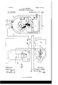
- Figure l represents my improvement as applied to the system of my said application.
- Fig. 2 further illustrates suchsystem and illustrates more fully one of the magneto-generators and the signal-transmitting mechanism.
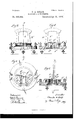
- Fig. 3 showsthe galvanometer in side elevation on a larger scale.
- Fig. 4 is a section on line a'. in Fig. 6.
- Fig. 5 is a top plan view.
- Fig. 6 is a section on line y y in Fig. 3.
- A indicates a signaltransmitting box and a denotes the main line arranged to connect said box with a main or central station B.
- the auxiliary or house line or circuit C Cl C2 includes oneor more IOO supplied With a local or house alarm E.
- the auxiliary or house circuit also includes a bridge P and a pilot-battery R, and said bridge is provided with a galvanometer H, hereinafter more particularly referred to.
- the magnet f of the magneto-releasing device When the current over the auxiliary or house circuit is augmented by one of the magneto-generators, the magnet f of the magneto-releasing device Will be sufficiently energized to attract its armature f which latter will in turn release the signal-transmitting mechanism. "While the signal-transmitting mechanism is running down and sending in signals to the main station, it will repeat back its signals to the alarm E, and for such purpose it is only necessary to cause the signal-transmittin g mechanism While at Work to make and break the auxiliary or house circuit in correspondence with the signals it is transmitting to the main station. To such end, therefore, the usual circuit-breaker H', Fig. 2, can be elnployed to perform the further duty of making and breaking the auxiliary or house circuit.
- the box A also contains a make-and-break device I, arranged for opening and closing the auxiliary or house circuit and comprising contacts t' and i2, the contact i being a spring-arm normally closed upon the contact
- a Wheel K included in said mechanism reaches a point in its rotation Where a stud thereon Will engage and move a pivoted dog L, which latter Will in turn engage contact t' and move the same away from contact t2, thereby opening the auxiliary or house circuit, as illustrated. Should, from any cause, the auxiliary or house circuit become broken, the alarm E will sound and thereby give notice of such fact.
- the alarm E can be controlled by a Windingspring, Which latter will be released by a magneto-releasing device when the auxiliary or house circuit is broken, or said alarm can be subject to the bell-battery M, which is called into use when the auxiliary or house circuit is broken.
- the bridge F comprises suitable resistanees-for example, stationary resistances p p and an adjustable resistance p2.
- the galvanometer I provide a couple of alarm-bell circuits N and N', each including a battery n and an alarm-bell n. These circuits are normally open. Either one can, however, be closed as a result of the deiection of the vibratory needle or of the galvanometer, according to the direction in which the same is defiected.
- the galvanometer is provided with two pairs of norn1ally-open contacts 7L h2, respectively included in one and the other of the circuits N and N.
- the vibratory needle 72 is provided With a couple of arms h3, arranged under the aforesaid contacts, so that when the needle is deflected in either direction one of its said arms Will engage one of the spring-contacts h2 and cause the same to close upon its companion contact 7L and thereby close one of the circuits N and N.
- the galvanometer is provided With pole-pieces h4, which are inductivcly magnetized and which serve to alternately attract arms 71.301? thc needle according to the deflection of the latter. For example, if the needle (see Fig. 4) is deflected to the right,arm h3 at the right Will be attracted by the pole-piece 7L next adjacent to it, thereby insuring the deflection of the needle to an extent to close contact 71.2 at the left upon its companion contact.
- the bridge is in practice balanced, so that when the auxiliary or house circuit is in its normal condition no current will iiow through the Winding of the galvanometcr.
- the said circuit is in any Way disarranged, either by breakage or by throwing in or taking out a resistance, a current from battery R will HOW through the galvanom eter and thereby cause the needle to deiiect to an extent to sound one or the other of the local alarms yn'.
- the battery R which I term the pilot-battery become broken, alarm E Will sound; but at the same time an alarm can be sent in from the signal-transmitting mechanism, since the main line Will not be impaired.
- I have herein illustrated the feature of the circuit-closing galvanometcr and alarm-circuits controlled thereby in conjunction with a special alarm system, and ⁇ by such means I improve such system, since in addition to the alarm E, which, for example, may Warn the janitor or other person on any floor of a building,I can arrange the bridge and the galvanometer with its alarm devices in the office of the building or at any other suitable point,
- I may also employ the bridge, galvanometer, and alarm devices controlled by the latter in other alarm-circuits, and hence, While I have shown such means for testing the circuit and for giving an alarm in case of any disarrangement thereof as an improvement and in a special auxiliary circuit, I desire to cover the employment of the same in any alarm-circuit Where the same can be used to advantage.
- the needle employed is a permanently-magnetic needle and that the soft-iron cores h4, which are arranged Within the magnetic field, are separate magnets, the polarity of which is dependent upon the direction in which the current is sent through the Winding h5 of the galvanometer. It is also understood that the strength of these magnetic cores 71,4 can be increased by providing them with a winding of Wire connected up with the regular coil h5 of the galvanometer.
- An alarm system comprising signaltransmitting mechanism connected With the main line, and an auxiliary or home circuit for operating said signal-transmitting mechanism provided with a bridge and an alarm operated by a current crossing the bridge, substantially as described.
- An alarm system comprising signaltransmitting mechanism connected With the main line, and an auxiliary or home circuit for operating said si gnal-transmittin g mechanism provided With a bridge, a galvanometer, and an alarm controlled by the galvanometer, substantially as described.
- An alarm system comprising signaltransmitting mechanism connected With the main line, means for starting the si gnal-tranS- mitting mechanism, a normally-closed auxiliary or house circuit provided for operating said starting means and including a pilot-battery, and a local or house alarm, and a bridge provided With a galvanometer, and one or more alarm devices controlled by the galvanometer, substantially as described.
- An alarm system comprising signaltransmitting mechanism connected With the main line, an auxiliary circuit for starting the signal-transmitting mechanism, the bridge, and a galvanometer provided With contacts and having its needle arranged for closing such contacts when the needle is deiected, and a circuit comprising said contacts and also including an alarm, substantially as described.
- An alarm system comprising a signaltransmitting mechanism connected with the main line, a releasing device, and an alarmcircuit arranged for operating the releasing device and comprising a bridge, a galvanometer in the bridge connection, and a pilotbattery in abranch portion of the circuit, substantially as described.
- An alarm system comprising signaltransmitting mechanism connected with the main line, and an auxiliary circuit for starting the signal-,transmitting mechanism includin g a pilot-battery, a supplemental source of energy, and a bridge provided with a galvanometer and an alarm-circuit controlled by the galvanometer, substantially as described.
Landscapes
- Business, Economics & Management (AREA)
- Emergency Management (AREA)
- Physics & Mathematics (AREA)
- General Physics & Mathematics (AREA)
- Alarm Systems (AREA)
- Emergency Alarm Devices (AREA)
Description
3 Sheets--Sheet l.
M. E T s En Lm 0 Rm .A AC .M CT C B L B (No Model.)
No. 558,564. Patented Apr. 21, 1896.
(No Model.) 3 Sheets-Sheet 2.
C.A.ROLFE. A ELECTRIC ALARM SYSTEM.
No. 558,554. Patented Apr. 21, 1896.
3 Sheets-Sheet 3.
C. A. ROLFB. ELECTRIC ALARM SYSTEM.
N5. 555,554. Patented Apr. 21, 1895'.
..1IIFL...
f'" E illmamElmr UNITED STATES PATENT OEEICE.
CHARLES A. ROLFE, OF CHICAGO, ILLINOIS.
ELECTRIC-ALARM SYSTEM.
SPECIFICATION forming part 0f Letters Patent NO. 558,564, dated April 21, 1896.
Application filed September 24:, 1894. Serial No. 523,937. (No model.)
T0 all whom it may con/cern:
Be it known that I, CHARLES A. RoLEE, a citizen of the United States, residing at Chicago, in the county of Cook and State of Illinois, have invented a certain new and useful Improvement in Electric-Alarm Systems, of which the following is a specification.
In my application for Letters Patent of the United States, Serial No. 506,998, filed April l0, 1894.-, I have described a fire-alarm system comprising means whereby the signal-transmitting mechanism of a street-box can be started by a person within a neighboring building. Said system comprises a magnetoreleasing device for liberating the signaltransmitting mechanism, and a normallyclosed auxiliary or house circuit, which includes a local or house alarm, a local battery, and one or more supplemental sources of electric energy preferably consisting` of one or more magneto-generators. When the signaltransmitting mechanism is wound up and set, the said auxiliary circuit will be closed, and when thus closed the local battery will serve to maintain the local or house alarm inactive. Said battery, however, is not of sufficient strength to operate the means employed for releasing the signal-transmitting mechanism, although said means will be subject to the battery. In the event of a fire within a neighboring building supplied with this system it will only be necessary for a person within the building to slightly operate the magneto-electric generator, whereupon an impulse of high electromotive force will be sent over the normally-closed circuit, and this, as auxiliary or supplemental to the local battery, will actuate the means employed for releasing the signaltransmitting mechanism, and thereby cause the releasement of the latter. Thereupon the signal-transmitting mechanism will start up, and while sending in signals over the main line to the nre-department will also repeat back to the local orhouse alarm, whereby local notication will be made of the fact that the signal-transmitting mechanism is in order and properly working. Vhen the signaltransmitting mechanism Yhas run down, the auxiliary circuit will be left open, and so long as the said auxiliary circuit is in such condition the alarm will continue to sound, unless manually arrested-that is to say, arrested by the act of the person Who may desire to cause its arrestment. As soon as desired, however, the converse of said act can be employed for the purpose of again placing the alarm in condition for operation, and if at such time the signal-transmitting mechanism should be wound up and set the alarm will remain inactive,while,on the other hand, should the auxiliary circuit be open, either `as a result of accidental rupture or by reason .of an omission to wind up and set the signal-transmitting mechanism, the local alarm will sound and give notice of such fact; also, should the local battery give out, or should the line of the auxiliary circuit be broken by any cause whatsoever, the local or house alarm will sound and thereby give notice that the system needs attention. Ihen the signal-transmitting mechanism is manually started, all local or house alarms in the local system will sound, thereby giving local notice of the existence of a fire.
The object of my invention is to improve such system by providing a further alarm device whereby in case of any disarrangement of the circuit, such as by the taking out or adding a resistance to any portion thereof, the alarm will give notice of such fact, a further object being to adapt such alarm for any alarm-circuit wherein its presence may be of service. To such end I provide the house or other auxiliary or alarm circuit with a bridge and galvanometer and arrange in conjunction with the galvanometer an alarm which is governed by the deflection of the galvanometer-needle, as hereinafter more fully set forth.
In the accompanying drawings, Figure l represents my improvement as applied to the system of my said application. Fig. 2 further illustrates suchsystem and illustrates more fully one of the magneto-generators and the signal-transmitting mechanism. Fig. 3 showsthe galvanometer in side elevation on a larger scale. Fig. 4 is a section on line a'. in Fig. 6. Fig. 5 is a top plan view. Fig. 6 is a section on line y y in Fig. 3.
In said drawings, A indicates a signaltransmitting box and a denotes the main line arranged to connect said box with a main or central station B. The auxiliary or house line or circuit C Cl C2 includes oneor more IOO supplied With a local or house alarm E.
magneto-generators D, a local or house alarm E, and a magneto-releasing device F. The partial representation of a building shows each story G supplied With a magneto-genen ator D, and, if desired, each story can also be The auxiliary or house circuit also includes a bridge P and a pilot-battery R, and said bridge is provided with a galvanometer H, hereinafter more particularly referred to.
Assuming the bridge to be properly balanced and the auxiliary or house circuit to be in proper condition, said circuit Will be normallyT closed and the alarm E will be held inactive. The current normally on this circuit is derived from battery R, which latter, while of strength sufficient to maintain the alarm E normally inactive, is insufficient of itself to operate the magneto-releasin g device. Should, however, one of the magneto-generators be operated, an impulse of high electromotive force Will be sent over the normallyclosed circuit, and this, added to the current normally on such circuit, Will operate the magneto-releasin g device and cause the latter to release the signal-transmitting mechanism ot' box A. For example, When the current over the auxiliary or house circuit is augmented by one of the magneto-generators, the magnet f of the magneto-releasing device Will be sufficiently energized to attract its armature f which latter will in turn release the signal-transmitting mechanism. "While the signal-transmitting mechanism is running down and sending in signals to the main station, it will repeat back its signals to the alarm E, and for such purpose it is only necessary to cause the signal-transmittin g mechanism While at Work to make and break the auxiliary or house circuit in correspondence with the signals it is transmitting to the main station. To such end, therefore, the usual circuit-breaker H', Fig. 2, can be elnployed to perform the further duty of making and breaking the auxiliary or house circuit.
When the signal-transmitting mechanism is Wound up and set, it serves to close the auxiliary or house circuit; but When it runs down it Will place said circuit in an open con dition, whereby the alarm E will give notice of such fact. To such end the box A also contains a make-and-break device I, arranged for opening and closing the auxiliary or house circuit and comprising contacts t' and i2, the contact i being a spring-arm normally closed upon the contact When the signal mechanism runs down and reaches the termination of such action, a Wheel K included in said mechanism reaches a point in its rotation Where a stud thereon Will engage and move a pivoted dog L, which latter Will in turn engage contact t' and move the same away from contact t2, thereby opening the auxiliary or house circuit, as illustrated. Should, from any cause, the auxiliary or house circuit become broken, the alarm E will sound and thereby give notice of such fact.
As set forth in my said application, the alarm E can be controlled by a Windingspring, Which latter will be released by a magneto-releasing device when the auxiliary or house circuit is broken, or said alarm can be subject to the bell-battery M, which is called into use when the auxiliary or house circuit is broken.
The bridge F comprises suitable resistanees-for example, stationary resistances p p and an adjustable resistance p2. In conjunction With the galvanometer I provide a couple of alarm-bell circuits N and N', each including a battery n and an alarm-bell n. These circuits are normally open. Either one can, however, be closed as a result of the deiection of the vibratory needle or of the galvanometer, according to the direction in which the same is defiected. To such end the galvanometer is provided with two pairs of norn1ally-open contacts 7L h2, respectively included in one and the other of the circuits N and N. The vibratory needle 72, is provided With a couple of arms h3, arranged under the aforesaid contacts, so that when the needle is deflected in either direction one of its said arms Will engage one of the spring-contacts h2 and cause the same to close upon its companion contact 7L and thereby close one of the circuits N and N.
To insure the foregoing action, the galvanometer is provided With pole-pieces h4, which are inductivcly magnetized and which serve to alternately attract arms 71.301? thc needle according to the deflection of the latter. For example, if the needle (see Fig. 4) is deflected to the right,arm h3 at the right Will be attracted by the pole-piece 7L next adjacent to it, thereby insuring the deflection of the needle to an extent to close contact 71.2 at the left upon its companion contact.
The bridge is in practice balanced, so that when the auxiliary or house circuit is in its normal condition no current will iiow through the Winding of the galvanometcr. When, however, the said circuit is in any Way disarranged, either by breakage or by throwing in or taking out a resistance, a current from battery R will HOW through the galvanom eter and thereby cause the needle to deiiect to an extent to sound one or the other of the local alarms yn'. Should the battery R (which I term the pilot-battery become broken, alarm E Will sound; but at the same time an alarm can be sent in from the signal-transmitting mechanism, since the main line Will not be impaired.
I have herein illustrated the feature of the circuit-closing galvanometcr and alarm-circuits controlled thereby in conjunction with a special alarm system, and` by such means I improve such system, since in addition to the alarm E, which, for example, may Warn the janitor or other person on any floor of a building,I can arrange the bridge and the galvanometer with its alarm devices in the office of the building or at any other suitable point,
IOO
IIO
Whereat inspection may at any time be made. I may also employ the bridge, galvanometer, and alarm devices controlled by the latter in other alarm-circuits, and hence, While I have shown such means for testing the circuit and for giving an alarm in case of any disarrangement thereof as an improvement and in a special auxiliary circuit, I desire to cover the employment of the same in any alarm-circuit Where the same can be used to advantage.
Vith further reference to the galvanometer it is understood that the needle employed is a permanently-magnetic needle and that the soft-iron cores h4, Which are arranged Within the magnetic field, are separate magnets, the polarity of which is dependent upon the direction in which the current is sent through the Winding h5 of the galvanometer. It is also understood that the strength of these magnetic cores 71,4 can be increased by providing them with a winding of Wire connected up with the regular coil h5 of the galvanometer.
For .the broader purpose of my invention it is understood that I provide a bridge and any suitable annunciator or alarm7 which is operated when the current crosses the bridge, and that said alarm or annunciator can be thus operated either directly from the said current or indirectly through a galvanometer, the employment of the latter being a matter of special and further improvement.
As a matter of further improvement involved in the employment of the bridge, it will be seen that should the battery R become broken there Will 'still be a complete circuitline for the current generated by any one of the magneto-generators, since in such case the current Will pass through Wires C C2 and through the arms of the bridge.
What I claim as my invention is l. An alarm system comprising signaltransmitting mechanism connected With the main line, and an auxiliary or home circuit for operating said signal-transmitting mechanism provided with a bridge and an alarm operated by a current crossing the bridge, substantially as described.
2. An alarm system comprising signaltransmitting mechanism connected With the main line, and an auxiliary or home circuit for operating said si gnal-transmittin g mechanism provided With a bridge,a galvanometer, and an alarm controlled by the galvanometer, substantially as described.
3. An alarm system comprising signaltransmitting mechanism connected With the main line, means for starting the si gnal-tranS- mitting mechanism, a normally-closed auxiliary or house circuit provided for operating said starting means and including a pilot-battery, and a local or house alarm, and a bridge provided With a galvanometer, and one or more alarm devices controlled by the galvanometer, substantially as described.
4. An alarm system comprising signaltransmitting mechanism connected With the main line, an auxiliary circuit for starting the signal-transmitting mechanism, the bridge, and a galvanometer provided With contacts and having its needle arranged for closing such contacts when the needle is deiected, and a circuit comprising said contacts and also including an alarm, substantially as described.
5. An alarm system comprising a signaltransmitting mechanism connected with the main line, a releasing device, and an alarmcircuit arranged for operating the releasing device and comprising a bridge, a galvanometer in the bridge connection, and a pilotbattery in abranch portion of the circuit, substantially as described.
6. The combination with the signal-transmitting mechanism, of an auxiliary or house circuit including a pilot-battery and a bridge connected up With said circuit substantially as described, and provided With a galvanometer and an alarm-circuit controlled by the galvanometer, substantially as described.
7. An alarm system comprising signaltransmitting mechanism connected with the main line, and an auxiliary circuit for starting the signal-,transmitting mechanism includin g a pilot-battery, a supplemental source of energy, and a bridge provided with a galvanometer and an alarm-circuit controlled by the galvanometer, substantially as described.
CHARLES A. ROLFE. I'Vitnesses:
ARTHUR F. DURAND, RETA M. VAGNER.
Publications (1)
| Publication Number | Publication Date |
|---|---|
| US558564A true US558564A (en) | 1896-04-21 |
Family
ID=2627292
Family Applications (1)
| Application Number | Title | Priority Date | Filing Date |
|---|---|---|---|
| US558564D Expired - Lifetime US558564A (en) | Electric-alarm system |
Country Status (1)
| Country | Link |
|---|---|
| US (1) | US558564A (en) |
-
0
- US US558564D patent/US558564A/en not_active Expired - Lifetime
Similar Documents
| Publication | Publication Date | Title |
|---|---|---|
| US558564A (en) | Electric-alarm system | |
| US616079A (en) | coleman | |
| US544123A (en) | Electric signaling system | |
| US426688A (en) | Charles i-i | |
| US1134064A (en) | Fire-alarm system. | |
| US942508A (en) | Electric-circuit-controlling relay. | |
| US505687A (en) | Automatic passenger-train annunciator and alarm | |
| US659793A (en) | Electric alarm system and testing apparatus. | |
| US471929A (en) | Automatic electric fire-alarm | |
| US416483A (en) | Auxiliary fire-alarm | |
| US1126199A (en) | Fire-alarm transmitter. | |
| US477068A (en) | Fire-alarm system | |
| US506582A (en) | Tfloor | |
| US1008960A (en) | Fire-alarm system. | |
| US529000A (en) | Henry stopford tunna | |
| US760568A (en) | Electric indicator. | |
| US329468A (en) | Automatic fire-alarm telegraph | |
| US1012865A (en) | Burglar and fire alarm and telephone system. | |
| US410318A (en) | Fire-alarm system | |
| US1013904A (en) | Electric indicator system. | |
| US693067A (en) | Electric burglar-alarm. | |
| US744849A (en) | Fire-alarm system. | |
| US534671A (en) | Fire-alarm-telegraph system | |
| US758724A (en) | Signaling system. | |
| US294008A (en) | Electric fire-alarm and fire-extinguisher system |