US5584147A - Freeze-resistant downspout system - Google Patents
Freeze-resistant downspout system Download PDFInfo
- Publication number
- US5584147A US5584147A US08/540,072 US54007295A US5584147A US 5584147 A US5584147 A US 5584147A US 54007295 A US54007295 A US 54007295A US 5584147 A US5584147 A US 5584147A
- Authority
- US
- United States
- Prior art keywords
- downspout
- building
- exterior
- shroud
- wall
- Prior art date
- Legal status (The legal status is an assumption and is not a legal conclusion. Google has not performed a legal analysis and makes no representation as to the accuracy of the status listed.)
- Expired - Fee Related
Links
- 230000008014 freezing Effects 0.000 claims abstract description 9
- 238000007710 freezing Methods 0.000 claims abstract description 9
- 238000009413 insulation Methods 0.000 claims description 7
- 238000000034 method Methods 0.000 claims description 3
- 229910052751 metal Inorganic materials 0.000 abstract description 3
- 239000002184 metal Substances 0.000 abstract description 3
- XLYOFNOQVPJJNP-UHFFFAOYSA-N water Substances O XLYOFNOQVPJJNP-UHFFFAOYSA-N 0.000 description 5
- 238000010438 heat treatment Methods 0.000 description 2
- 238000004519 manufacturing process Methods 0.000 description 2
- 239000000565 sealant Substances 0.000 description 2
- OKTJSMMVPCPJKN-UHFFFAOYSA-N Carbon Chemical compound [C] OKTJSMMVPCPJKN-UHFFFAOYSA-N 0.000 description 1
- 239000000853 adhesive Substances 0.000 description 1
- 230000001070 adhesive effect Effects 0.000 description 1
- 229910052782 aluminium Inorganic materials 0.000 description 1
- XAGFODPZIPBFFR-UHFFFAOYSA-N aluminium Chemical compound [Al] XAGFODPZIPBFFR-UHFFFAOYSA-N 0.000 description 1
- 238000009435 building construction Methods 0.000 description 1
- 125000000484 butyl group Chemical group [H]C([*])([H])C([H])([H])C([H])([H])C([H])([H])[H] 0.000 description 1
- 238000005553 drilling Methods 0.000 description 1
- 239000006260 foam Substances 0.000 description 1
- 239000011888 foil Substances 0.000 description 1
- 239000013521 mastic Substances 0.000 description 1
- 238000012986 modification Methods 0.000 description 1
- 230000004048 modification Effects 0.000 description 1
- 230000035515 penetration Effects 0.000 description 1
- 229920001228 polyisocyanate Polymers 0.000 description 1
- 239000005056 polyisocyanate Substances 0.000 description 1
- 230000003014 reinforcing effect Effects 0.000 description 1
Images


Classifications
-
- E—FIXED CONSTRUCTIONS
- E04—BUILDING
- E04D—ROOF COVERINGS; SKY-LIGHTS; GUTTERS; ROOF-WORKING TOOLS
- E04D13/00—Special arrangements or devices in connection with roof coverings; Protection against birds; Roof drainage ; Sky-lights
- E04D13/04—Roof drainage; Drainage fittings in flat roofs, balconies or the like
- E04D13/064—Gutters
- E04D13/0645—Connections between gutter and down pipe
-
- E—FIXED CONSTRUCTIONS
- E04—BUILDING
- E04D—ROOF COVERINGS; SKY-LIGHTS; GUTTERS; ROOF-WORKING TOOLS
- E04D13/00—Special arrangements or devices in connection with roof coverings; Protection against birds; Roof drainage ; Sky-lights
- E04D13/04—Roof drainage; Drainage fittings in flat roofs, balconies or the like
- E04D13/08—Down pipes; Special clamping means therefor
-
- E—FIXED CONSTRUCTIONS
- E04—BUILDING
- E04D—ROOF COVERINGS; SKY-LIGHTS; GUTTERS; ROOF-WORKING TOOLS
- E04D13/00—Special arrangements or devices in connection with roof coverings; Protection against birds; Roof drainage ; Sky-lights
- E04D13/10—Snow traps ; Removing snow from roofs; Snow melters
-
- E—FIXED CONSTRUCTIONS
- E04—BUILDING
- E04D—ROOF COVERINGS; SKY-LIGHTS; GUTTERS; ROOF-WORKING TOOLS
- E04D13/00—Special arrangements or devices in connection with roof coverings; Protection against birds; Roof drainage ; Sky-lights
- E04D13/04—Roof drainage; Drainage fittings in flat roofs, balconies or the like
- E04D13/08—Down pipes; Special clamping means therefor
- E04D2013/088—De-icing devices or snow melters
-
- E—FIXED CONSTRUCTIONS
- E04—BUILDING
- E04D—ROOF COVERINGS; SKY-LIGHTS; GUTTERS; ROOF-WORKING TOOLS
- E04D13/00—Special arrangements or devices in connection with roof coverings; Protection against birds; Roof drainage ; Sky-lights
- E04D13/04—Roof drainage; Drainage fittings in flat roofs, balconies or the like
- E04D13/08—Down pipes; Special clamping means therefor
- E04D2013/0893—Down pipes; Special clamping means therefor incorporated in building structure
Definitions
- This invention relates to building construction, and more particularly to a freeze-resistant downspout system.
- downspouts In cold climates, downspouts can freeze up, so that water backs up in the gutters, overflowing them sometimes on the building side, whereupon water flows down or into the building.
- the weight of the accumulated ice and water can also damage the roof drainage system, or the roof itself, and falling gutters or downspouts are a danger to those below. Downspouts may also fail at their seams as ice expands within them.
- Downspouts may, for example, be electrically heated to prevent freezing.
- Another known method is to place the downspouts within the building, where it is warm, to keep them from freezing. When this approach is used, the gutters may also be placed inside, but then any gutter leaks become quite serious.
- the alternative is to have interior downspouts, but exterior gutters. Such an approach requires a through-wall connection between the gutters and the downspouts. That connection is the subject of this invention.
- An object of the invention is to prevent downspout freezing, by placing the downspouts within a building, while preventing water leaks within the building.
- Another object is to prevent ice damage to gutters, downspouts, and supporting structures.
- Another object is to prevent an exterior downspout portion from freezing, even when outside temperatures are frigid, without using downspout heaters.
- a freeze-resistant downspout system including a metal downspout having an interior portion within a building and a contiguous exterior portion outside the building.
- the exterior portion is shielded by a thermally insulated shroud so that heat transferred along the downspout from within the building is sufficient to keep the exterior portion from freezing.
- FIG. 1 is a side elevation, in partial section, of a freeze-resistant downspout system embodying the invention
- FIG. 2 is a perspective view thereof looking slightly upward and from the left;
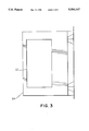
- FIG. 3 is a section taken on the plane 3--3 in FIG. 1;
- FIG. 4 is a perspective view from above of a gutter associated with the invention.
- FIGS. 1-3 A freeze-resistant downspout system embodying the invention is shown in FIGS. 1-3.
- FIGS. 1 and 2 The building shown in FIGS. 1 and 2 has a wall 10 and a roof 12.
- a gutter 14 is attached to the eave 16 of the roof by bolts or screws along its inner edge, and by cantilever brackets 18 at its outer edge, as shown in FIG. 4.
- Water which collects in the gutter escapes through one or more downspouts 20, only one of which is shown in FIGS. 1 and 2.
- the upper end of the downspout terminates in a collector box 22, situated right below an opening 24 in the gutter, and affixed thereto by rivets or the like.
- the collector box 22 is a rectangular parallelipiped, having an open top, a round opening in its bottom, and four vertical walls.
- a short collar 30 is welded or otherwise affixed to the bottom wall, around the opening.
- the downspout has a 45° elbow 26 extending from a hole in the bottom of the collector box, and then a straight segment 28 which leads diagonally through the wall to a further downspout segment, not shown, connected to a storm sewer or the like.
- a further downspout segment not shown, connected to a storm sewer or the like.
- the downspout is supported by a wall jack 32, which is a reinforcing plate having a cross-sectional shape conforming to the wall corrugations.
- the jack Besides supporting the downspout, the jack provides a weather seal where the downspout enters the building.
- the jack-to-wall interface is weather sealed, preferably by applying Butler Manufacturing Company's "Panlastic” tape sealant (a non-hardening butyl-based tape mastic) around the perimeter of the wall jack, between it and the building wall.
- the top of the shroud is covered with a sheet metal closure (not shown) whose main purpose is to keep birds from nesting in the shroud.
- the bottom of the shroud has a vertical flange 38 which is affixed to two wall corrugations. There is a small open space 40 at the bottom, between the corrugations, to permit incidental drainage.
- the shroud is insulated all around with, for example, a one-inch layer 42 of rigid insulation such a "Thermax” board (a rigid polyisocyanate foam board having aluminum foil facings, produced by Celotex Corporation).
- the insulation is bonded to the interior surfaces of the shroud by an adhesive. The insulation helps keep the collector box and elbow above freezing.
- the invention may be applied to an existing building by cutting a slot in the wall panel, for the downspout to pass through.
- a collector box is then installed on the gutter, laterally aligned with the slot.
- a tape sealant is then applied to the wall, around the opening, and a downspout is connected to the gutter box, with the straight segment passing through the slot.
- the wall jack is attached to the wall using blind fasteners such as Butler Manufacturing Company's "Lock-Rivet" fasteners.
- the shroud is secured to the wall, around the collector box, by means of self-drilling screws.
- the downspout conducts heat from within the building toward the gutter. This heating is usually sufficient, with the insulated shroud in place, to keep the portions of the downspout outside the building free of ice, without the use of an auxiliary heater.
- the heat transfer rate may be increased, if desired, by removing some of the wall insulation around the point of wall penetration by the downspout.
Landscapes
- Engineering & Computer Science (AREA)
- Architecture (AREA)
- Civil Engineering (AREA)
- Structural Engineering (AREA)
- Building Environments (AREA)
Abstract
Description
Claims (6)
Priority Applications (2)
| Application Number | Priority Date | Filing Date | Title |
|---|---|---|---|
| US08/540,072 US5584147A (en) | 1995-10-06 | 1995-10-06 | Freeze-resistant downspout system |
| CA002187241A CA2187241A1 (en) | 1995-10-06 | 1996-10-07 | Freeze-resistant downspout system |
Applications Claiming Priority (1)
| Application Number | Priority Date | Filing Date | Title |
|---|---|---|---|
| US08/540,072 US5584147A (en) | 1995-10-06 | 1995-10-06 | Freeze-resistant downspout system |
Publications (1)
| Publication Number | Publication Date |
|---|---|
| US5584147A true US5584147A (en) | 1996-12-17 |
Family
ID=24153870
Family Applications (1)
| Application Number | Title | Priority Date | Filing Date |
|---|---|---|---|
| US08/540,072 Expired - Fee Related US5584147A (en) | 1995-10-06 | 1995-10-06 | Freeze-resistant downspout system |
Country Status (2)
| Country | Link |
|---|---|
| US (1) | US5584147A (en) |
| CA (1) | CA2187241A1 (en) |
Cited By (14)
| Publication number | Priority date | Publication date | Assignee | Title |
|---|---|---|---|---|
| US6105316A (en) * | 1997-02-06 | 2000-08-22 | Cooperatief Advies En Onderzoeksburo U.A. Ecofys | Device for supporting solar panel and a solar panel assembly comprising this device |
| US20040031222A1 (en) * | 2000-12-08 | 2004-02-19 | Ofer Porat | Roofing tiles |
| US20090019792A1 (en) * | 2007-07-19 | 2009-01-22 | Lisa Bukeavich | Bird perching and nesting deterrent |
| US20110303307A1 (en) * | 2009-04-28 | 2011-12-15 | Fiskars Brands, Inc. | Apparatus for diverting rainwater |
| JP2013079537A (en) * | 2011-10-05 | 2013-05-02 | Misawa Homes Co Ltd | Siphon type rain gutter device |
| US8752587B1 (en) * | 2011-01-10 | 2014-06-17 | Dry Basement, Inc. | Apparatus and method for preventing ice blockage of a sump pump discharge line |
| US20190024377A1 (en) * | 2017-07-20 | 2019-01-24 | Preventative Structural Engineering Pty Ltd | Box gutter system and sump overflow device |
| US10428529B1 (en) * | 2017-03-20 | 2019-10-01 | James Tanghongs | Rooftop rainwater drainage assembly |
| US10834915B1 (en) * | 2019-09-05 | 2020-11-17 | Paul Tamulewicz | Avian nesting deterrent |
| US12163335B1 (en) * | 2023-04-21 | 2024-12-10 | John G. Fischer | Drainage junction shield |
| US20250003219A1 (en) * | 2023-07-01 | 2025-01-02 | Gigi Morgan | Integral Roof Drainage System (RainVein) |
| US12320138B1 (en) | 2023-04-21 | 2025-06-03 | John G. Fischer | Mailbox post protector with internal toolless interlock |
| USD1094781S1 (en) | 2024-10-10 | 2025-09-23 | John G. Fischer | Six panel mailbox post protector |
| USD1094782S1 (en) | 2024-10-10 | 2025-09-23 | John G. Fischer | Ten panel mailbox post protector |
Citations (10)
| Publication number | Priority date | Publication date | Assignee | Title |
|---|---|---|---|---|
| US1046910A (en) * | 1911-11-13 | 1912-12-10 | Henry J Wagner | Building construction. |
| US1210502A (en) * | 1914-02-03 | 1917-01-02 | William H Lutton | Greenhouse. |
| US1597104A (en) * | 1924-02-25 | 1926-08-24 | O'donnell John Alvin | Building tile and wall construction |
| US2189466A (en) * | 1939-01-17 | 1940-02-06 | Huth Ludwig | Frostproof jacket |
| US2602764A (en) * | 1949-09-09 | 1952-07-08 | Milton C J Billingham | Insulation for pipes, conduits, and the like |
| US2625263A (en) * | 1950-09-09 | 1953-01-13 | Coleman Co | Pipe and insulation structure |
| US4028895A (en) * | 1975-11-14 | 1977-06-14 | Franzmeier Alvin W | Rain gutter attachment |
| US4142565A (en) * | 1977-06-20 | 1979-03-06 | Plunkett Sr Hermon L | Insulating device for fluid conduit |
| US5010700A (en) * | 1989-06-30 | 1991-04-30 | Earl Blair | Roof jack |
| US5303517A (en) * | 1992-11-10 | 1994-04-19 | Schneider Darwin R | Modular stormwater gutter system |
-
1995
- 1995-10-06 US US08/540,072 patent/US5584147A/en not_active Expired - Fee Related
-
1996
- 1996-10-07 CA CA002187241A patent/CA2187241A1/en not_active Abandoned
Patent Citations (10)
| Publication number | Priority date | Publication date | Assignee | Title |
|---|---|---|---|---|
| US1046910A (en) * | 1911-11-13 | 1912-12-10 | Henry J Wagner | Building construction. |
| US1210502A (en) * | 1914-02-03 | 1917-01-02 | William H Lutton | Greenhouse. |
| US1597104A (en) * | 1924-02-25 | 1926-08-24 | O'donnell John Alvin | Building tile and wall construction |
| US2189466A (en) * | 1939-01-17 | 1940-02-06 | Huth Ludwig | Frostproof jacket |
| US2602764A (en) * | 1949-09-09 | 1952-07-08 | Milton C J Billingham | Insulation for pipes, conduits, and the like |
| US2625263A (en) * | 1950-09-09 | 1953-01-13 | Coleman Co | Pipe and insulation structure |
| US4028895A (en) * | 1975-11-14 | 1977-06-14 | Franzmeier Alvin W | Rain gutter attachment |
| US4142565A (en) * | 1977-06-20 | 1979-03-06 | Plunkett Sr Hermon L | Insulating device for fluid conduit |
| US5010700A (en) * | 1989-06-30 | 1991-04-30 | Earl Blair | Roof jack |
| US5303517A (en) * | 1992-11-10 | 1994-04-19 | Schneider Darwin R | Modular stormwater gutter system |
Cited By (18)
| Publication number | Priority date | Publication date | Assignee | Title |
|---|---|---|---|---|
| US6105316A (en) * | 1997-02-06 | 2000-08-22 | Cooperatief Advies En Onderzoeksburo U.A. Ecofys | Device for supporting solar panel and a solar panel assembly comprising this device |
| US20040031222A1 (en) * | 2000-12-08 | 2004-02-19 | Ofer Porat | Roofing tiles |
| US7062882B2 (en) | 2000-12-08 | 2006-06-20 | Ofer Porat | Roofing tiles |
| US20090019792A1 (en) * | 2007-07-19 | 2009-01-22 | Lisa Bukeavich | Bird perching and nesting deterrent |
| US7581359B2 (en) * | 2007-07-19 | 2009-09-01 | Lisa Bukeavich | Bird perching and nesting deterrent |
| US20110303307A1 (en) * | 2009-04-28 | 2011-12-15 | Fiskars Brands, Inc. | Apparatus for diverting rainwater |
| US8404110B2 (en) * | 2009-04-28 | 2013-03-26 | Fiskars Brands, Inc. | Apparatus for diverting rainwater |
| US8752587B1 (en) * | 2011-01-10 | 2014-06-17 | Dry Basement, Inc. | Apparatus and method for preventing ice blockage of a sump pump discharge line |
| JP2013079537A (en) * | 2011-10-05 | 2013-05-02 | Misawa Homes Co Ltd | Siphon type rain gutter device |
| US10428529B1 (en) * | 2017-03-20 | 2019-10-01 | James Tanghongs | Rooftop rainwater drainage assembly |
| US20190024377A1 (en) * | 2017-07-20 | 2019-01-24 | Preventative Structural Engineering Pty Ltd | Box gutter system and sump overflow device |
| US10753098B2 (en) * | 2017-07-20 | 2020-08-25 | Dam Buster IP Pty Ltd | Box gutter system and sump overflow device |
| US10834915B1 (en) * | 2019-09-05 | 2020-11-17 | Paul Tamulewicz | Avian nesting deterrent |
| US12163335B1 (en) * | 2023-04-21 | 2024-12-10 | John G. Fischer | Drainage junction shield |
| US12320138B1 (en) | 2023-04-21 | 2025-06-03 | John G. Fischer | Mailbox post protector with internal toolless interlock |
| US20250003219A1 (en) * | 2023-07-01 | 2025-01-02 | Gigi Morgan | Integral Roof Drainage System (RainVein) |
| USD1094781S1 (en) | 2024-10-10 | 2025-09-23 | John G. Fischer | Six panel mailbox post protector |
| USD1094782S1 (en) | 2024-10-10 | 2025-09-23 | John G. Fischer | Ten panel mailbox post protector |
Also Published As
| Publication number | Publication date |
|---|---|
| CA2187241A1 (en) | 1997-04-07 |
Similar Documents
| Publication | Publication Date | Title |
|---|---|---|
| US5584147A (en) | Freeze-resistant downspout system | |
| US5391858A (en) | Ice dam melting system | |
| US4288951A (en) | Auxiliary insulated roof system | |
| US3797180A (en) | Ventilated roof construction | |
| US4432341A (en) | Solar heater and roof attachment means | |
| US6694693B2 (en) | Insulation block for roof structure | |
| US4320605A (en) | Insulation panel | |
| AU2017208335B2 (en) | Storage tank insulation joint apparatus and method | |
| US4663909A (en) | Outer heat insulating structure on a building roof | |
| WO2001044598A1 (en) | Roof and roof board material | |
| US20100024324A1 (en) | Roof eaves ice melting system and method of installation | |
| US4084368A (en) | Apparatus for insulating purlins | |
| US20050217196A1 (en) | Apparatus, method and system for sealing and insulating ventilation space | |
| CN101203718A (en) | Solar collectors | |
| JPH0322498B2 (en) | ||
| RU2655261C2 (en) | Method for preventing formation of icicles on the skirting of a pitched roof | |
| JPS634107Y2 (en) | ||
| CN223446482U (en) | Metal exterior wall sandwich panel structure | |
| CN224032028U (en) | Go out roofing steel column node and have its building structure | |
| RU2779365C1 (en) | Roofing with means to prevent the formation of ice and icicles | |
| JP3258917B2 (en) | Eaves structure | |
| JP3204789B2 (en) | Attic ventilation structure | |
| JP3722691B2 (en) | Solar collector installation structure | |
| JPS6120927Y2 (en) | ||
| JPH0439933Y2 (en) |
Legal Events
| Date | Code | Title | Description |
|---|---|---|---|
| AS | Assignment |
Owner name: BUTLER MANUFACTURING COMPANY, INC., MISSOURI Free format text: ASSIGNMENT OF ASSIGNORS INTEREST;ASSIGNORS:AGEE, RALPH K.;JACKSON, MICHAEL E.;REEL/FRAME:007713/0452 Effective date: 19950929 |
|
| AS | Assignment |
Owner name: BUTLER MANUFACTURING COMPANY, MISSOURI Free format text: ASSIGNMENT OF ASSIGNORS INTEREST;ASSIGNORS:AGEE, RALPH K.;JACKSON, MICHAEL E.;REEL/FRAME:008461/0211 Effective date: 19970408 |
|
| FEPP | Fee payment procedure |
Free format text: PAYOR NUMBER ASSIGNED (ORIGINAL EVENT CODE: ASPN); ENTITY STATUS OF PATENT OWNER: LARGE ENTITY |
|
| FPAY | Fee payment |
Year of fee payment: 4 |
|
| SULP | Surcharge for late payment | ||
| REMI | Maintenance fee reminder mailed | ||
| LAPS | Lapse for failure to pay maintenance fees | ||
| STCH | Information on status: patent discontinuation |
Free format text: PATENT EXPIRED DUE TO NONPAYMENT OF MAINTENANCE FEES UNDER 37 CFR 1.362 |
|
| FP | Lapsed due to failure to pay maintenance fee |
Effective date: 20041217 |