US5579960A - Air powered dispensing pen for viscous fluids - Google Patents

Air powered dispensing pen for viscous fluids Download PDF

Info

Publication number
US5579960A
US5579960A US08/582,226 US58222696A US5579960A US 5579960 A US5579960 A US 5579960A US 58222696 A US58222696 A US 58222696A US 5579960 A US5579960 A US 5579960A
Authority
US
United States
Prior art keywords
pen
venturi
barrel member
tubular barrel
viscous fluid
Prior art date
Legal status (The legal status is an assumption and is not a legal conclusion. Google has not performed a legal analysis and makes no representation as to the accuracy of the status listed.)
Expired - Lifetime
Application number
US08/582,226
Inventor
Richard R. Scott
Current Assignee (The listed assignees may be inaccurate. Google has not performed a legal analysis and makes no representation or warranty as to the accuracy of the list.)
SILKPAINT Corp
Original Assignee
Scott; Richard R.
Priority date (The priority date is an assumption and is not a legal conclusion. Google has not performed a legal analysis and makes no representation as to the accuracy of the date listed.)
Filing date
Publication date
Application filed by Scott; Richard R. filed Critical Scott; Richard R.
Priority to US08/582,226 priority Critical patent/US5579960A/en
Application granted granted Critical
Publication of US5579960A publication Critical patent/US5579960A/en
Assigned to OTTO, KARL J. reassignment OTTO, KARL J. ASSIGNMENT OF ASSIGNORS INTEREST (SEE DOCUMENT FOR DETAILS). Assignors: SCOTT, RICHARD R.
Assigned to SILKPAINT CORPORATION reassignment SILKPAINT CORPORATION ASSIGNMENT OF ASSIGNORS INTEREST (SEE DOCUMENT FOR DETAILS). Assignors: OTTO, KARL J.
Anticipated expiration legal-status Critical
Expired - Lifetime legal-status Critical Current

Links

Images

Classifications

    • BPERFORMING OPERATIONS; TRANSPORTING
    • B05SPRAYING OR ATOMISING IN GENERAL; APPLYING FLUENT MATERIALS TO SURFACES, IN GENERAL
    • B05BSPRAYING APPARATUS; ATOMISING APPARATUS; NOZZLES
    • B05B11/00Single-unit hand-held apparatus in which flow of contents is produced by the muscular force of the operator at the moment of use
    • B05B11/0005Components or details
    • B05B11/0035Pen-like sprayers
    • BPERFORMING OPERATIONS; TRANSPORTING
    • B05SPRAYING OR ATOMISING IN GENERAL; APPLYING FLUENT MATERIALS TO SURFACES, IN GENERAL
    • B05CAPPARATUS FOR APPLYING FLUENT MATERIALS TO SURFACES, IN GENERAL
    • B05C17/00Hand tools or apparatus using hand held tools, for applying liquids or other fluent materials to, for spreading applied liquids or other fluent materials on, or for partially removing applied liquids or other fluent materials from, surfaces
    • B05C17/005Hand tools or apparatus using hand held tools, for applying liquids or other fluent materials to, for spreading applied liquids or other fluent materials on, or for partially removing applied liquids or other fluent materials from, surfaces for discharging material from a reservoir or container located in or on the hand tool through an outlet orifice by pressure without using surface contacting members like pads or brushes
    • B05C17/00523Hand tools or apparatus using hand held tools, for applying liquids or other fluent materials to, for spreading applied liquids or other fluent materials on, or for partially removing applied liquids or other fluent materials from, surfaces for discharging material from a reservoir or container located in or on the hand tool through an outlet orifice by pressure without using surface contacting members like pads or brushes provided with means to heat the material
    • B05C17/0054Hand tools or apparatus using hand held tools, for applying liquids or other fluent materials to, for spreading applied liquids or other fluent materials on, or for partially removing applied liquids or other fluent materials from, surfaces for discharging material from a reservoir or container located in or on the hand tool through an outlet orifice by pressure without using surface contacting members like pads or brushes provided with means to heat the material the driving means for the material being pneumatic or hydraulic

Abstract

A pneumatic dispenser for viscous fluids including a tubular pen barrel, a dispensing nozzle on one end of the pen barrel, and a pen cap constructed to sealingly receive the pen barrel. The pen cap also includes an air line connection and venturi arrangement so that when supplied with compressed air, air flow through the venturi reduces pressure in the pen and holds fluid in the pen. Interrupting air flow through the venturi causes pressure to increase in pen and fluid to be extruded through pen nozzle.

Description

This application is a continuation of Ser. No. 08/236960 filed May 2, 1994, now abandoned.
BACKGROUND
1. Field of Invention
This invention relates to dispensers for viscous fluids and more particularly to a dispensing pen which is operative for effectively and accurately dispensing controlled amounts of a viscous fluid.
2. Description of Prior Art
Currently, the most common type of dispenser for viscous fluids is the plastic squeeze bottle. While they are economical to produce, they are limited in the length of continuous line they can extrude before they must be allowed to return to their original shape. This introduces air bubbles into the fluid which can be extruded in subsequent use. Start and stop blobs and occasional bubbles are common problems. Also, many people with arthritis, carpal tunnel syndrome, or other wrist or hand problems find it difficult and tiresome to exert the constant pressure necessary to extrude a nice even line.
Also on the market are miniature caulk guns. These use medical type syringes for barrels and a ratchet trigger assembly to advance a piston for extruding a fluid. From the hand's position on the trigger these devices lack precise control over the tip. Like the squeeze bottle they are limited in the length of continuous line they can produce. Also, constant pressure must be maintained to produce an even line and hand fatigue is again a problem.
Another approach, used mainly in industry, is a dispensing pen that has a separate reservoir containing the fluid which is pressurized with air. The fluid is forced through a tube to a hand-held instrument containing a control valve. While working effectively, this dispenser requires a regulated air supply and is difficult to clean between fluid changes. To accomplish cleaning, the valve body must be disassembled and the reservoir and supply tube must be emptied and flushed.
A fourth, and the most expensive approach, is another air powered device. Basically, this is a syringe for holding the fluid fitted with a cap and an air line. This air line is connected to a control box hooked to a regulated air supply. The control box contains a venturi apparatus, so by means of a foot switch the operator can pressurize the syringe and extrude fluid through the tip, or release the switch and create a partial vacuum in the syringe and stop all flow of material. These units work well, but are expensive by themselves, and in addition require a regulated air supply. This amount of equipment can be cumbersome as well if weight or space is a consideration.
OBJECTS AND ADVANTAGES
Accordingly, several objects and advantages of my dispenser are its ability to produce long, continuous lines, without start and stop blobs or bubbles, and without having to squeeze a bottle or trigger. My dispenser has further been designed to allow fingertip control of both the movement of the pen and the flow of fluid. The pen barrel and nozzle are the only elements that come in contact with the fluid and they are readily changeable and easy to clean. My dispenser also limits post extrusion using a partial vacuum as in the most expensive industrial dispensers. However, my dispenser accomplishes this by a venturi incorporated in the pen cap and controlled by fingertip. Also, where other dispensers require a regulated air supply, my dispenser operates with a conventional, inexpensive aquarium pump.
Thus, my dispenser produces lines that are far superior to squeeze bottles and caulking gun type dispensers. And, being air powered, it causes little or no hand fatigue. Compared to other pneumatic dispensers, my dispenser is lighter, more compact, simpler to operate, easier to clean, and much more economical. And it produces lines comparable to any dispenser available. Further objects and advantages will become apparent from a consideration of the drawings and ensuing description.
DRAWING FIGURES
In the drawings, closely related figures have the same number, but different alphabetical suffixes.
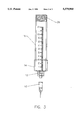
FIG. 1 is a perspective view of the dispensing pen.
FIG. 2A is a top view of the pen cap.
FIG. 2B is a side view cross-section of the pen cap.
FIG. 3 is a side view of the pen barrel and nozzle.
DESCRIPTION FIGS. 1-3
FIG. 1 shows a perspective view of my dispensing pen 18. A nozzle 10 is a disposable hypodermic needle where the stainless steel canula tubing has been square cut leaving 1 c.m. of the tubing and the remaining end deburred and chamfered. A luer lock connector 12 connects nozzle 10 to a 12 c.c. syringe or a pen barrel 16. Pen barrel 16 has been machined with a male thread 26--1.9 c.m. dia., 6.3 threads/c.m. (3/4"NF16). A pen cap 28 has been machined with a female thread 30--1.9 c.m. dia., 6.3 threads/c.m. (3/4"NF16). Male thread 26 and female thread 30 allow connection of pen barrel 16 and pen cap 28. A vinyl seal 14 is a 2 c.m. long section of vinyl tubing, 1.9 c.m. O.D., 1.6 c.m. I.D. Vinyl seal 14 is situated around bottom end of pen barrel 16 to effect an airtight seal with pen cap 28.
FIG. 2-B shows an air line connector 20 which is a 1.6 c.m. long brass tube 0.16 c.m. O.D., 0.08 c.m. I.D. This air line connector 20 is reduced on one end to 0.05 c.m. I.D. by an orifice 36. Air line connector 20 is glued into one end of a control tube 22 with the addition of a vinyl bushing 34. Control tube 22 is a 9.4 c.m. long polystyrene tube, 0.64 c.m. O.D., 0.32 c.m. I.D. Vinyl bushing 34 is a 0.64 c.m. long vinyl tube, 0.32 c.m. O.D., 0.16 c.m. I.D. A pressure transfer hole 38, 0.16 c.m. diameter is located in control tube 22 with its edge adjacent to orifice 36. Adjacent to opposite edge of pressure transfer hole 38 is a movable venturi element 40. Movable venturi element 40 is a 0.8 c.m. long vinyl tube 0.32 c.m. O.D., 0.16 c.m. I.D. A vein 23, 0.64 c.m. radius, is routed. 0.12 c.m. deep, longitudinally, the entire length of pen cap 28. This is best shown in FIG. 2A. Pen cap 28 is constructed of a 10 c.m. section of PVC tube; 21 m.m. O.D., 18 m.m. I.D. (1/2" SDR 13.5 PVC pipe).
FIG. 2B shows a hole 39, 0.16 c.m. diameter, drilled in the center of vein 23 at a distance from the end so that when hole 38 and hole 39 are lined up, a flow control port 24 will be flush with bottom edge of pen cap 28. Control tube 22 is glued in this position with special attention to forming an airtight seal around hole 38 and hole 39. Control tube 22 has been reamed to 0.48 c.m. I.D. and cut at a 22 degree angle to form control port 24. A pen cap end plug 32 is glued in threaded end of pen cap 28. All glue used is waterproof epoxy. The open end of pen cap 28 has been drilled to a diameter to slidably receive pen barrel 16 shown in FIG. 3.
Operation FIGS. 1-3
The manner of operation of dispensing pen 18 is to connect a 0.32 c.m. O.D., 0.16 c.m. I.D. vinyl tubing (not shown) from air connector 20 to a conventional aquarium pump (not shown), supplying air at a rate of 3-4 liters per minute at a pressure of 0.18 KG-0.3 KG per cm2. Next, remove pen barrel 16 and fill with up to 12 c.c. of desired fluid (glue, paint, fabric paint, dye resist, etc.). Reinsert pen barrel 16 into pen cap 28 and screw until vinyl seal 14 seats against pen cap 28 forming an airtight seal. Dispensing pen 18 should be held with point down when loaded to keep fluid in pen barrel 16. Air flow through orifice 36 and movable venturi element 40 will create a partial vacuum in pen cap 28 and prevent extrusion of fluid through nozzle 10. Movable venturi element 40 is slidable in control tube 22 for adjusting vacuum to accommodate variations in aquarium pump outputs. Pen should be held so forefinger rests near flow control port 24. This port has been reamed and cut on an angle to facilitate its use. Covering port 24 will cause pressure to rise in pen cap 28 via pressure transfer hole 38 and pressure transfer hole 39 and fluid will be extruded through nozzle 10. Uncovering flow control port 24 will stop flow of fluid. Pen barrel 16 and nozzle 10 are easily cleaned with a 12 c.c. syringe plunger (not shown).
Thus the reader will see that the dispensing pen 18 of the invention provides a simple, reliable, and economical device that can be used by almost anyone. While my above description contains many specificities, these should not be construed as limitations on the scope of the invention, but rather as an exemplification of one preferred embodiment thereof. Many other variations are possible. For example, pen cap 28 and control tube 22 could be molded as one piece. Control tube 22 could even be contained entirely in the side wall of pen cap 28.
Accordingly, the scope of the invention should be determined not by the embodiment illustrated, but by the appended claims and their legal equivalents.

Claims (2)

I claim:
1. A dispenser for a viscous fluid comprising:
a) a tubular barrel member having a chamber therein containing said viscous fluid, said tubular barrel member having a first end and a second end, opposite of each other;
b) a nozzle means defining a dispensing nozzle having a reduced dispensing aperture therein, said nozzle means communicating with said first end of said tubular barrel member for receiving said viscous fluid through said reduced dispensing aperture when pressure is applied to said viscous fluid; and
c) a pen cap element which sealably receives said second end of said tubular barrel member and includes: a venturi located adjacent to a pressure transfer hole and a valve means for controlling air flow from a compressed air source so that when said valve means is open, air flows through said venturi and a partial vacuum is created in said tubular barrel member via said pressure transfer hole, and when said valve means is closed pressure increases in said tubular barrel member through said pressure transfer hole and said viscous fluid is extruded through said nozzle means.
2. The dispensing pen of claim 1 wherein said venturi consists of an orifice and a movable venturi element that enable vacuum to be adjusted.
US08/582,226 1994-05-02 1996-01-03 Air powered dispensing pen for viscous fluids Expired - Lifetime US5579960A (en)

Priority Applications (1)

Application Number Priority Date Filing Date Title
US08/582,226 US5579960A (en) 1994-05-02 1996-01-03 Air powered dispensing pen for viscous fluids

Applications Claiming Priority (2)

Application Number Priority Date Filing Date Title
US23696094A 1994-05-02 1994-05-02
US08/582,226 US5579960A (en) 1994-05-02 1996-01-03 Air powered dispensing pen for viscous fluids

Related Parent Applications (1)

Application Number Title Priority Date Filing Date
US23696094A Continuation 1994-05-02 1994-05-02

Publications (1)

Publication Number Publication Date
US5579960A true US5579960A (en) 1996-12-03

Family

ID=22891740

Family Applications (1)

Application Number Title Priority Date Filing Date
US08/582,226 Expired - Lifetime US5579960A (en) 1994-05-02 1996-01-03 Air powered dispensing pen for viscous fluids

Country Status (1)

Country Link
US (1) US5579960A (en)

Cited By (5)

* Cited by examiner, † Cited by third party
Publication number Priority date Publication date Assignee Title
US6039223A (en) * 1998-10-23 2000-03-21 Damask; John E. Bulk load dispenser and method
US20040161510A1 (en) * 2003-02-14 2004-08-19 Michele Hester Confectionery composition and methods of using the same for decorating
US6926177B1 (en) 2000-03-31 2005-08-09 William M. Scott Device for dispensing substance from a cartridge
US20080041880A1 (en) * 2006-06-05 2008-02-21 Roger Babineau Handheld foodstuff dispenser
WO2010124994A3 (en) * 2009-04-28 2011-03-31 L'oreal Coloured composition

Citations (6)

* Cited by examiner, † Cited by third party
Publication number Priority date Publication date Assignee Title
US1782681A (en) * 1927-01-12 1930-11-25 Leonard R Foss Feed gun
US3258176A (en) * 1964-09-24 1966-06-28 Zenith Radio Corp Pneumatic glue dispenser
US3871553A (en) * 1973-03-15 1975-03-18 Owatonna Tool Co Dispensing gun for semi-liquid material
US3921858A (en) * 1973-11-05 1975-11-25 Robert A Bemm Automatic confection decorating system
US4678107A (en) * 1985-08-02 1987-07-07 Mark L. Anderson Dripless dispenser for liquids and viscous fluids
US5022563A (en) * 1990-01-10 1991-06-11 Electron Fusion Devices, Inc. Dispenser-gun assembly for viscous fluids and dispenser therefor

Patent Citations (6)

* Cited by examiner, † Cited by third party
Publication number Priority date Publication date Assignee Title
US1782681A (en) * 1927-01-12 1930-11-25 Leonard R Foss Feed gun
US3258176A (en) * 1964-09-24 1966-06-28 Zenith Radio Corp Pneumatic glue dispenser
US3871553A (en) * 1973-03-15 1975-03-18 Owatonna Tool Co Dispensing gun for semi-liquid material
US3921858A (en) * 1973-11-05 1975-11-25 Robert A Bemm Automatic confection decorating system
US4678107A (en) * 1985-08-02 1987-07-07 Mark L. Anderson Dripless dispenser for liquids and viscous fluids
US5022563A (en) * 1990-01-10 1991-06-11 Electron Fusion Devices, Inc. Dispenser-gun assembly for viscous fluids and dispenser therefor

Non-Patent Citations (10)

* Cited by examiner, † Cited by third party
Title
Composite Applicator article from "The Engravers Journal" Nov./Dec. 1979.
Composite Applicator article from The Engravers Journal Nov./Dec. 1979. *
Courtaulde Aerospace/ Semco catalogue *
EFD Catalogue 92/93. *
Glenmark brochure. *
I & J Fisnar catalogue. *
Philip Fishman Bulletin 104. *
Techon Systems brochure. *
Techon Systems catalogue. *
Tridak catalogue. *

Cited By (8)

* Cited by examiner, † Cited by third party
Publication number Priority date Publication date Assignee Title
US6039223A (en) * 1998-10-23 2000-03-21 Damask; John E. Bulk load dispenser and method
US6926177B1 (en) 2000-03-31 2005-08-09 William M. Scott Device for dispensing substance from a cartridge
US20040161510A1 (en) * 2003-02-14 2004-08-19 Michele Hester Confectionery composition and methods of using the same for decorating
US7108880B2 (en) 2003-02-14 2006-09-19 Waldron Llc Confectionery composition and methods of using the same for decorating
US20060292290A1 (en) * 2003-02-14 2006-12-28 Michele Hester Confectionery composition and methods of using the same for decorating
US7651709B2 (en) 2003-02-14 2010-01-26 Waldron Llc Confectionery composition for decorating
US20080041880A1 (en) * 2006-06-05 2008-02-21 Roger Babineau Handheld foodstuff dispenser
WO2010124994A3 (en) * 2009-04-28 2011-03-31 L'oreal Coloured composition

Similar Documents

Publication Publication Date Title
AU602017B2 (en) Back-fill syringe
US6425885B1 (en) Hydraulic syringe
EP1015382B1 (en) Fluid dispenser apparatus
CA2199795C (en) Fluid delivery apparatus
US6902339B2 (en) Fluid dispenser
US6364170B1 (en) Fluid dispenser apparatus
WO2004060259A3 (en) Hand held oral irrigator
AU672424B2 (en) Improvements in or relating to gas powered applicators
US4507004A (en) Side handle reservoir brush
NO980298D0 (en) Multicomponent applicator for liquid mixtures
US5579960A (en) Air powered dispensing pen for viscous fluids
FR2848859B1 (en) DISPENSING DEVICE FOR A NETWORK FOR DELIVERING MEDICAL FLUIDS TO A PATIENT
US3217932A (en) Dispenser for liquid and semiliquid materials
ATE94042T1 (en) DEVICE FOR DELIVERING FLOWABLE MEDIA.
US6334774B1 (en) Flow through applicator with resilient tip
US5358150A (en) Pressurized fluid dispensing device
GB1113152A (en) Improvements relating to fluid hose attachments
US3482739A (en) Fluid dispenser
US3277894A (en) Syringe package having parts of different hardness
US10632483B1 (en) Universal pressurized spray adapter
US20040200861A1 (en) Plunger damping means
DE20011292U1 (en) Dispensing pump
US3593962A (en) Valve-controlled rotary nozzle
CA1289836C (en) Back-fill syringe
DE10322259B3 (en) Liquid dispenser has connection ejection line connected to dosing device at highest point of dosing device, cylinder wall accommodated in gap between actuating sleeve and piston surface

Legal Events

Date Code Title Description
STCF Information on status: patent grant

Free format text: PATENTED CASE

FPAY Fee payment

Year of fee payment: 4

REMI Maintenance fee reminder mailed
FPAY Fee payment

Year of fee payment: 8

SULP Surcharge for late payment

Year of fee payment: 7

AS Assignment

Owner name: OTTO, KARL J., MISSOURI

Free format text: ASSIGNMENT OF ASSIGNORS INTEREST;ASSIGNOR:SCOTT, RICHARD R.;REEL/FRAME:016323/0250

Effective date: 20041103

AS Assignment

Owner name: SILKPAINT CORPORATION, MISSOURI

Free format text: ASSIGNMENT OF ASSIGNORS INTEREST;ASSIGNOR:OTTO, KARL J.;REEL/FRAME:016835/0854

Effective date: 20050920

FPAY Fee payment

Year of fee payment: 12