US5577145A - Optical connector including split sleeve secured in expanded state - Google Patents
Optical connector including split sleeve secured in expanded state Download PDFInfo
- Publication number
- US5577145A US5577145A US08/428,230 US42823095A US5577145A US 5577145 A US5577145 A US 5577145A US 42823095 A US42823095 A US 42823095A US 5577145 A US5577145 A US 5577145A
- Authority
- US
- United States
- Prior art keywords
- optical
- split sleeve
- optical connector
- optical medium
- sleeve
- Prior art date
- Legal status (The legal status is an assumption and is not a legal conclusion. Google has not performed a legal analysis and makes no representation as to the accuracy of the status listed.)
- Expired - Lifetime
Links
- 230000003287 optical effect Effects 0.000 title claims abstract description 105
- 230000005489 elastic deformation Effects 0.000 claims abstract description 14
- 238000006243 chemical reaction Methods 0.000 claims description 16
- 230000005693 optoelectronics Effects 0.000 claims description 15
- 230000005540 biological transmission Effects 0.000 claims description 8
- 238000003780 insertion Methods 0.000 claims description 3
- 230000037431 insertion Effects 0.000 claims description 3
- 230000006835 compression Effects 0.000 claims 1
- 238000007906 compression Methods 0.000 claims 1
- 238000004519 manufacturing process Methods 0.000 description 10
- 239000013307 optical fiber Substances 0.000 description 5
- 238000000034 method Methods 0.000 description 4
- 230000013011 mating Effects 0.000 description 3
- 238000003466 welding Methods 0.000 description 3
- 238000010276 construction Methods 0.000 description 2
- 239000000835 fiber Substances 0.000 description 2
- 239000000463 material Substances 0.000 description 2
- 239000002184 metal Substances 0.000 description 2
- 239000004033 plastic Substances 0.000 description 2
- 229920003023 plastic Polymers 0.000 description 2
- 238000005452 bending Methods 0.000 description 1
- 230000007423 decrease Effects 0.000 description 1
- 230000003247 decreasing effect Effects 0.000 description 1
- 239000000428 dust Substances 0.000 description 1
- 230000005611 electricity Effects 0.000 description 1
- 230000002035 prolonged effect Effects 0.000 description 1
- 239000004065 semiconductor Substances 0.000 description 1
- 229910001220 stainless steel Inorganic materials 0.000 description 1
- 239000010935 stainless steel Substances 0.000 description 1
- 229920003002 synthetic resin Polymers 0.000 description 1
- 239000000057 synthetic resin Substances 0.000 description 1
Images


Classifications
-
- G—PHYSICS
- G02—OPTICS
- G02B—OPTICAL ELEMENTS, SYSTEMS OR APPARATUS
- G02B6/00—Light guides; Structural details of arrangements comprising light guides and other optical elements, e.g. couplings
- G02B6/24—Coupling light guides
- G02B6/36—Mechanical coupling means
- G02B6/38—Mechanical coupling means having fibre to fibre mating means
- G02B6/3807—Dismountable connectors, i.e. comprising plugs
- G02B6/3873—Connectors using guide surfaces for aligning ferrule ends, e.g. tubes, sleeves, V-grooves, rods, pins, balls
- G02B6/3874—Connectors using guide surfaces for aligning ferrule ends, e.g. tubes, sleeves, V-grooves, rods, pins, balls using tubes, sleeves to align ferrules
- G02B6/3877—Split sleeves
-
- G—PHYSICS
- G02—OPTICS
- G02B—OPTICAL ELEMENTS, SYSTEMS OR APPARATUS
- G02B6/00—Light guides; Structural details of arrangements comprising light guides and other optical elements, e.g. couplings
- G02B6/24—Coupling light guides
- G02B6/42—Coupling light guides with opto-electronic elements
- G02B6/4292—Coupling light guides with opto-electronic elements the light guide being disconnectable from the opto-electronic element, e.g. mutually self aligning arrangements
-
- G—PHYSICS
- G02—OPTICS
- G02B—OPTICAL ELEMENTS, SYSTEMS OR APPARATUS
- G02B6/00—Light guides; Structural details of arrangements comprising light guides and other optical elements, e.g. couplings
- G02B6/24—Coupling light guides
- G02B6/36—Mechanical coupling means
- G02B6/38—Mechanical coupling means having fibre to fibre mating means
- G02B6/3807—Dismountable connectors, i.e. comprising plugs
- G02B6/3833—Details of mounting fibres in ferrules; Assembly methods; Manufacture
- G02B6/3847—Details of mounting fibres in ferrules; Assembly methods; Manufacture with means preventing fibre end damage, e.g. recessed fibre surfaces
- G02B6/3849—Details of mounting fibres in ferrules; Assembly methods; Manufacture with means preventing fibre end damage, e.g. recessed fibre surfaces using mechanical protective elements, e.g. caps, hoods, sealing membranes
-
- G—PHYSICS
- G02—OPTICS
- G02B—OPTICAL ELEMENTS, SYSTEMS OR APPARATUS
- G02B6/00—Light guides; Structural details of arrangements comprising light guides and other optical elements, e.g. couplings
- G02B6/24—Coupling light guides
- G02B6/36—Mechanical coupling means
- G02B6/38—Mechanical coupling means having fibre to fibre mating means
- G02B6/3807—Dismountable connectors, i.e. comprising plugs
- G02B6/3833—Details of mounting fibres in ferrules; Assembly methods; Manufacture
- G02B6/3851—Ferrules having keying or coding means
-
- G—PHYSICS
- G02—OPTICS
- G02B—OPTICAL ELEMENTS, SYSTEMS OR APPARATUS
- G02B6/00—Light guides; Structural details of arrangements comprising light guides and other optical elements, e.g. couplings
- G02B6/24—Coupling light guides
- G02B6/36—Mechanical coupling means
- G02B6/38—Mechanical coupling means having fibre to fibre mating means
- G02B6/3807—Dismountable connectors, i.e. comprising plugs
- G02B6/389—Dismountable connectors, i.e. comprising plugs characterised by the method of fastening connecting plugs and sockets, e.g. screw- or nut-lock, snap-in, bayonet type
- G02B6/3893—Push-pull type, e.g. snap-in, push-on
Definitions
- the present invention relates to an optical connector for optical connection between optical transmission lines or between an optical transmission line and a opto-electronic conversion element.
- a receptacle housing which, in order to achieve an accurate alignment between a fibre optic ferrule and a opto-electronic conversion element (light emitting element or light receiving element), contains a precision bore to maintain the ferrule accurately in position.
- a precision machine tool In order to achieve the necessary strict tolerances of the fixed bore, it is necessary that the fixed bore of the housing be exactly machined by a precision machine tool. Even if the fixed bore is accurately formed, it does not allow for elastic deformation to accommodate variations in ferrule sizes and manufacturing tolerances associated with the manufacture of the ferrule. It is, therefore, difficult to obtain a standardised optical connector with high reliability of alignment between the ferrule and aforementioned element.
- the required accuracy and stability of alignment requires a relatively long connection between the ferrule and the opto-electronic element, and the fixed bore is formed as a cylindrical projection extending from the receptacle housing, relatively high manufacturing costs are associated with such an the optical connector.
- a precision split sleeve or a hollow tube is employed to connect together two ferrules or to make a connection between one ferrule and an active device on which a dummy ferrule of the same structure as the ferrule is mounted.
- the split sleeve has an inner diameter made slightly smaller than the outer diameter of the ferrules. Since such a split sleeve is always used in a manner which causes the sleeve to expand when fitted onto the ferrules, the diameter of the split sleeve does not have a set, fixed diameter. Because of this, an accurate ferrule-to-ferrule alignment with an adequate pressure force is difficult to achieve.
- the dummy ferrule When the ferrule is connected to the active device, the dummy ferrule is mounted on the forward end portion of the receptacle housing and then needs to be inserted into the split sleeve.
- an even greater ferrule-to-device connection length is required than in the case of the first mentioned connector type, and the optical connector involves a relatively high manufacturing cost.
- the present invention aims to provide an improved optical connector which addresses problems inherent in existing optical connectors.
- the object of the present invention is to provide an optical connector which can accommodate some size variations and manufacturing tolerances, that can be provided as a standardised optical connector with highly reliable connection.
- an optical connector for optically connecting together first and second optical media having corresponding optical input/output ends, comprising: plug means for supporting the first optical medium; receptacle means connectable to the plug means and supporting the second optical medium; and a split tube member having a free end via which the optical input/output end of the first optical medium can be inserted and an end fixed to the receptacle means and located at the optical input/output end of the second optical medium and a slit extending from its free end to its fixed end and gripping the first optical medium through an elastic deformation toward its substantial centre axis, wherein, when the plug mean is connected to the receptacle means, the optical input/output end of the first optical medium is optically aligned with that of .the second optical medium through the elastic deformation of the split tube member.
- the optical connector further comprises urging means for urging the gripping of the first optical medium through the elastic deformation of the split tube member.
- the optical connector includes the urging means comprised of guide means for guiding the insertion of the first optical medium into the split tube member.
- the first optical medium includes an optical transmission line and the second optical medium includes an optical transmission line or a opto-electronic conversion element.
- the first optical medium is gripped through the elastic deformation of the split type tube member and the fixed end of the split tube member is fixed to the receptacle means, thus suppressing a loss in the elastic deformation characteristic of the split tube member with a passage of time in use.
- FIG. 1 is a perspective, exploded view showing an optical connector according to a fast embodiment of the present invention
- FIG. 2 is a perspective view showing a receptacle in an assembled optical connector in FIG. 1;
- FIG. 3(A) is a perspective view showing an active device associated with the receptacle
- FIG. 3(B) is a perspective view showing another active device
- FIG. 4 is a perspective, enlarged view showing first and second sleeves of the optical connector shown in FIG. 1;
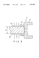
- FIG. 5 is a cross-sectional view showing a first split sleeve in a normal state
- FIG. 6 is a cross-sectional view showing the first split sleeve into which a diameter adjusting plug is inserted
- FIG. 7 is a cross-sectional view showing the first split sleeve fixed to the receptacle with the diameter adjusting plug inserted into the sleeve;
- FIG. 8 is a cross-sectional view showing a receptacle and the first split sleeve fitted into the receptacle with the diameter adjusting plug removed;
- FIG. 9 is a cross-sectional view showing the receptacle and the first split sleeve fitted into the receptacle with a ferrule inserted into the first split sleeve;
- FIG. 10(A) is a perspective, enlarged view showing a frame for fixing the receptacle in place and,
- FIG. 10(B) is a perspective view showing the frame of FIG. 10(A) in an assembled state
- FIG. 11 is a perspective view showing still another frame
- FIG. 12 is a perspective view showing still yet another frame.
- FIG. 13 is a cross-sectional view showing a receptacle on which a housing is mounted with a light/electricity conversion circuit incorporated therein.
- an optical connector includes a plug 1, a receptacle 2 associated with the plug 1, and a first sleeve 13a arranged between the plug 1 and the receptacle 2.
- the receptacle 2 includes a rectangular housing 3 having a rectangular opening 4 at one end and an active device 5 enclosed in the housing 3.
- the rectangular housing 3 be of the so-called SC style shell construction as shown in FIG. 2.
- the rectangular housing 3 is comprised of a combination of two shells 3a, 3b of injection-molded synthetic resin.
- Each of the shells 3a and 3b is of such a type as to hold the rear end portion of the active device 5 therebetween. More particularly, the shells 3a and 3b provide a pair of recesses 6a, 6b at those inner walls of their rear end portions which face each other when the shells 3a and 3b are assembled together. Grooves 7 are provided in the inner walls of the recesses 6a, 6b of the shells to allow a flange 8 which is provided on the outer periphery of the active device 5 to be fired in the grooves 7.
- a projection 9 and hole 10 are formed at each of the mating end face portions of the rear end portions of the shells 3a and 3b.
- Cutouts 11a and 11b are provided on the forward end side of the mating end faces of the shells 3a and 3b.
- the cutouts 11a and 11b provide a key-way 11 when these shells 3a and 3b are assembled together.
- a key 12 is provided at the outer periphery of a housing of the plug 1 and adapted to be inserted into the key-way 11.
- the plug 1 is oriented so that an optical fibre ferrule 18 can be inserted into the first sleeve 13a.
- the active device 5 includes a front housing 15 having a flange 8 and cylindrical tube 14 extending, as an integral unit, in the axial direction of the first sleeve 13a and made of a metal, such as stainless steel, or plastics, and a rear housing 16 having, at the first sleeve 13a side, an optical input/output window, not shown, for a opto-electronic conversion element as will be set out below.
- the known opto-electronic conversion element (light emitting element or light receiving element) is incorporated into the rear housing 16.
- the conversion element has leads 17 projecting from the rear wall of the rear housing 16, as shown in FIG. 3(A).
- the light emitting/receiving surface of the conversion element corresponds to the optical input/output end.
- the rear housing 16 may be made integral with the front housing 15 as shown in FIG. 3(B ).
- the first sleeve 13a is of such a split type that it has a slit, along its length, extending from its free end (plug 1 side) to its fixed end (receptacle 2 side).
- the split sleeve 13a is made of plastics or other suitable materials having a proper elastic deformation characteristic.
- the fixed end of the split sleeve 13a is inserted into the cylindrical tube 14 and fixed there.
- the flange 8 is omitted for clarity of the split sleeve 13a.
- a split sleeve 13a has an inner diameter d1 made slightly smaller than the diameter of the ferrule 18 (FIG. 5).
- a diameter adjusting plug 18' whose outer diameter is equal to a maximum tolerance outer diameter d2 for the normal use of the ferrule 18 is inserted into the sleeve 13a to make the inner diameter of the sleeve 13a equal to the diameter d2 of the diameter adjusting plug 18' (FIG. 6).
- the fixing end of the sleeve 13a is fixed, or normally bonded, to the cylindrical tube 14 (FIG.
- the deformation of the sleeve 13a causes the inner diameter of the sleeve 13a to be further decreased so that the split sleeve 13a can be returned back to its original inner diameter d1 in which case the inner diameter of the split sleeve 13a is made positively smaller than the inner diameter d2 value assumed when the ferrule 18 has been inserted into the split sleeve 13a (FIG. 8). That is, the inner diameter of the sleeve 13a may be varied along the length of the sleeve 13a due to the deformation of the sleeve 13a.
- any ferrule falling in a normal tolerance range is very intimately gripped due to the resultant deformation of the sleeve 13a (FIG. 9).
- the ferrule 18 is inserted into the free end portion of the first sleeve 13a, it is possible to achieve a stabler connection characteristic with a low connection loss. It is thus possible to achieve accurate alignment of the ferrule 18 relative to the optical input/output window and hence the opto-electronic element.
- the active device 5 further have a second sleeve 13b into which the free end portion of the first sleeve 13a is inserted.
- the second sleeve 13b is comprised of a split sleeve having a slit, along its length, extending from one end (plug 1 side) to the other end (receptacle 2 side).
- the second sleeve 13b will typically be made of the same material as that of the first sleeve 13a.
- the ferrule 18 which, is inserted into the second sleeve 13b from the side which will form its free end and is guided past the other end of the second sleeve 13b to the fixed end of the first sleeve 13a.
- the second sleeve 13b which is then pushed over the free end of the sleeve 13a further decreases the inner diameter of the free end portion of the first sleeve 13a, thereby increasing a gripping force on the ferrule 18 thus inserted into the first sleeve 13a.
- the second sleeve 13b may be properly so designed as to be formed as an non-split type, etc., having internal ribs so that it can be properly fitted over the fixed end portion of the first sleeve 13a.
- the free end of the second sleeve 13b is designed as a re-entrant cone so as to readily guide the ferrule's forward end into the first sleeve 13a.
- the flange 8 of the active device 5 includes a retaining section 8a fined into the groove 7 of the recess 7 and a rotation-stop flat (or detent) section 8b situated at an angle of substantially 90 ⁇ relative to the retaining section 8a and hence the axis of the first sleeve 13a and provided as a partial cutout section.
- the flange 8 is fitted into the groove 7 when the active device 5 is incorporated into the housing 8.
- Elastic latches 21a and 21b are provided in and relative to the side wall portions of the respective shells 3a and 3b at those areas inside the respective shells 3a and 3b and injection-molded integral with the corresponding shells.
- the respective elastic latches 21a and 21b are each formed as a cantilever beam having a free end portion extending toward the front end side, there is, toward the rectangular opening 4.
- the free ends of the elastic latches 21a and 21b have latch hooks 22a and 22b extending from their mutually confronting inner sides into the rectangular opening 4 as shown in FIG. 1.
- a latch 24 is provided at the rear end of the shells 3a and 3b and has a groove in which a mount frame as will be set out below is fitted when the receptacle 2 is mounted on an associated apparatus.
- the latch 24 has separate latch sections 24a and 24b relative to the shells 3a and 3b. Upon assembling the shells 3a and 3b into one housing 3, the separate latch sections 24a and 24b provide one latch 24 as one unit.
- a stepped section 25 is provided at the fight and left side surfaces of the plug 1 and, upon mounting the plug 1 into the receptacle 2, the stepped section of the plug is latched to the corresponding hook (22a, 22b) of the latches (21a, 21b).
- the ferrule 18 held in the plug is inserted into the first sleeve.13 fixed to the receptacle 2 and the hooks 22a and 22b of the elastic latches 21a and 21b are latched to the corresponding stepped sections (25, 25) of the plug 1.
- the first sleeve 13a enables the end face of optical fibre unit to be aligned with the aforementioned conversion element of the active device 5 so that both are optically coupled together.
- a dust-proof shutter 27 be mounted in a window (26, 26) at each side walls of the housing 3.
- the shutter 27 is sheet-like in configuration as shown, for example, in FIG. 1.
- the shutter 27 has a plurality of elastic pieces 29 each with a hook 28 provided thereon and, in this case, the hooks 28 of the elastic pieces are snap-fitted on the marginal edge of the window 26.
- the elastic pieces 29 of the shutter 27 is inserted into the window 26 until the shutter 27 is brought into contact with the side surface of the housing 3 and, by so doing, the engaging hooks of the shutter are automatically snap-fitted around the marginal side of the window 26, thus holding the shutters 27 in place around the marginal edge of the window.
- a corresponding shutter 27 can serve as a connecting member.
- a plurality of elastic pieces 29 each with an engaging hook 28 provided thereon are projected from each surface of the shutter 27 and, in this case, the elastic pieces of the respective surface sides of the shutter are inserted into the corresponding windows 26 of the side walls of the adjacent receptacles 2.
- the shutter 27 covers both the windows 26 of the adjacent receptacles and also connects together the adjacent receptacles 2.
- a double plug is of such a type as to connect together two plugs 1 by a well known method.
- an automatic shutter which is provided at the opening 4 of the housing 3 to enable the opening 4 to be automatically closed when the receptacle 2 is withdrawn from the plug 1.
- the plug 1 is not inserted into the receptacle 2, the optical input/output end of a opto-electronic element in the active device 5 can be shielded from an entry of any external dust.
- the assembly of the receptacle 2 is made as follows:
- the flange 8 of the active device 5 is so positioned that it is fitted in the recess 6a (or 6b) of one of the shells 3a, 3b and then these shells 3a and 3b are matingly connected together.
- the active device 5 is fixed to the housing 3 in a manner to be held between the recesses 6a and 6b of the shells 3a and 3b. In this case, the active device 5 is restrained against any axial movement or rotation.
- a mount frame 30 for mounting the receptacle 2 on the associated apparatus is comprised of upper and lower frame members 31a and 31b.
- the respective frame members each, have a ridge 32 and groove 33 to allow them to be click-fitted around the latch 24.
- the upper and lower frame members 31a and 31b are fitted together in an up/down direction in a manner to hold the latch 24 of the receptacle 2 therebetween and an integral frame 30 is provided as shown in FIG. 10(B). It is thus possible to readily click-fit the frame 30 over the receptacle 2 without the need to use any welding or bonding method.
- the respective frame members are fastened to the associated apparatus by inserting screws, not shown, into those associated screw holes 34a, 34b.
- another frame 30 can be assembled as one unit by fitting a pair of frame members 31a, 31b around the latch of the receptacle 2 as in the case of the previous frame 30.
- metal legs are provided on one of the frame members 31a, 31b so as to fix the frame 30 to a circuit board, not shown. That is, the frame 30 is mounted to the circuit board by inserting the legs 35 on the frame member 31b into the associated through holes in the circuit board and deforming, for example bending, these legs.
- the frame members 31b in FIG. 11 is of such a configuration as to contact with the lower surface of the housing 3 of the receptacle 2.
- a still another frame 30 in FIG. 12 is similar to the frame 30 in FIG. 11 except that a frame member 31b is of such a configuration as to be projected rearwardly from the receptacle 2.
- a housing 40 can be mounted on the optical connector for a opto-electronic conversion circuit to be associated with the opto-electronic conversion element of the active device 5 as shown in FIG. 13.
- the housing 40 includes a circuit board 41 having the aforementioned conversion circuit.
- the housing 40 is comprised of upper and lower housing members 40a and 40b.
- the upper and lower housing members provide an integral housing 40 by mounting them around the latch 24 of the receptacle 2 in the same way as when the frame 30 is mounted on the receptacle 2.
- LED light emitting diode
- LD semiconductor laser diode
- PIN-PD PIN photodiode
- optical connector of the SC style shell construction It is particularly useful to have an optical connector of the SC style shell construction.
- those optical connectors of an SC shell structure are beforehand manufactured in great number and kept in stock for a customer demand, it is possible to ship them to customers after they are subjected to a similar step or steps so that, for example, a circuit system and housing can be added to the optical connector in accordance with the type of opto-electronic conversion-elements. In this way, it is possible to respond quickly to a customer's demand.
- the optical connector has been explained as a one suitable to the optical fibre unit and opto-electronic conversion element
- the present invention is not restricted thereto.
- the present invention can also be applied to those optical connectors for connecting together two optical fibre unit and, in this case, these two optical fibre units are aligned by the first sleeve with each other and the same advantages as those of the previous embodiments can also be obtained upon the manufacture of the optical connector.
- the present invention can be applied not only to the SC type connector type but also all those receptacle type optical connectors associated with a fibre supporting ferrule, such as FC type and ST type connectors.
- the fist optical medium is gripped by the elastic deformation of the split tube member and can accommodate some change in its dimension and a manufacturing allowance. Further, since the split tube member is fixed at one end, it is possible to suppress a loss in the elastic deformation characteristic of the split tube member resulting from a passage of time in use. Therefore, a better gripping force can be provided so as to achieve the alignment of the first optical medium for a prolonged period of time. Thus a standardised optical connector can be obtained with high connection reliability.
Abstract
Description
Claims (12)
Applications Claiming Priority (3)
| Application Number | Priority Date | Filing Date | Title |
|---|---|---|---|
| JP4-320772 | 1992-11-30 | ||
| JP32077292A JP3301791B2 (en) | 1992-11-30 | 1992-11-30 | Optical connector |
| PCT/GB1993/002455 WO1994012901A1 (en) | 1992-11-30 | 1993-11-30 | Optical connector |
Publications (1)
| Publication Number | Publication Date |
|---|---|
| US5577145A true US5577145A (en) | 1996-11-19 |
Family
ID=18125088
Family Applications (1)
| Application Number | Title | Priority Date | Filing Date |
|---|---|---|---|
| US08/428,230 Expired - Lifetime US5577145A (en) | 1992-11-30 | 1993-11-30 | Optical connector including split sleeve secured in expanded state |
Country Status (6)
| Country | Link |
|---|---|
| US (1) | US5577145A (en) |
| EP (1) | EP0671020B1 (en) |
| JP (1) | JP3301791B2 (en) |
| AU (1) | AU5654494A (en) |
| DE (1) | DE69322977T2 (en) |
| WO (1) | WO1994012901A1 (en) |
Cited By (20)
| Publication number | Priority date | Publication date | Assignee | Title |
|---|---|---|---|---|
| US6126325A (en) * | 1998-01-21 | 2000-10-03 | Fujitsu Limited | Receptacle module for optical telecommunication |
| US6164835A (en) * | 1998-07-23 | 2000-12-26 | Suncall Corporation | Split sleeve for optical connectors |
| US6283644B1 (en) * | 1996-01-18 | 2001-09-04 | Stratos Lightwave, Inc. | Optical package with alignment means and method of assembling an optical package |
| US6347888B1 (en) * | 1998-11-23 | 2002-02-19 | Adc Telecommunications, Inc. | Fiber optic adapter, including hybrid connector system |
| US20020172471A1 (en) * | 2001-03-23 | 2002-11-21 | Slater Joseph B. | Precise self-aligning split-sleeve fiber-optic bulkhead connector |
| US20020195432A1 (en) * | 2001-06-15 | 2002-12-26 | The Furukawa Electric Co., Ltd. | Laser welding method and semiconductor laser module manufactured by this method |
| US6799902B2 (en) | 2000-12-26 | 2004-10-05 | Emcore Corporation | Optoelectronic mounting structure |
| US20040247259A1 (en) * | 2001-03-22 | 2004-12-09 | Claes Blom | A to-can having a leadframe |
| US6905252B2 (en) | 2002-08-21 | 2005-06-14 | Finisar Corporation | Optical interconnection sub-assembly |
| US20060093281A1 (en) * | 2004-10-28 | 2006-05-04 | Kesler James R | Fiber optic connector |
| US20080013889A1 (en) * | 2003-09-22 | 2008-01-17 | Luc Milette | Fibre optic connector keying system |
| US7572065B2 (en) | 2007-01-24 | 2009-08-11 | Adc Telecommunications, Inc. | Hardened fiber optic connector |
| US7591595B2 (en) | 2007-01-24 | 2009-09-22 | Adc Telelcommunications, Inc. | Hardened fiber optic adapter |
| US7744288B2 (en) | 2007-12-11 | 2010-06-29 | Adc Telecommunications, Inc. | Hardened fiber optic connector compatible with hardened and non-hardened fiber optic adapters |
| USRE42522E1 (en) | 2003-09-08 | 2011-07-05 | Adc Telecommunications, Inc. | Ruggedized fiber optic connection |
| US20140072262A1 (en) * | 2011-05-27 | 2014-03-13 | Olympus Corporation | Optical device |
| USD847758S1 (en) * | 2017-12-20 | 2019-05-07 | Molex, Llc | Illuminated fiber and housing assembly |
| USD848954S1 (en) * | 2017-12-20 | 2019-05-21 | Molex, Llc | Fiber and housing assembly |
| US20190271820A1 (en) * | 2018-03-02 | 2019-09-05 | Hirose Electric Co., Ltd. | Fiber optic plug and fiber optic connection assembly |
| US10444443B2 (en) | 2013-06-27 | 2019-10-15 | CommScope Connectivity Belgium BVBA | Fiber optic cable anchoring device for use with fiber optic connectors and methods of using the same |
Families Citing this family (6)
| Publication number | Priority date | Publication date | Assignee | Title |
|---|---|---|---|---|
| JP3212063B2 (en) * | 1995-03-08 | 2001-09-25 | 日本電信電話株式会社 | Optical receptacle |
| DE19539175A1 (en) * | 1995-10-20 | 1997-04-24 | Amp Holland | Optical connector assembly |
| DE19612390C1 (en) * | 1996-03-28 | 1997-07-31 | Siemens Ag | Electro-optical connector module esp. for optical waveguide modules |
| JP4672904B2 (en) * | 2001-05-17 | 2011-04-20 | 三和電気工業株式会社 | Receptacle housing for optical connectors |
| GB2425364B (en) | 2005-04-19 | 2009-12-16 | Agilent Technologies Inc | Optical fibre connector |
| CN110542952B (en) * | 2019-07-26 | 2021-05-18 | 华为技术有限公司 | Optical fiber connector and optical fiber connector |
Citations (18)
| Publication number | Priority date | Publication date | Assignee | Title |
|---|---|---|---|---|
| EP0014610A1 (en) * | 1979-02-13 | 1980-08-20 | Thomson-Csf | Detachable coupling for optical fibres |
| US4461538A (en) * | 1981-10-20 | 1984-07-24 | Augat Inc. | Active receptacle having resilient sleeve-like bushing |
| JPS59157606A (en) * | 1983-02-28 | 1984-09-07 | Matsushita Electric Works Ltd | Optical connector |
| WO1986000423A1 (en) * | 1984-06-22 | 1986-01-16 | American Telephone & Telegraph Company | Optical fiber connector and article comprising same |
| US4684210A (en) * | 1983-05-31 | 1987-08-04 | Alps Electric Co., Ltd. | Light transmission device |
| US4707068A (en) * | 1977-06-10 | 1987-11-17 | Hughes Aircraft Company | Optical fiber waveguide connector system |
| US4737008A (en) * | 1984-10-01 | 1988-04-12 | Mitsumi Electric Co., Ltd. | Optical transmitting and/or receiving module |
| US4892379A (en) * | 1983-07-04 | 1990-01-09 | Amphenol Corporation | Fiber optic connector |
| US5050953A (en) * | 1990-09-14 | 1991-09-24 | Northern Telecom Limited | Multi-path optical fiber and electro-optic transducer connector |
| US5104242A (en) * | 1989-10-19 | 1992-04-14 | Nippon Sheet Glass Co., Ltd. | Fiber optic connector |
| US5109454A (en) * | 1989-09-29 | 1992-04-28 | Sumitomo Electric Industries Ltd. | Light communication apparatus |
| US5151961A (en) * | 1992-02-20 | 1992-09-29 | Northern Telecom Limited | Ferrule alignment assembly for blind mating optical fiber connector |
| US5179608A (en) * | 1990-09-28 | 1993-01-12 | Adc Telecommunications, Inc. | Connector for optical fiber |
| US5239603A (en) * | 1991-06-12 | 1993-08-24 | Kyocera Corporation | Integrally-molded ceramic alignment sleeve for optical fiber connector and method of producing the same |
| US5243681A (en) * | 1992-04-13 | 1993-09-07 | Amp Incorporated | Aperture disk attenuator for laser diode connector |
| US5317663A (en) * | 1993-05-20 | 1994-05-31 | Adc Telecommunications, Inc. | One-piece SC adapter |
| US5432879A (en) * | 1994-05-09 | 1995-07-11 | Augat Inc. | Nondisconnectable FC/PC fiber optic connector assembly |
| US5434941A (en) * | 1993-04-29 | 1995-07-18 | Cts Corporation | Detachable fiber optic connector |
-
1992
- 1992-11-30 JP JP32077292A patent/JP3301791B2/en not_active Expired - Lifetime
-
1993
- 1993-11-30 EP EP94902026A patent/EP0671020B1/en not_active Expired - Lifetime
- 1993-11-30 DE DE69322977T patent/DE69322977T2/en not_active Expired - Lifetime
- 1993-11-30 AU AU56544/94A patent/AU5654494A/en not_active Abandoned
- 1993-11-30 US US08/428,230 patent/US5577145A/en not_active Expired - Lifetime
- 1993-11-30 WO PCT/GB1993/002455 patent/WO1994012901A1/en active IP Right Grant
Patent Citations (18)
| Publication number | Priority date | Publication date | Assignee | Title |
|---|---|---|---|---|
| US4707068A (en) * | 1977-06-10 | 1987-11-17 | Hughes Aircraft Company | Optical fiber waveguide connector system |
| EP0014610A1 (en) * | 1979-02-13 | 1980-08-20 | Thomson-Csf | Detachable coupling for optical fibres |
| US4461538A (en) * | 1981-10-20 | 1984-07-24 | Augat Inc. | Active receptacle having resilient sleeve-like bushing |
| JPS59157606A (en) * | 1983-02-28 | 1984-09-07 | Matsushita Electric Works Ltd | Optical connector |
| US4684210A (en) * | 1983-05-31 | 1987-08-04 | Alps Electric Co., Ltd. | Light transmission device |
| US4892379A (en) * | 1983-07-04 | 1990-01-09 | Amphenol Corporation | Fiber optic connector |
| WO1986000423A1 (en) * | 1984-06-22 | 1986-01-16 | American Telephone & Telegraph Company | Optical fiber connector and article comprising same |
| US4737008A (en) * | 1984-10-01 | 1988-04-12 | Mitsumi Electric Co., Ltd. | Optical transmitting and/or receiving module |
| US5109454A (en) * | 1989-09-29 | 1992-04-28 | Sumitomo Electric Industries Ltd. | Light communication apparatus |
| US5104242A (en) * | 1989-10-19 | 1992-04-14 | Nippon Sheet Glass Co., Ltd. | Fiber optic connector |
| US5050953A (en) * | 1990-09-14 | 1991-09-24 | Northern Telecom Limited | Multi-path optical fiber and electro-optic transducer connector |
| US5179608A (en) * | 1990-09-28 | 1993-01-12 | Adc Telecommunications, Inc. | Connector for optical fiber |
| US5239603A (en) * | 1991-06-12 | 1993-08-24 | Kyocera Corporation | Integrally-molded ceramic alignment sleeve for optical fiber connector and method of producing the same |
| US5151961A (en) * | 1992-02-20 | 1992-09-29 | Northern Telecom Limited | Ferrule alignment assembly for blind mating optical fiber connector |
| US5243681A (en) * | 1992-04-13 | 1993-09-07 | Amp Incorporated | Aperture disk attenuator for laser diode connector |
| US5434941A (en) * | 1993-04-29 | 1995-07-18 | Cts Corporation | Detachable fiber optic connector |
| US5317663A (en) * | 1993-05-20 | 1994-05-31 | Adc Telecommunications, Inc. | One-piece SC adapter |
| US5432879A (en) * | 1994-05-09 | 1995-07-11 | Augat Inc. | Nondisconnectable FC/PC fiber optic connector assembly |
Cited By (41)
| Publication number | Priority date | Publication date | Assignee | Title |
|---|---|---|---|---|
| US6283644B1 (en) * | 1996-01-18 | 2001-09-04 | Stratos Lightwave, Inc. | Optical package with alignment means and method of assembling an optical package |
| US6126325A (en) * | 1998-01-21 | 2000-10-03 | Fujitsu Limited | Receptacle module for optical telecommunication |
| US6164835A (en) * | 1998-07-23 | 2000-12-26 | Suncall Corporation | Split sleeve for optical connectors |
| US6347888B1 (en) * | 1998-11-23 | 2002-02-19 | Adc Telecommunications, Inc. | Fiber optic adapter, including hybrid connector system |
| US6799902B2 (en) | 2000-12-26 | 2004-10-05 | Emcore Corporation | Optoelectronic mounting structure |
| US7207729B2 (en) * | 2001-03-22 | 2007-04-24 | Telefonaktiebolaget Lm Ericsson (Publ) | TO-can having a leadframe |
| US20040247259A1 (en) * | 2001-03-22 | 2004-12-09 | Claes Blom | A to-can having a leadframe |
| US20020172471A1 (en) * | 2001-03-23 | 2002-11-21 | Slater Joseph B. | Precise self-aligning split-sleeve fiber-optic bulkhead connector |
| US20020195432A1 (en) * | 2001-06-15 | 2002-12-26 | The Furukawa Electric Co., Ltd. | Laser welding method and semiconductor laser module manufactured by this method |
| US6905252B2 (en) | 2002-08-21 | 2005-06-14 | Finisar Corporation | Optical interconnection sub-assembly |
| USRE42522E1 (en) | 2003-09-08 | 2011-07-05 | Adc Telecommunications, Inc. | Ruggedized fiber optic connection |
| US20080013889A1 (en) * | 2003-09-22 | 2008-01-17 | Luc Milette | Fibre optic connector keying system |
| US20080013890A1 (en) * | 2003-09-22 | 2008-01-17 | Luc Milette | Back-to-back receptacle |
| US7699533B2 (en) | 2003-09-22 | 2010-04-20 | Belden Cdt (Canada) Inc. | Back-to-back receptacle |
| US7674046B2 (en) * | 2003-09-22 | 2010-03-09 | Belden Cdt (Canada) Inc. | Fibre optic connector keying system |
| US7128475B2 (en) | 2004-10-28 | 2006-10-31 | Schweitzer Engineering Laboratories, Inc. | Fiber optic connector |
| US20060093281A1 (en) * | 2004-10-28 | 2006-05-04 | Kesler James R | Fiber optic connector |
| US9664862B2 (en) | 2007-01-24 | 2017-05-30 | Commscope Technologies Llc | Hardened fiber optic connector |
| US7591595B2 (en) | 2007-01-24 | 2009-09-22 | Adc Telelcommunications, Inc. | Hardened fiber optic adapter |
| US10877224B2 (en) | 2007-01-24 | 2020-12-29 | Commscope Technologies Llc | Fiber optic adapter |
| US11409057B2 (en) | 2007-01-24 | 2022-08-09 | Commscope Technologies Llc | Hardened fiber optic connector |
| US7572065B2 (en) | 2007-01-24 | 2009-08-11 | Adc Telecommunications, Inc. | Hardened fiber optic connector |
| US8770862B2 (en) | 2007-01-24 | 2014-07-08 | Adc Telecommunications, Inc. | Hardened fiber optic connector |
| US7959361B2 (en) | 2007-12-11 | 2011-06-14 | Adc Telecommunications, Inc. | Hardened fiber optic connection system |
| US8202008B2 (en) | 2007-12-11 | 2012-06-19 | Adc Telecommunications, Inc. | Hardened fiber optic connection system with multiple configurations |
| US8414196B2 (en) | 2007-12-11 | 2013-04-09 | Adc Telecommunications, Inc. | Optical fiber connection system with locking member |
| US11867950B2 (en) | 2007-12-11 | 2024-01-09 | Commscope Technologies Llc | Hardened fiber optic connector compatible with hardened and non-hardened fiber optic adapters |
| US10746939B2 (en) | 2007-12-11 | 2020-08-18 | Commscope Technologies Llc | Hardened fiber optic connector compatible with hardened and non-hardened fiber optic adapters |
| US7744288B2 (en) | 2007-12-11 | 2010-06-29 | Adc Telecommunications, Inc. | Hardened fiber optic connector compatible with hardened and non-hardened fiber optic adapters |
| US9482829B2 (en) | 2007-12-11 | 2016-11-01 | Commscope Technologies Llc | Hardened fiber optic connector compatible with hardened and non-hardened fiber optic adapters |
| US7942590B2 (en) | 2007-12-11 | 2011-05-17 | Adc Telecommunications, Inc. | Hardened fiber optic connector and cable assembly with multiple configurations |
| US10101538B2 (en) | 2007-12-11 | 2018-10-16 | Commscope Technologies Llc | Hardened fiber optic connector compatible with hardened and non-hardened fiber optic adapters |
| US7762726B2 (en) | 2007-12-11 | 2010-07-27 | Adc Telecommunications, Inc. | Hardened fiber optic connection system |
| US11275220B2 (en) | 2007-12-11 | 2022-03-15 | Commscope Technologies Llc | Hardened fiber optic connector compatible with hardened and non-hardened fiber optic adapters |
| US7744286B2 (en) | 2007-12-11 | 2010-06-29 | Adc Telecommunications, Inc. | Hardened fiber optic connection system with multiple configurations |
| US9146356B2 (en) * | 2011-05-27 | 2015-09-29 | Olympus Corporation | Optical device |
| US20140072262A1 (en) * | 2011-05-27 | 2014-03-13 | Olympus Corporation | Optical device |
| US10444443B2 (en) | 2013-06-27 | 2019-10-15 | CommScope Connectivity Belgium BVBA | Fiber optic cable anchoring device for use with fiber optic connectors and methods of using the same |
| USD848954S1 (en) * | 2017-12-20 | 2019-05-21 | Molex, Llc | Fiber and housing assembly |
| USD847758S1 (en) * | 2017-12-20 | 2019-05-07 | Molex, Llc | Illuminated fiber and housing assembly |
| US20190271820A1 (en) * | 2018-03-02 | 2019-09-05 | Hirose Electric Co., Ltd. | Fiber optic plug and fiber optic connection assembly |
Also Published As
| Publication number | Publication date |
|---|---|
| JPH06208044A (en) | 1994-07-26 |
| DE69322977D1 (en) | 1999-02-18 |
| AU5654494A (en) | 1994-06-22 |
| EP0671020A1 (en) | 1995-09-13 |
| JP3301791B2 (en) | 2002-07-15 |
| DE69322977T2 (en) | 1999-05-27 |
| WO1994012901A1 (en) | 1994-06-09 |
| EP0671020B1 (en) | 1999-01-07 |
Similar Documents
| Publication | Publication Date | Title |
|---|---|---|
| US5577145A (en) | Optical connector including split sleeve secured in expanded state | |
| US5142597A (en) | Interconnect assembly for wall outlet | |
| US5774611A (en) | Optical receptacle and housing therefor | |
| US4838641A (en) | Optical fiber connector | |
| US5577146A (en) | Optical connectors | |
| US6347888B1 (en) | Fiber optic adapter, including hybrid connector system | |
| US6149313A (en) | Gender selectable fiber optic connector and associated fabrication method | |
| US5598495A (en) | Fiber optic connector housing, fiber optic receptacle, accessories employing fiber optic connector housings and corresponding optical assemblies | |
| EP1170610B1 (en) | Opto-electrical hybrid connector and process for assembling the same | |
| JP2008535037A (en) | Ferrule having multi-fiber MT type connector, V-groove lens array, and manufacturing method | |
| GB2428490A (en) | Connecting optic fibre in ferrule to collimating lens | |
| US4296999A (en) | Optical fibre connectors | |
| US7204643B2 (en) | Method of producing a receptacle-type optical connector | |
| EP0574462B1 (en) | Fibre optics connector and a method of making the same | |
| JPH0850214A (en) | Adapter for connecting optical line | |
| JPH0435845Y2 (en) | ||
| WO2020049800A1 (en) | Optical receptacle and optical connector system | |
| WO2020049799A1 (en) | Optical receptacle and optical connector system | |
| JPH1010366A (en) | Multicore optical connector | |
| JPH11337770A (en) | Optical connector and optical module | |
| JP2003139994A (en) | Assembling method for optical holder, optical ferrule pressing-in method, and receptacle for optical ferrule | |
| JP2000221366A (en) | Optical connector ferrule and optical connector | |
| JP2000075172A (en) | Optical module | |
| JPH07104458B2 (en) | Optical receptacle | |
| JPH05224084A (en) | Package plug-in type optical connector |
Legal Events
| Date | Code | Title | Description |
|---|---|---|---|
| AS | Assignment |
Owner name: HEWLETT-PACKARD COMPANY, CALIFORNIA Free format text: ASSIGNMENT OF ASSIGNORS INTEREST;ASSIGNOR:MUSK, ROBERT WILLIAM;REEL/FRAME:008110/0415 Effective date: 19960625 |
|
| STCF | Information on status: patent grant |
Free format text: PATENTED CASE |
|
| FEPP | Fee payment procedure |
Free format text: PAYOR NUMBER ASSIGNED (ORIGINAL EVENT CODE: ASPN); ENTITY STATUS OF PATENT OWNER: LARGE ENTITY |
|
| AS | Assignment |
Owner name: HEWLETT-PACKARD COMPANY, A DELAWARE CORPORATION, C Free format text: MERGER;ASSIGNOR:HEWLETT-PACKARD COMPANY, A CALIFORNIA CORPORATION;REEL/FRAME:010841/0649 Effective date: 19980520 |
|
| FPAY | Fee payment |
Year of fee payment: 4 |
|
| AS | Assignment |
Owner name: AGILENT TECHNOLOGIES INC, CALIFORNIA Free format text: ASSIGNMENT OF ASSIGNORS INTEREST;ASSIGNOR:HEWLETT-PACKARD COMPANY;REEL/FRAME:010977/0540 Effective date: 19991101 |
|
| FPAY | Fee payment |
Year of fee payment: 8 |
|
| AS | Assignment |
Owner name: AVAGO TECHNOLOGIES GENERAL IP PTE. LTD., SINGAPORE Free format text: ASSIGNMENT OF ASSIGNORS INTEREST;ASSIGNOR:AGILENT TECHNOLOGIES, INC.;REEL/FRAME:017207/0020 Effective date: 20051201 |
|
| AS | Assignment |
Owner name: CITICORP NORTH AMERICA, INC.,DELAWARE Free format text: SECURITY AGREEMENT;ASSIGNOR:AVAGO TECHNOLOGIES GENERAL IP (SINGAPORE) PTE. LTD.;REEL/FRAME:017207/0882 Effective date: 20051201 Owner name: CITICORP NORTH AMERICA, INC., DELAWARE Free format text: SECURITY AGREEMENT;ASSIGNOR:AVAGO TECHNOLOGIES GENERAL IP (SINGAPORE) PTE. LTD.;REEL/FRAME:017207/0882 Effective date: 20051201 |
|
| AS | Assignment |
Owner name: AVAGO TECHNOLOGIES FIBER IP (SINGAPORE) PTE. LTD., Free format text: ASSIGNMENT OF ASSIGNORS INTEREST;ASSIGNOR:AVAGO TECHNOLOGIES GENERAL IP (SINGAPORE) PTE. LTD.;REEL/FRAME:017675/0294 Effective date: 20051201 |
|
| FPAY | Fee payment |
Year of fee payment: 12 |
|
| AS | Assignment |
Owner name: AVAGO TECHNOLOGIES FIBER IP (SINGAPORE) PTE. LTD., Free format text: RELEASE BY SECURED PARTY;ASSIGNOR:CITICORP NORTH AMERICA, INC.;REEL/FRAME:028239/0834 Effective date: 20110331 |
|
| AS | Assignment |
Owner name: AVAGO TECHNOLOGIES GENERAL IP (SINGAPORE) PTE. LTD Free format text: MERGER;ASSIGNOR:AVAGO TECHNOLOGIES FIBER IP (SINGAPORE) PTE. LTD.;REEL/FRAME:030369/0672 Effective date: 20121030 |
|
| AS | Assignment |
Owner name: AVAGO TECHNOLOGIES GENERAL IP (SINGAPORE) PTE. LTD Free format text: CORRECTIVE ASSIGNMENT TO CORRECT THE NAME OF THE ASSIGNEE PREVIOUSLY RECORDED ON REEL 017207 FRAME 0020. ASSIGNOR(S) HEREBY CONFIRMS THE ASSIGNMENT;ASSIGNOR:AGILENT TECHNOLOGIES, INC.;REEL/FRAME:038633/0001 Effective date: 20051201 |