US5573064A - Automatic catch apparatus and method - Google Patents
Automatic catch apparatus and method Download PDFInfo
- Publication number
- US5573064A US5573064A US08/448,783 US44878395A US5573064A US 5573064 A US5573064 A US 5573064A US 44878395 A US44878395 A US 44878395A US 5573064 A US5573064 A US 5573064A
- Authority
- US
- United States
- Prior art keywords
- well bore
- mandrel
- arm
- bottom hole
- hole assembly
- Prior art date
- Legal status (The legal status is an assumption and is not a legal conclusion. Google has not performed a legal analysis and makes no representation as to the accuracy of the status listed.)
- Expired - Fee Related
Links
- 238000000034 method Methods 0.000 title claims description 13
- 239000012530 fluid Substances 0.000 claims description 6
- 238000012360 testing method Methods 0.000 claims description 2
- 230000003213 activating effect Effects 0.000 claims 3
- 230000003068 static effect Effects 0.000 description 3
- 238000009530 blood pressure measurement Methods 0.000 description 2
- 238000005553 drilling Methods 0.000 description 2
- 230000009977 dual effect Effects 0.000 description 2
- 230000000694 effects Effects 0.000 description 2
- 229930195733 hydrocarbon Natural products 0.000 description 2
- 150000002430 hydrocarbons Chemical class 0.000 description 2
- 210000002445 nipple Anatomy 0.000 description 2
- 239000010453 quartz Substances 0.000 description 2
- VYPSYNLAJGMNEJ-UHFFFAOYSA-N silicon dioxide Inorganic materials O=[Si]=O VYPSYNLAJGMNEJ-UHFFFAOYSA-N 0.000 description 2
- 239000004215 Carbon black (E152) Substances 0.000 description 1
- 230000000712 assembly Effects 0.000 description 1
- 238000000429 assembly Methods 0.000 description 1
- 238000007726 management method Methods 0.000 description 1
- 238000012986 modification Methods 0.000 description 1
- 230000004048 modification Effects 0.000 description 1
- 238000012545 processing Methods 0.000 description 1
- 238000011160 research Methods 0.000 description 1
- 238000000926 separation method Methods 0.000 description 1
Images


Classifications
-
- E—FIXED CONSTRUCTIONS
- E21—EARTH OR ROCK DRILLING; MINING
- E21B—EARTH OR ROCK DRILLING; OBTAINING OIL, GAS, WATER, SOLUBLE OR MELTABLE MATERIALS OR A SLURRY OF MINERALS FROM WELLS
- E21B23/00—Apparatus for displacing, setting, locking, releasing or removing tools, packers or the like in boreholes or wells
- E21B23/01—Apparatus for displacing, setting, locking, releasing or removing tools, packers or the like in boreholes or wells for anchoring the tools or the like
-
- E—FIXED CONSTRUCTIONS
- E21—EARTH OR ROCK DRILLING; MINING
- E21B—EARTH OR ROCK DRILLING; OBTAINING OIL, GAS, WATER, SOLUBLE OR MELTABLE MATERIALS OR A SLURRY OF MINERALS FROM WELLS
- E21B40/00—Tubing catchers, automatically arresting the fall of oil-well tubing
- E21B40/001—Tubing catchers, automatically arresting the fall of oil-well tubing in the borehole
Definitions
- This invention relates to an apparatus and method used in oil and gas well bores. More particularly, but not by way of limitation, this invention relates to an apparatus and method used in the pressure testing of reservoirs.
- the tool string may comprise a bottom hole pressure gauge, which can be a quartz type, with memory capability.
- Other types of work strings for positioning bottom hole pressure assemblies are possible such as coiled tubing, electric line, and braided line.
- bottom hole assembly is retrieved from the well bore with the reservoir actually producing reservoir fluids and gas. Due to the flow profile within the production tubing string, the bottom hole assembly may become suspended in the upward flow of reservoir fluids and gas which in effect causes the bottom hole assembly to be blown out of the well bore which is a very dangerous situation.
- the apparatus comprises a mandrel and a housing slidable disposed on the mandrel.
- the apparatus will also include an engaging means, operatively positioned within the housing, for engaging the walls of the well bore.
- urging means disposed about the mandrel, for urging the mandrel into contact with the engagement means.
- the engaging means comprises a plurality of arms, with the arms having a first end and a second end.
- the first end of the arms will have a series of grooves, while the second end is pivotally attached to the housing.
- the apparatus may further comprise biasing means, operatively associated with one end of the engaging arms, for biasing the first and second arm into contact with each other.
- the mandrel will contain a first end and a second end, and the first end includes a conical section formed thereon so that as the conical section is urged into contact with the engaging arms, the arms extend outward through a window in the housing into engagement with the walls of the well bore.
- the apparatus will have connected thereto a pressure means for obtaining both flowing and static pressures within the well bore.
- a pressure means for obtaining both flowing and static pressures within the well bore.
- the entire bottom hole assembly is joined to a wire line disposed within the well bore.
- Other types of work strings are available for use.
- a method for obtaining bottom hole pressures comprises the steps of placing a bottom hole assembly into a well bore.
- the bottom hole assembly would include a mandrel connected to a work string.
- the mandrel has slidable disposed thereon a cylindrical member.
- slip means positioned at least partially within a window section of the housing, for grasping the walls of the well bore.
- Urging means disposed about said mandrel, for urging the mandrel into contact with the slip means is also provided.
- a pressure means is attached to the bottom hole assembly for obtaining the pressure of the well bore and in particular the reservoir.
- the bottom hole assembly is positioned at a desired location in the well bore, and pressure measurements are then recorded.
- the method further comprises the steps of withdrawing the bottom hole assembly from the well bore.
- the bottom hole assembly is allowed to free fall so that the urging means urges the mandrel into contact with slip means so that the slip means expand into contact with the well bore thereby stopping the fall of the bottom hole assembly.
- the method may alternatively include the steps of withdrawing the bottom hole assembly from the well, and during the step of withdrawing, the bottom hole assembly begins to be blown out the well bore due to the flow profile within the production tubing string. At this point, there is no longer any effective weight pulling downward on the housing; therefore, the urging means urges the mandrel into contact with slip means so that the slip means expand into contact with the well bore thereby stopping the ascent of the bottom hole assembly.
- FIG. 1 is a schematic of a typical well bore with the invention being suspended therein by means of a wire line unit.
- FIG. 2 is an enlarged partial sectional view of the mandrel of the present invention.
- FIG. 3 is an enlarged partial sectional view of the housing of the present invention.
- FIG. 4 is an enlarged partial sectional view of the slip means.
- FIG. 5 is a cross-section of the apparatus taken along line A--A of FIG. 6.
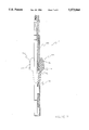
- FIG. 6 is a partial sectional view of the apparatus of the present invention with the slip means being retracted.
- FIG. 7 is a partial sectional view of the apparatus of FIG. 6 with the slip means being expanded.
- FIG. 8 is a schematic of a typical well bore with the invention as seen in FIG. 1 wherein the wire line has parted.
- FIG. 1 a typical well bore 2 with the apparatus 4 of the present application being suspended in the well bore 2 on a wire line is shown.
- the wire line unit 8 is located at the surface.
- the apparatus 4 is part of a bottom hole assembly 9 which also contains pressure means and a setting tool, both of which will be described hereinafter.
- the well bore 2 is generally a casing string that intersects various subterranean reservoirs. Some of the reservoirs will contain commercial deposits of hydrocarbons.
- the well bore 2 will be completed to the reservoir 10 with the reservoir fluids and gas being produced into the lower annulus 12 through the perforations 14.
- the well bore 2 may contain a production tubing string 16 with a production packer 18 being operatively associated therewith so that an upper annulus 20 and lower annulus 12 is formed.
- the production string 16 may contain nipple profiles (not shown) for the setting of the bottom hole assembly.
- the bottom hole assembly 9 will contain setting means for setting the entire assembly 9 into the nipple profile, as is well understood by those of ordinary skill in the art.
- An example of a setting tool is sold under the name "GS" Running Tool, "X” Running Tool, or Hydraulic Soft Set Tool.
- the bottom hole assembly 9 will be connected to the wire line 6 while the opposite end of the apparatus 4 will have attached thereto pressure means 26 for measuring the pressure within the well bore 2.
- the pressure means 26 will be a quartz type known as Amerada Pressure Gauge and available from Geophysical Research Corporation. It should be noted that like numbers appearing in the various figures refer to like components throughout the application.
- the bottom hole assembly also contains weight jars 28 and a set of spang jars 30.
- the mandrel 50 comprises an outer cylindrical surface 52 that contains external thread means 54.
- the outer surface 52 to a second outer surface 56 that in turn extends to a third outer cylindrical surface 58.
- the surfaces 52, 56 and 58 together form a ledge, or fishing neck as commonly referred to those of ordinary skill in the art, which can be used in the retrieval of the bottom hole assembly 9 in the event that the bottom hole assembly becomes separated from the wire line 6.
- the third outer surface 58 leads to a fourth outer surface 60 which concludes at the radial surface 62 that in turn leads to the outer cylindrical surface 64.
- the surface 64 ultimately concludes at the outer surface 66 which contains the external thread means 68.
- the lower mandrel sub 70 also known as the cone.
- the lower mandrel sub comprises a conical surface 72 that leads to an outer cylindrical surface 74, with the outer surface 74 concluding at the radial shoulder 76. Extending radially inward is a bore that will contain internal thread means 78 that will make up to the external threads 68.
- the housing member 82 of the present invention contains an upper section that has a first outer surface 84 that will extend to a second outer surface 86 that will have contained thereon external thread means 88 which in turn leads to the inner bore 90.
- the inner bore 90 will conclude at the radial surface 92.
- the housing member 82 also consist of an intermediate section that has a first outer surface 94 that extends to a section containing a plurality of elongated window sections 96 for placement of the slip means which will be described later in this application.
- the outer surface 94 terminates at shoulder 98.
- Extending radially inward of shoulder 98 is the internal bore 100 that will contain first thread means 102 and second thread means 104.
- the second thread means 104 engages the external thread means 88.
- the first thread means 102 engages the lower section of the housing member 82 to be described hereinafter.
- the intermediate section also contains apertures 105 for placement of a pin for the pivotal placement of the slip means, which will be described later in the application.
- the housing member 82 also consist of a lower section that has a first outer cylindrical surface 106 that has contained thereon external thread means 108 that will engage with the thread means 102.
- the first outer surface 106 extends to the second outer surface 110. Extending radially inward will be the inner bore surface 112 that will have contained thereon the internal threads 114.
- FIG. 4 is an enlarged cross-section of one arm of the slip means 120.
- the slip means contains a first end 122 and a second end 124.
- An outer surface 126 extends from the first end 122 with the outer surface being substantially arcuate in order to match the circumference of the well bore 2.
- the outer surface 126 is chamfered and extends to a plurality of engaging members (also known as a plurality of serrated edges) 128 for engaging the well bore 2 when extended as will be discussed later in the application.
- the engaging members 128 are generally formed of carburize teeth and are of a buttress thread form with a right hand helix.
- the engaging members 128 will in turn extend to the chamfered outer surface 130, with the outer surface terminating at the surface 132. Extending from the surface 132 is another chamfered surface 134 that in turn extends to the radially flat second end surface 124.
- On the internal portion of the slip means 120 will be the first internal surface 136 that in turn stretches to a second internal surface 138 with the second internal surface extending to a chamfered internal surface 140 and thereafter advancing to the rounded end 142 and then concluding at the first end 122.
- an aperture 144 that will receive a pin for pivotally attaching the slip means 120 to the housing 82 and in particular the aperture 105.
- the illustration depicts a cross-section of the apparatus taken along line A--A of FIG. 6.
- This view shows the arcuate surface of the slip means 120, and in particular the engaging members 128, so that the wall of the tubing string 16 may be engaged.
- the slip means 120 are retracted within the housing member 82. In this position, the biasing means 152 acts to oppose the second ends 124 of both slip means 120.
- the apparatus 4 is part of a bottom hole assembly 9 that is positioned within the well bore 2 on the wire line 6.
- the weight of the bottom hole assembly 9 causes the housing member 82 to be pulled downward.
- the urging means 150 for urging the mandrel 50 downward relative to the housing member 82 is compressed.
- the urging means 150 is a conical spring. Therefore, the cone section 70, and in particular the surfaces 140 of the slip means 120 and the surface 72 of the cone, cooperate with one another so that the slip means 120 are allowed to retract as seen in FIG. 6. In this position, the slip means 120 are recessed within the window section 96 of the housing member 82.
- a biasing means 152 for biasing the two slip means 120, and in particular the second end 124 of the arms 120, in a position opposite one another as seen in FIGS. 5 & 6.
- the biasing means 152 which in the preferred embodiment is a conical spring, acts to separate the ends 124 of each arm 120 so that the ends 122 are thrust together.
- FIG. 7 depicts the case wherein there is no longer any effective gravitational weight acting on the housing. Such a case is where the wire line 6 becomes parted or alternatively the bottom hole assembly is blown out the well bore 2. As shown, the slip means 120 have been expanded.
- the reasons for the parting of the wire line differ but some examples may be due to encountering a sharp object in the well bore or alternatively due to a restriction in the well that causes the operator to pull excessively on the wire line thereby causing the wire to break.
- the reasons for being blown out of the hole may include swabbing of the well fluids and gas when taking a flowing bottom hole pressure survey.
- the apparatus 4 will catch the walls of the production tubing 16 any time effective weight from beneath the apparatus 4 is lost.
- the spring 150 acts against the radial surface 65 and forces the cone 70 downward relative to the housing member 82.
- the conical surface 72 acts against the chamfered internal surface 140 of the dual slips 120 so that the dual slips 120 are forced outward into engagement with the production tubing 16.
- the biasing means 152 is compressed.
- FIG. 8 depicts the slip means 120 expanded due to a parted wire line.
- the slip means 120 will thereafter stop movement.
- the assembly may be retrieved by lowering a retrieving tool into the well bore 2.
- control of the flow can be reestablished i.e. the well is shut-in.
- the weight of the bottom hole assembly as well as the pull from the surface by the operator will cause the slips 120 to retract (due to the weight of the bottom hole assembly.
- the bottom hole assembly will include a spring loaded collar stop, an Amerada Pressure gauge, the automatic catch apparatus of the invention disclosed herein, rope socket and a hydraulic running/pulling tool.
- the method includes setting the collar stop by conventional means within a tubing collar. Next, the operator allows the tool string weight to be set down which has the effect of allowing the slip means to expand against the walls of the tubing.
- the conventional hydraulic pulling/running tool will release the bottom hole assembly, and the operator can pull out of the well bore.
- the pressure gauges have been set down hole without any jarring.
- the pressure gauges cannot move down because of the collar stop, and can not go up because of the automatic catch apparatus.
Landscapes
- Life Sciences & Earth Sciences (AREA)
- Engineering & Computer Science (AREA)
- Geology (AREA)
- Mining & Mineral Resources (AREA)
- Physics & Mathematics (AREA)
- Environmental & Geological Engineering (AREA)
- Fluid Mechanics (AREA)
- General Life Sciences & Earth Sciences (AREA)
- Geochemistry & Mineralogy (AREA)
- Measuring Fluid Pressure (AREA)
Abstract
Description
Claims (11)
Priority Applications (1)
| Application Number | Priority Date | Filing Date | Title |
|---|---|---|---|
| US08/448,783 US5573064A (en) | 1995-05-24 | 1995-05-24 | Automatic catch apparatus and method |
Applications Claiming Priority (1)
| Application Number | Priority Date | Filing Date | Title |
|---|---|---|---|
| US08/448,783 US5573064A (en) | 1995-05-24 | 1995-05-24 | Automatic catch apparatus and method |
Publications (1)
| Publication Number | Publication Date |
|---|---|
| US5573064A true US5573064A (en) | 1996-11-12 |
Family
ID=23781671
Family Applications (1)
| Application Number | Title | Priority Date | Filing Date |
|---|---|---|---|
| US08/448,783 Expired - Fee Related US5573064A (en) | 1995-05-24 | 1995-05-24 | Automatic catch apparatus and method |
Country Status (1)
| Country | Link |
|---|---|
| US (1) | US5573064A (en) |
Cited By (6)
| Publication number | Priority date | Publication date | Assignee | Title |
|---|---|---|---|---|
| US5787978A (en) * | 1995-03-31 | 1998-08-04 | Weatherford/Lamb, Inc. | Multi-face whipstock with sacrificial face element |
| US6024168A (en) * | 1996-01-24 | 2000-02-15 | Weatherford/Lamb, Inc. | Wellborne mills & methods |
| US6056056A (en) * | 1995-03-31 | 2000-05-02 | Durst; Douglas G. | Whipstock mill |
| US6155349A (en) | 1996-05-02 | 2000-12-05 | Weatherford/Lamb, Inc. | Flexible wellbore mill |
| US20090084544A1 (en) * | 2007-09-28 | 2009-04-02 | Schlumberger Technology Corporation | Method and system for interpreting swabbing tests using nonlinear regression |
| US20170114604A1 (en) * | 2014-05-23 | 2017-04-27 | Halliburton Energy Services, Inc. | Downhole cable grab assembly and method of use |
Citations (6)
| Publication number | Priority date | Publication date | Assignee | Title |
|---|---|---|---|---|
| US3670821A (en) * | 1970-12-21 | 1972-06-20 | Jack W Tamplen | Locking device and method and apparatus for emplacing same |
| US3677346A (en) * | 1970-12-21 | 1972-07-18 | Jack W Tamplen | Reversible arming method and apparatus for emplacing a locking device in tubing |
| US3797573A (en) * | 1972-09-05 | 1974-03-19 | Baker Oil Tools Inc | Full opening safety valve |
| US4139058A (en) * | 1976-07-26 | 1979-02-13 | Otis Engineering Corporation | Hydraulic stop and orienting tool for well system installation |
| US4658904A (en) * | 1985-05-31 | 1987-04-21 | Schlumberger Technology Corporation | Subsea master valve for use in well testing |
| US5327975A (en) * | 1991-04-08 | 1994-07-12 | Rotating Production Systems, Inc. | Tubing anchor catcher with rotating mandrel |
-
1995
- 1995-05-24 US US08/448,783 patent/US5573064A/en not_active Expired - Fee Related
Patent Citations (7)
| Publication number | Priority date | Publication date | Assignee | Title |
|---|---|---|---|---|
| US3670821A (en) * | 1970-12-21 | 1972-06-20 | Jack W Tamplen | Locking device and method and apparatus for emplacing same |
| US3677346A (en) * | 1970-12-21 | 1972-07-18 | Jack W Tamplen | Reversible arming method and apparatus for emplacing a locking device in tubing |
| US3797573A (en) * | 1972-09-05 | 1974-03-19 | Baker Oil Tools Inc | Full opening safety valve |
| US4139058A (en) * | 1976-07-26 | 1979-02-13 | Otis Engineering Corporation | Hydraulic stop and orienting tool for well system installation |
| US4154298A (en) * | 1976-07-26 | 1979-05-15 | Otis Engineering Corporation | Well tubing hanger |
| US4658904A (en) * | 1985-05-31 | 1987-04-21 | Schlumberger Technology Corporation | Subsea master valve for use in well testing |
| US5327975A (en) * | 1991-04-08 | 1994-07-12 | Rotating Production Systems, Inc. | Tubing anchor catcher with rotating mandrel |
Cited By (8)
| Publication number | Priority date | Publication date | Assignee | Title |
|---|---|---|---|---|
| US5787978A (en) * | 1995-03-31 | 1998-08-04 | Weatherford/Lamb, Inc. | Multi-face whipstock with sacrificial face element |
| US6056056A (en) * | 1995-03-31 | 2000-05-02 | Durst; Douglas G. | Whipstock mill |
| US6024168A (en) * | 1996-01-24 | 2000-02-15 | Weatherford/Lamb, Inc. | Wellborne mills & methods |
| US6155349A (en) | 1996-05-02 | 2000-12-05 | Weatherford/Lamb, Inc. | Flexible wellbore mill |
| US20090084544A1 (en) * | 2007-09-28 | 2009-04-02 | Schlumberger Technology Corporation | Method and system for interpreting swabbing tests using nonlinear regression |
| US8086431B2 (en) * | 2007-09-28 | 2011-12-27 | Schlumberger Technology Corporation | Method and system for interpreting swabbing tests using nonlinear regression |
| US20170114604A1 (en) * | 2014-05-23 | 2017-04-27 | Halliburton Energy Services, Inc. | Downhole cable grab assembly and method of use |
| US10392889B2 (en) * | 2014-05-23 | 2019-08-27 | Halliburton Energy Services, Inc. | Downhole cable grab assembly and method of use |
Similar Documents
| Publication | Publication Date | Title |
|---|---|---|
| US6237687B1 (en) | Method and apparatus for placing a gravel pack in an oil and gas well | |
| US5377749A (en) | Apparatus for setting hydraulic packers and for placing a gravel pack in a downhole oil and gas well | |
| AU2005240983B2 (en) | Latch mechanism guide | |
| US5310001A (en) | Method of retrieving a downhole tool utilizing non-rotational workstrings | |
| US6658981B2 (en) | Thru-tubing stackable perforating gun system and method for use | |
| US6196309B1 (en) | Down hole pulling tool and method of use | |
| US4570707A (en) | Releasable latch for downhole well tools | |
| JPH0347473B2 (en) | ||
| US20070046051A1 (en) | Spear head overshot for use in a cable guided fishing assembly | |
| US4949791A (en) | Method and apparatus for securing and releasing continuous tubing in a subterranean well | |
| CA1270191A (en) | Line moving apparatus for wireline supported tools | |
| CA2471394C (en) | Hydraulic overshot tool without a nozzle, and method of retrieving a cylinder | |
| US4122899A (en) | Well perforator with anchor and method | |
| CA2441138C (en) | Removal of tubulars from wells | |
| US3812911A (en) | Retrievable blanking plug | |
| US5573064A (en) | Automatic catch apparatus and method | |
| US6848507B2 (en) | Expandable wirefinder and method for use of same | |
| US11199064B2 (en) | Integrated debris catcher and plug system | |
| US11808094B2 (en) | Flexi-string for washout below a casing shoe | |
| US4582136A (en) | Method and apparatus for placement and retrieval of downhole gauges | |
| US3951211A (en) | Method for selectively retrieving a plurality of well packers | |
| EP1201875A2 (en) | Downhole tool | |
| US11352846B2 (en) | Advanced pulling prong | |
| RU2781432C1 (en) | Hoisting tool and method for extracting a downhole tool | |
| US2881842A (en) | Safety device |
Legal Events
| Date | Code | Title | Description |
|---|---|---|---|
| AS | Assignment |
Owner name: SPECIALTY MACHINE & SUPPLY, INC., LOUISIANA Free format text: ASSIGNMENT OF ASSIGNORS INTEREST;ASSIGNOR:HISAW, JACK C.;REEL/FRAME:007494/0955 Effective date: 19950522 |
|
| AS | Assignment |
Owner name: SIRROM INVESTMENTS INC., TEXAS Free format text: SECURITY INTEREST;ASSIGNOR:SPECIALTY MACHINE & SUPPLY, INC.;REEL/FRAME:009046/0086 Effective date: 19980227 |
|
| AS | Assignment |
Owner name: FLEET CAPITAL CORPORATION, TEXAS Free format text: SECURITY INTEREST;ASSIGNOR:SPECIALTY MACHINE & SUPPLY, INC.;REEL/FRAME:009052/0093 Effective date: 19971219 |
|
| AS | Assignment |
Owner name: SPECIALTY MACHINE & SUPPLY, INC., LOUISIANA Free format text: ASSIGNMENT OF ASSIGNORS INTEREST;ASSIGNOR:SIRROM INVESTMENTS, INC.;REEL/FRAME:010388/0507 Effective date: 19991101 |
|
| AS | Assignment |
Owner name: SPECIALTY MACHINE & SUPPLY, LLC, A CORPORATION OF Free format text: MERGER;ASSIGNOR:SPECIALTY MACHINE & SUPPLY, INC., A CORPORATION OF LOUISIANA;REEL/FRAME:010567/0476 Effective date: 19971219 |
|
| FPAY | Fee payment |
Year of fee payment: 4 |
|
| AS | Assignment |
Owner name: SPECIALITY MACHINE & SUPPLY LLC, LOUISIANA Free format text: RELEASE;ASSIGNOR:FLEET CAPITAL CORPORATION;REEL/FRAME:012199/0519 Effective date: 20010601 |
|
| AS | Assignment |
Owner name: WEATHERFORD/LAMB, INC., TEXAS Free format text: ASSIGNMENT OF ASSIGNORS INTEREST;ASSIGNOR:WEUS HOLDING, INC.;REEL/FRAME:012785/0653 Effective date: 20020318 |
|
| REMI | Maintenance fee reminder mailed | ||
| LAPS | Lapse for failure to pay maintenance fees | ||
| STCH | Information on status: patent discontinuation |
Free format text: PATENT EXPIRED DUE TO NONPAYMENT OF MAINTENANCE FEES UNDER 37 CFR 1.362 |
|
| FP | Lapsed due to failure to pay maintenance fee |
Effective date: 20041112 |