US5568569A - Method and apparatus for analyzing digital video images by merging displacement vectors - Google Patents
Method and apparatus for analyzing digital video images by merging displacement vectors Download PDFInfo
- Publication number
- US5568569A US5568569A US08/258,613 US25861394A US5568569A US 5568569 A US5568569 A US 5568569A US 25861394 A US25861394 A US 25861394A US 5568569 A US5568569 A US 5568569A
- Authority
- US
- United States
- Prior art keywords
- pixel block
- blocks
- digital video
- target
- pixels
- Prior art date
- Legal status (The legal status is an assumption and is not a legal conclusion. Google has not performed a legal analysis and makes no representation as to the accuracy of the status listed.)
- Expired - Lifetime
Links
Images


Classifications
-
- H—ELECTRICITY
- H04—ELECTRIC COMMUNICATION TECHNIQUE
- H04N—PICTORIAL COMMUNICATION, e.g. TELEVISION
- H04N19/00—Methods or arrangements for coding, decoding, compressing or decompressing digital video signals
- H04N19/90—Methods or arrangements for coding, decoding, compressing or decompressing digital video signals using coding techniques not provided for in groups H04N19/10-H04N19/85, e.g. fractals
- H04N19/96—Tree coding, e.g. quad-tree coding
-
- G—PHYSICS
- G06—COMPUTING OR CALCULATING; COUNTING
- G06T—IMAGE DATA PROCESSING OR GENERATION, IN GENERAL
- G06T7/00—Image analysis
- G06T7/20—Analysis of motion
- G06T7/223—Analysis of motion using block-matching
- G06T7/231—Analysis of motion using block-matching using full search
-
- H—ELECTRICITY
- H04—ELECTRIC COMMUNICATION TECHNIQUE
- H04N—PICTORIAL COMMUNICATION, e.g. TELEVISION
- H04N19/00—Methods or arrangements for coding, decoding, compressing or decompressing digital video signals
- H04N19/50—Methods or arrangements for coding, decoding, compressing or decompressing digital video signals using predictive coding
- H04N19/503—Methods or arrangements for coding, decoding, compressing or decompressing digital video signals using predictive coding involving temporal prediction
- H04N19/51—Motion estimation or motion compensation
-
- G—PHYSICS
- G06—COMPUTING OR CALCULATING; COUNTING
- G06T—IMAGE DATA PROCESSING OR GENERATION, IN GENERAL
- G06T2207/00—Indexing scheme for image analysis or image enhancement
- G06T2207/10—Image acquisition modality
- G06T2207/10016—Video; Image sequence
Definitions
- This invention relates to video signal processing generally and particularly to systems for providing a compressed digital video signal representative of a full color video signal.
- a target image in a sequence of images is divided into a plurality of blocks of pixels, such blocks may typically be 8 ⁇ 8 pixels in dimension.
- a target region comprising at least one pixel block is selected from the target image.
- the image preceding the target image is analyzed in order to locate a region of the preceding image which closely matches the target region of the target image.
- Block matching techniques based on mean-square-error or mean-absolute-error are typically used to locate the region of the preceding image which closely matches the target region of the target image. If no motion has occurred, the preceding and target regions will have the same coordinates within the image frame.
- the preceding region will be offset or translated relative to the target region by an amount which is represented by a displacement vector.
- This process is typically repeated for each target region in the target image, thereby yielding a displacement vector for each target region.
- These displacement vectors are thereafter applied to a previous reconstructed image to form a predicted image.
- An error image is formed from the difference between the target image and the predicted image.
- the displacement vectors and the error image are then encoded for subsequent use by a decoder in decoding the compressed digital video signal.
- a known motion compensation system is described in U.S. Pat. No. 5,134,478 to Golin, entitled “Method And Apparatus For Compressing And Decompressing A Digital Video Signal Using Predicted And Error Images", the contents of which is hereby incorporated herein by reference.
- each target image may typically be broken up into approximately 1K blocks (8 ⁇ 8), it can take a substantial number of bits to separately encode a displacement vector for each block. It was found that if some or all of the displacement vectors could be made the same (or merged) without unduly increasing the bits needed to encode the error image, the result would be more efficient encoding.
- a method and apparatus for analyzing a sequence of one or more digital motion video images Displacement vectors are assigned to a plurality of blocks in an image.
- First and second block groups are selected from the plurality of blocks, the first and second block groups being adjacent and having corresponding first and second displacement vectors assigned thereto.
- a first error measure associated with predicting the second block group using the second displacement vector is determined.
- a second error measure associated with predicting the second block group using said first displacement vector is determined.
- An error change is obtained from the first and second error measures.
- a variance value is determined from the magnitudes of the pixels in the second block group, and a merge-factor is obtained from the error change, the variance, and the number of pixels in the second block group.
- the second block group is reassigned to the first displacement vector if the merge-factor is less than a merge-threshold.
- a method and apparatus for analyzing a sequence of one or more digital motion video images Displacement vectors are assigned to a plurality of parent blocks in an image. Each parent block is divided into a plurality of target blocks. A target block is selected from the plurality of target blocks, and a plurality of parent blocks are associated with the selected target block. A plurality of error measures are calculated for the selected target block by successively applying the displacement vector assigned to each associated parent block to the selected target block. The displacement vector associated with the minimum error measure is selected from the plurality of error measures. The selected displacement vector is assigned to the selected target block if the minimum error measure is below a threshold.
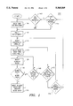
- FIG. 1 is a flow diagram illustrating a system for merging displacement vectors in one dimension according to a preferred embodiment of the present invention.
- FIG. 2 is a flow diagram illustrating a system for merging displacement vectors in two dimensions according to a preferred embodiment of the present invention.
- FIG. 2A is a diagram illustrating a pixel block that is 4-connected to several of its neighbors.
- FIG. 3 is a diagram illustrating four parent pixel blocks that have been quartered into sixteen target pixel blocks.
- FIG. 4 is a flow diagram illustrating a system for assigning displacement vectors to target pixel blocks according to a preferred embodiment of the present invention.
- a target image is divided into blocks 16 ⁇ 16 pixels in dimension, although pixel blocks of other dimensions may be used.
- Displacement vectors are assigned to each pixel block in the target image using known motion analysis methods.
- a one-dimensional merging analysis (shown in FIG. 1) is next applied to each column of blocks and then to each row of blocks in the target image.
- a two-dimensional merging analysis (shown in FIG. 2) is applied to each group of blocks in the target image.
- displacement vectors are assigned to each 8 ⁇ 8 pixel block by applying a quartering analysis (shown in FIG. 4) to each 16 ⁇ 16 block in the target image.
- the one-dimensional merging analysis, the two-dimensional merging analysis and the quartering analysis are performed together in sequence, each of these methods may used independently or in combination with only one of the other methods to merge displacement vectors within a target image.
- group of blocks or “block groups” refer to a set of one or more "adjacent" blocks having the same displacement vector. Where a one-dimensional merging analysis is being applied to a column of blocks, adjacent blocks must be vertically adjacent; where a one-dimensional merging analysis is being applied to a row of blocks, adjacent blocks must be horizontally adjacent. Where a two-dimensional merging analysis is being performed, adjacent blocks must be 4-connected as described in FIG. 2A.
- the one-dimensional merging analysis is preferably applied on a column-by-column basis to each column of pixel blocks in the target image, and then on a row-by-row basis to each row of pixel blocks in the target image.
- this result is achieved by first transposing the array of blocks and operating on the transposed array on a row-by-row basis in accordance with system 100, and then transposing these processed rows and repeating the process.
- one-dimensional merging can be applied iteratively. For example, merge all rows and then all columns, and then repeat the process one or more times until there are no further changes in displacement vector assignments.
- the thresholding value used for merging (Mergethresh) can be gradually reduced after each iteration.
- row selection means 105 is provided for selecting a row of pixel blocks from the target image for processing.
- Displacement ordering means 110 identifies the displacement vector assigned to each block in the target image, and orders the displacement vectors in accordance with their frequency of occurrence.
- Displacement ordering means 110 preferably orders the displacement vectors in descending order of occurrence so that the one having the highest frequency of occurrence is first and the one having the lowest frequency of occurrence is last.
- means 110 would order the displacements as follows: B, A, C.
- Displacement vector selector means 115 is provided for selecting a displacement vector (Trial -- D) from the ordered list of displacement vectors assembled by means 110.
- Means 115 preferably selects first the displacement vector in the selected row having the highest frequency of occurrence in the target image. In the preferred embodiment, after all block groups in the selected row associated with this selected displacement vector are processed, means 115 selects the displacement vector in the selected row having the second highest frequency of occurrence in the target image and all block groups associated with this displacement vector are processed. The process is then repeated in descending order of occurrence for all remaining displacement vectors that appear on the order list assembled by means 110, until all block groups in the selected row associated with the displacement vector having the lowest frequency of occurrence are processed.
- Block group selector means 120 is provided for selecting a first block group having an associated displacement vector equal to Trial -- D
- block group selector means 125 is provided for selecting a second block group positioned adjacent to the first block group.
- Merge testing means 130 is provided for determining whether to "merge" the second block group into the first block group. If means 130 determines that the second block group should be merged into the first block group, merging means 135 assigns the displacement vector Trial -- D to the second block group.
- Means 140 is provided for repeating the process from means 125 for each block group that is adjacent to the first block group, which grows after the merge, means 145 is provided for repeating the process from means 120 for each block group having an associated displacement vector equal to Trial -- D, and means 150 is provided for repeating the process from means 115 for each displacement vector (in descending order of occurrence) on the ordered list that appears in the selected row.
- merge testing means 130 determines a first error measure associated with predicting the second block group using its originally assigned displacement vector, and a second error measure associated with predicting the second block group using Trial -- D as its displacement vector.
- mean-square-error calculations are used to determine the first and second error measures.
- calculations based on mean-absolute-error or correlation values may be used to determine the first and second error measures.
- Merge testing means 130 also determines an error change from the first and second error measures.
- the error change represents the difference between the mean-square-error that would result from predicting the second block group using its originally assigned displacement vector (the first error measure) and the mean-square error that would result from predicting the second block group using Trial -- D as its displacement vector (the second error measure).
- the error change will be negative where predicting the second block group with displacement vector Trial -- D results in a reduced mean-square-error value.
- merge testing means 130 calculates the statistical variance of the magnitudes of the pixels in the second block group.
- merge testing means 130 calculates a MergeFactor in accordance with equation (1) below:
- Numpels represents the number of pixels (in the second block group) involved in the merge
- Deltamse is the signed increase in the mean-square-error that results from predicting the second block group with a displacement vector of Trial -- D
- var is the statistical variance of the pixels in the second adjacent block group
- mise is the mean-square-error that results from predicting the second block group using its originally assigned displacement vector
- q is the current quantization being used
- k0 and k1 are constants with typical values of 0.25 and 0.1, respectively.
- merge testing means 130 determines whether a merge should take place by comparing the MergeFactor to a MergeThresh.
- MergeThresh is preferably a constant with a typical value of 3.0.
- Merging means 135 merges the second block group into the first block group if MergeFactor is less than MergeThresh.
- means 155 determines whether any change in displacement vector assignments occurred during the most recent one-dimensional merging process by comparing the current displacement vector assignments for each block in the row with the displacement vector assignments that existed before the most recent one-dimensional merging process was applied to the row. Alternatively, means 155 can determine whether any change in displacement vector assignments occurred by testing to see whether a logical variable is set to a TRUE condition. In this embodiment, the logical variable is initialized to FALSE by means 110 and set to TRUE by means 135 if a merge does take place. If any change in the displacement vector assignments has occurred as a result of the most recent one-dimensional merging process, the process is repeated from means 110. This repetition continues until application of the merging process from means 110 results in no further changes to the displacement vector assignments. Finally, means 160 is provided for repeating the above one-dimensional merging process for each row in the target image.
- FIG. 2 shows a flow diagram illustrating a system 200 for merging displacement vectors in two dimensions according to a preferred embodiment of the present invention.
- displacement ordering means 205 identifies a displacement vector for each block in the target image, and orders the displacement vectors in accordance with their frequency of occurrence.
- Displacement ordering means 205 operates substantially in accordance with means 110.
- group of blocks or “block groups” are used herein to refer to a set of one or more "adjacent" blocks having the same displacement vector.
- blocks are considered adjacent if they are 4-connected.
- Blocks are 4-connected if they share a common horizontal or vertical boundary line.
- blocks 291, 293, 295 and 297 are each 4-connected to block 290, while blocks 292, 294, 296 and 298 are not 4-connected to block 290.
- Displacement vector selector means 210 is provided for selecting a displacement vector (Trial -- D) from the ordered list of displacement vectors assembled by means 205.
- Means 210 preferably selects first the displacement vector having the highest frequency of occurrence. In the preferred embodiment, after all block groups associated with this selected displacement vector are processed, means 210 selects the displacement vector having the second highest frequency of occurrence and all block groups associated with this displacement vector are processed. The process is then repeated in descending order of occurrence for all remaining displacement vectors on the order list assembled by means 205, until all block groups associated with the displacement vector having the lowest frequency of occurrence are processed.
- Block group selector means 215 is provided for selecting a first block group having an associated displacement vector equal to Trial -- D
- block group selector means 220 is provided for selecting a second block group position adjacent to the first block group.
- Merge testing means 225 is providing for determining whether to "merge" the second block group into the first block group.
- Merge testing means 225 functions substantially in accordance with merge testing means 130, with two exceptions. First, in merge testing means 225, the first and second block groups being tested do not necessarily lie in the same row or column of the target image. Second, in contrast to means 130, merge testing means 225 calculates MergeThresh in accordance with equation (2) below:
- number -- adj is the number of blocks having a displacement vector equal to Trial -- D that share a common horizontal or vertical boundary with the second block group
- k2 is a constant with a typical value of 3.0.
- merging means 230 assigns the displacement vector Trial -- D to the second block group.
- Means 235 is provided for repeating the process from means 220 for each block group that is adjacent to the first block group, means 240 is provided for repeating the process from means 215 for each block group having an associated displacement vector equal to Trial -- D, and means 245 is provided for repeating the process from means 210 for each displacement vector (in descending order of occurrence) on the order list of displacement vectors assembled by means 205.
- means 250 determines whether any change in displacement vector assignments occurred during the most recent two-dimensional merging process by comparing the current displacement vector assignments for each block in the target image with the displacement vector assignments that existed before the most recent two-dimensional merging process was applied to the target image. Alternatively, means 250 can determine whether any change in displacement vector assignments occurred by testing to see whether a logical variable is set to a TRUE condition. In this embodiment, the logical variable is initialized to FALSE by means 205 and set to TRUE by means 230 if a merge does take place. If any change in the displacement vector assignments has occurred as a result of the two-dimensional merging process, the process is repeated from means 205. This repetition continues until application of the two-dimensional merging process from means 205 results in no further changes to the displacement vector assignments.
- a one-dimensional merging analysis first is applied to the columns and rows of 16 ⁇ 16 pixel blocks in the target image. Next, the two-dimensional merging analysis described above is applied to these blocks. Finally, a quartering analysis is applied to each pixel block in the target image. During the quartering process, each 16 ⁇ 16 pixel block (or parent pixel block) is divided into a plurality of target pixel blocks. In the preferred embodiment shown in FIG. 3, each parent block 310, 320, 330, 340 is divided into four target blocks which are each 8 ⁇ 8 pixels in dimension.
- parent pixel block 310 is divided into target blocks 312, 314, 316, 318; parent pixel block 320 is divided into target blocks 322, 324, 326, 328; parent pixel block 330 is divided into target blocks 332, 334, 336, 338; and parent pixel block 340 is divided into target blocks 342, 344, 346, 348. If the target block size were 16 ⁇ 16 (as opposed to 8 ⁇ 8), the quartering analysis described in this section would preferably begin with parent blocks that were 32 ⁇ 32 pixels in dimension.
- displacement vector assignment means 405 is provided for assigning a displacement vector to each parent block in the target image.
- means 405 begins by assigning initial displacement vectors to each parent block using known motion analysis methods. Thereafter, the initial displacement vector assignments are modified using first the one-dimensional merging analysis and thereafter the two-dimensional merging analysis described above.
- Block division means 410 is provided for dividing each parent block into a plurality of target blocks as shown in FIG. 3.
- Target block selector means 415 selects a target block for processing.
- each target block in the target image is associated with four parent blocks. These four associated parent blocks include the one parent block that the selected target block lies within and the three other parent blocks that border the selected target block.
- target block 318 will be associated with parent block 310 (in which target block 318 lies) and with parent blocks 320, 330 and 340 (which border target block 318).
- Error measurement means 420 is provided for determining a plurality of error measures for the selected target block by successively applying the displacement vector assigned to each associated parent block to the selected target block.
- means 420 will calculate first, second, third and fourth error measures in accordance with the errors that would result from predicting target block 318 with the displacement vectors assigned to parent blocks 310, 320, 330 and 340, respectively.
- Means 420 preferably calculates these error measures based on the mean-square-error that would result from predicting the selected target block with the displacement vectors described above. In alternative embodiments, means 420 may use calculations based on mean-absolute-error or correlation values to determine these error measures.
- Displacement vector selector means 425 is provided for selecting, based on the plurality of error measures determined by means 420, that displacement vector which, when used to predict the selected target block, results in the minimum error measure. Thus, continuing with the example of target block 318, means 425 will identify the minimum of the four error measures determined by means 420, and it will then select the displacement vector associated with that minimum error measure.
- Means 430 is provided for calculating a test error measure for the selected target block based on the minimum error measure identified by means 425.
- the test error measure is determined in accordance with equation (3) below:
- minimum mse is the minimum error measure (based on a mean-square-error determination) identified by means 425
- var is the statistical variance of the magnitudes of the pixels in the selected target block
- q is the current quantization
- k3 is a parameter having a typical value of 0.25.
- Test error thresholding means 435 is provided for comparing the test error measure to a threshold value.
- the threshold value is set to 2.0. If the test error measure is less than the threshold, then means 440 assigns the displacement vector selected by means 425 to the selected target block; otherwise, means 445 assigns a displacement vector to the selected target block using an alternative method such as the block matching technique described in U.S. Pat. No. 5,134,478 to Golin, entitled “Method And Apparatus For Compressing And Decompressing A Digital Video Signal Using Predicted And Error Images", the contents of which is hereby incorporated herein by reference.
- Means 450 is provided for determining whether each target block in the target image has been processed. If each target block has not been processed, means 450 directs that the process be repeated from means 415 until each target block in the target image has been processed. Once this processing is complete, means 455 encodes the displacement vectors assigned to each of the target blocks in the target image.
- the present invention may be implemented using an Intel model i860 parallel processor or a general purpose processor.
- the present invention may be embodied in other specific forms without departing from the spirit or essential attributes of the invention. Accordingly, reference should be made to the appended claims, rather than the foregoing specification, as indicating the scope of the invention.
Landscapes
- Engineering & Computer Science (AREA)
- Multimedia (AREA)
- Signal Processing (AREA)
- Computer Vision & Pattern Recognition (AREA)
- Physics & Mathematics (AREA)
- General Physics & Mathematics (AREA)
- Theoretical Computer Science (AREA)
- Compression Or Coding Systems Of Tv Signals (AREA)
Abstract
Description
MergeFactor=(Numpels*Deltamse)/(var+k0*q.sup.2 +k1*mse) (1)
MergeThresh=k2*num.sub.-- adj (2)
Test.sub.-- Error=minimum mse/(var+k3*q.sup.2) (3)
Claims (24)
Priority Applications (1)
| Application Number | Priority Date | Filing Date | Title |
|---|---|---|---|
| US08/258,613 US5568569A (en) | 1992-12-31 | 1994-06-10 | Method and apparatus for analyzing digital video images by merging displacement vectors |
Applications Claiming Priority (2)
| Application Number | Priority Date | Filing Date | Title |
|---|---|---|---|
| US99914892A | 1992-12-31 | 1992-12-31 | |
| US08/258,613 US5568569A (en) | 1992-12-31 | 1994-06-10 | Method and apparatus for analyzing digital video images by merging displacement vectors |
Related Parent Applications (1)
| Application Number | Title | Priority Date | Filing Date |
|---|---|---|---|
| US99914892A Continuation | 1992-12-31 | 1992-12-31 |
Publications (1)
| Publication Number | Publication Date |
|---|---|
| US5568569A true US5568569A (en) | 1996-10-22 |
Family
ID=25545959
Family Applications (1)
| Application Number | Title | Priority Date | Filing Date |
|---|---|---|---|
| US08/258,613 Expired - Lifetime US5568569A (en) | 1992-12-31 | 1994-06-10 | Method and apparatus for analyzing digital video images by merging displacement vectors |
Country Status (1)
| Country | Link |
|---|---|
| US (1) | US5568569A (en) |
Cited By (5)
| Publication number | Priority date | Publication date | Assignee | Title |
|---|---|---|---|---|
| US5721595A (en) * | 1996-06-19 | 1998-02-24 | United Microelectronics Corporation | Motion estimation block matching process and apparatus for video image processing |
| US5960119A (en) * | 1995-01-09 | 1999-09-28 | International Business Machines Corporation | Method of and system for encoding digital images |
| US20070047806A1 (en) * | 2005-08-31 | 2007-03-01 | Pingshan Li | Scatterness of pixel distribution |
| US20070098277A1 (en) * | 2004-03-09 | 2007-05-03 | Takashi Watanabe | Transmitting apparatus, image processing system, image processing method, program, and recording medium |
| US20080247657A1 (en) * | 2000-01-21 | 2008-10-09 | Nokia Corporation | Method for Encoding Images, and an Image Coder |
Citations (2)
| Publication number | Priority date | Publication date | Assignee | Title |
|---|---|---|---|---|
| US5028996A (en) * | 1989-06-26 | 1991-07-02 | Matsushita Electric Industrial Co., Ltd. | Picture coding method |
| US5151784A (en) * | 1991-04-30 | 1992-09-29 | At&T Bell Laboratories | Multiple frame motion estimation |
-
1994
- 1994-06-10 US US08/258,613 patent/US5568569A/en not_active Expired - Lifetime
Patent Citations (2)
| Publication number | Priority date | Publication date | Assignee | Title |
|---|---|---|---|---|
| US5028996A (en) * | 1989-06-26 | 1991-07-02 | Matsushita Electric Industrial Co., Ltd. | Picture coding method |
| US5151784A (en) * | 1991-04-30 | 1992-09-29 | At&T Bell Laboratories | Multiple frame motion estimation |
Cited By (7)
| Publication number | Priority date | Publication date | Assignee | Title |
|---|---|---|---|---|
| US5960119A (en) * | 1995-01-09 | 1999-09-28 | International Business Machines Corporation | Method of and system for encoding digital images |
| US5721595A (en) * | 1996-06-19 | 1998-02-24 | United Microelectronics Corporation | Motion estimation block matching process and apparatus for video image processing |
| US20080247657A1 (en) * | 2000-01-21 | 2008-10-09 | Nokia Corporation | Method for Encoding Images, and an Image Coder |
| US7567719B2 (en) * | 2000-01-21 | 2009-07-28 | Nokia Corporation | Method for encoding images, and an image coder |
| US20070098277A1 (en) * | 2004-03-09 | 2007-05-03 | Takashi Watanabe | Transmitting apparatus, image processing system, image processing method, program, and recording medium |
| US20070047806A1 (en) * | 2005-08-31 | 2007-03-01 | Pingshan Li | Scatterness of pixel distribution |
| US7609891B2 (en) * | 2005-08-31 | 2009-10-27 | Sony Corporation | Evaluation of element distribution within a collection of images based on pixel scatterness |
Similar Documents
| Publication | Publication Date | Title |
|---|---|---|
| US5136374A (en) | Geometric vector quantization | |
| US5134478A (en) | Method and apparatus for compressing and decompressing a digital video signal using predicted and error images | |
| US4796087A (en) | Process for coding by transformation for the transmission of picture signals | |
| US5371544A (en) | Geometric vector quantization | |
| US7197074B2 (en) | Phase plane correlation motion vector determination method | |
| US6380986B1 (en) | Motion vector search method and apparatus | |
| US5790269A (en) | Method and apparatus for compressing and decompressing a video image | |
| US8144777B2 (en) | Motion vector detection method and apparatus | |
| EP0609022A2 (en) | Image encoding apparatus | |
| EP0851389B1 (en) | Contour tracing method | |
| US5237397A (en) | Color video data processing | |
| US6078689A (en) | Image information encoding device | |
| US5544239A (en) | Method and apparatus for improving motion analysis of fades | |
| US5347311A (en) | Method and apparatus for unevenly encoding error images | |
| EP0748562A1 (en) | Method and apparatus for data analysis | |
| KR19980702924A (en) | Method and apparatus for determining coordinates of motion determination values for multiple frames | |
| US4811112A (en) | Vector DPCM image coding method and apparatus | |
| US6845130B1 (en) | Motion estimation and compensation for video compression | |
| US5568569A (en) | Method and apparatus for analyzing digital video images by merging displacement vectors | |
| US5721595A (en) | Motion estimation block matching process and apparatus for video image processing | |
| US5838833A (en) | Fractal image compression method and device and fractal image restoration method and device | |
| US20010022852A1 (en) | Method of monitoring the quality of distributed digital images by detecting false contours | |
| KR101217627B1 (en) | Method and apparatus for estimating motion vector based on block | |
| US7107251B1 (en) | Method of evaluating the quality of audio-visual sequences | |
| US6542547B1 (en) | Efficient heuristic based motion estimation method for video compression |
Legal Events
| Date | Code | Title | Description |
|---|---|---|---|
| CC | Certificate of correction | ||
| FEPP | Fee payment procedure |
Free format text: PETITION RELATED TO MAINTENANCE FEES FILED (ORIGINAL EVENT CODE: PMFP); ENTITY STATUS OF PATENT OWNER: LARGE ENTITY |
|
| REFU | Refund |
Free format text: REFUND - PAYMENT OF MAINTENANCE FEE, 4TH YEAR, LARGE ENTITY (ORIGINAL EVENT CODE: R183); ENTITY STATUS OF PATENT OWNER: LARGE ENTITY |
|
| FEPP | Fee payment procedure |
Free format text: PETITION RELATED TO MAINTENANCE FEES GRANTED (ORIGINAL EVENT CODE: PMFG); ENTITY STATUS OF PATENT OWNER: LARGE ENTITY |
|
| FPAY | Fee payment |
Year of fee payment: 4 |
|
| SULP | Surcharge for late payment | ||
| STCF | Information on status: patent grant |
Free format text: PATENTED CASE |
|
| PRDP | Patent reinstated due to the acceptance of a late maintenance fee |
Effective date: 20010907 |
|
| FEPP | Fee payment procedure |
Free format text: PAYER NUMBER DE-ASSIGNED (ORIGINAL EVENT CODE: RMPN); ENTITY STATUS OF PATENT OWNER: LARGE ENTITY Free format text: PAYOR NUMBER ASSIGNED (ORIGINAL EVENT CODE: ASPN); ENTITY STATUS OF PATENT OWNER: LARGE ENTITY |
|
| FPAY | Fee payment |
Year of fee payment: 8 |
|
| FEPP | Fee payment procedure |
Free format text: PAYER NUMBER DE-ASSIGNED (ORIGINAL EVENT CODE: RMPN); ENTITY STATUS OF PATENT OWNER: LARGE ENTITY Free format text: PAYOR NUMBER ASSIGNED (ORIGINAL EVENT CODE: ASPN); ENTITY STATUS OF PATENT OWNER: LARGE ENTITY |
|
| FPAY | Fee payment |
Year of fee payment: 12 |